Hi guys,
I posted recently wanting to rework a Stromberg Carlson amp into a bass amp. However, I quickly realized I was biting off way more than I could chew and have rethought my strategy and have decided on building a bass preamp instead, start small and work my way up!
I have some questions I need answered, attached is a schematic for the build.
1. I think I found a good transformer for the project, it is marketed for standalone reverb units. It has 250vac/25ma and 6.3vac/1A heater. I think that that gives me about 250*1.4 = 350v dc after rectifier, which I probably want to step down to around 300v for the 12ax7s. How do I figure out the size of the resistor I should use to drop the voltage before I build the thing or is that more something you meter as you go and find values that way?
1b. Kind of same as first question, with biasing (cathode biasing in particular) is that something that you do after everything is up and running and you can measure the grid/cathode or is there a way to know that value beforehand? It's frustrating that Ohm's law is so simple mathematically and yet I still don't really understand when to use it.
2. Some things I read say that I should have a center tap on the heater winding to be grounded, but that I could create a false center tap by wiring both legs with identical resistors to ground. Is this legit and again how would I determine the value of the resistor?
3. What size filter caps do you recommend for a project like this? I have a 47uf and a 22uf in the schematic, but this is just from borrowing from other peoples designs and I don't have a firm grasp as to why those values or why use 1 vs. 2 vs. 3 filter caps.
4. Please if you would, look over the schematic attached and ridicule me for any omissions or errors. It is still a work in progress. Also, please let me know and recommendations you have for improving the circuit to work better with bass guitar.
Thanks everyone!
Attachments
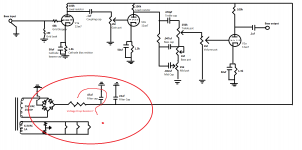
1/ The resistor you are looking as is to stop surges mainly aimed at protecting the diodes. Any amount of resistance in the HT line, when the valves are cold, will make little difference. If you are that worried, use a potential divider as regulation is not an issue.
Use a 4k7 as the surge limiter and place a 10k between the two filter capacitors then place a 120k 3W across the second filter capacitor.
2/ the common value used is 120R but anything will do. This stops the heaters from floating to an unwanted voltage.
3/ 1k3 is not a standard value. Most manufacturers using a 100k anode load choose a 2k2 or 1k8 cathode resistor. That brings the anode voltage down to around 80 - 120volts depending on the gain and characteristics of the chosen valve.
I recommend not using JJ's as they are of low quality compared to Sovtek or other non Chinese manufacturers. The 100n coupling capacitors are rather high in value. For bass 47n is enough without causing flutter. the second stage of a 12AX7 has slightly higher gain than the first. If you are using active pickups, don't forget to place a coupling capacitor in series with the first grid. They tend to leak DC voltage and that will give you strange results. Looks like it is from a classic Fender design.
1/ The resistor you are looking as is to stop surges mainly aimed at protecting the diodes. Any amount of resistance in the HT line, when the valves are cold, will make little difference. If you are that worried, use a potential divider as regulation is not an issue.
Use a 4k7 as the surge limiter and place a 10k between the two filter capacitors then place a 120k 3W across the second filter capacitor.
2/ the common value used is 120R but anything will do. This stops the heaters from floating to an unwanted voltage.
3/ 1k3 is not a standard value. Most manufacturers using a 100k anode load choose a 2k2 or 1k8 cathode resistor. That brings the anode voltage down to around 80 - 120volts depending on the gain and characteristics of the chosen valve.
I recommend not using JJ's as they are of low quality compared to Sovtek or other non Chinese manufacturers. The 100n coupling capacitors are rather high in value. For bass 47n is enough without causing flutter. the second stage of a 12AX7 has slightly higher gain than the first. If you are using active pickups, don't forget to place a coupling capacitor in series with the first grid. They tend to leak DC voltage and that will give you strange results. Looks like it is from a classic Fender design.
Should I not be worried? I was thinking that 350v would be pushing it for the 12ax7 plates. Or I guess that's what you mean about placing the 120k across the 2nd filter cap, is there a way to know exactly how much voltage that will drop? Sorry does across mean parallel with the filter cap and going to ground?

One of my basses does have active pickups, what size cap would you suggest between the input and grid?
I wont be using crap tubes, I have some Mesa Boogie branded 12ax7s from an old project that I will use as I've always had great experiences with their gear.
Thanks for the comments, I appreciate it.
Verbstank:
You are on the right track.
A few comments :
- JJ ECC83S will fit perfectly here , don't use substandard brands
- The grid resistor 1M on the first stage , in general i would use somewhat smaller,
250k or so.
- the other stages, don't rely that a potentimeter will be all you need as grid resistor,
connect a 1Meg ( or 500k ) after the viper , this will save the day if the pot fails.
For power supply design, there is a software tool to help with it, made by fellow diyaudio user, duncanamps. PSUD2 this great piece of software is free for hobbyists and really worth trying.
Ok I will try that out when I get home, thanks.
Another question I should have considered a long time ago, is there a big difference between designing a tube pre for use with a solid state power section vs a tube power section? I would like this pre to be able to do both. The only things I can think of are the voltage output of the preamp and the impedance of the ss power amp input. Are these things to stress about or are they usually not a problem? Having 3 gain stages per channel I'd like to think that I could supply ample voltage to any amp, but unsure about the effect of impedance of pre and power, any comments appreciated, will start another Google rampage on this topic when I get home.
Most "classical" tube power amps has a fairly high input impedance, in orderOk I will try that out when I get home, thanks.
Another question I should have considered a long time ago, is there a big difference between designing a tube pre for use with a solid state power section vs a tube power section? I would like this pre to be able to do both. The only things I can think of are the voltage output of the preamp and the impedance of the ss power amp input. Are these things to stress about or are they usually not a problem? Having 3 gain stages per channel I'd like to think that I could supply ample voltage to any amp, but unsure about the effect of impedance of pre and power, any comments appreciated, will start another Google rampage on this topic when I get home.
of > 250kohm. Many transistor amps has around 10kohm, this is a nostopper
for your above preamp. The usual cure is to add a cathode follower.
A single ECC82 and some components will do for both channels.
Most "classical" tube power amps has a fairly high input impedance, in order
of > 250kohm. Many transistor amps has around 10kohm, this is a nostopper
for your above preamp. The usual cure is to add a cathode follower.
A single ECC82 and some components will do for both channels.
Petertub:
Ok so I read through the Valve Wizard's pages on DC-coupled and AC-coupled cathode followers. I amended my schematic and have reattached it, can you tell me if I'm on the right track with this? I still don't really understand how it drops the impedance, but that will come with more reading I guess. Right now I'm just treating it as a reversed normal triode stage, instead of taking the output from the anode and applying the load resistor to the anode, I am taking output from cathode and applying load resistor to cathode. Is this in a nutshell the idea here? I also replaced the last ECC83/12ax7 with an ECC82/12au7 for use as the cathode follower and will use one triode of it for each channel.
Does this now mean that I cannot run this preamp with a tube power amp? Sorry for all the questions!
Attachments
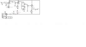
That circuit won't work, the bass LP filtering should be before the last tube.
The output is then at the top of the 100k, which goes directly to ground.
With a 10k input ss amp, the bass will be reduced in range compared to a tube amp.
Why have the tone controls for the bass output?
The output is then at the top of the 100k, which goes directly to ground.
With a 10k input ss amp, the bass will be reduced in range compared to a tube amp.
Why have the tone controls for the bass output?
Last edited:
That circuit won't work, the bass LP filtering should be before the last tube.
The output is then at the top of the 100k, which goes directly to ground.
With a 10k input ss amp, the bass will be reduced in range compared to a tube amp.
Why have the tone controls for the bass output?
So change the .1uf cap to before the 12au7 tube rather than right before the output? Or are you saying change the placement of the tone circuit, possibly put it instead between the two 12ax7 stages? Or am I wildly off-course?
So change the .1uf cap to before the 12au7 tube rather than right before the output? Or are you saying change the placement of the tone circuit, possibly put it instead between the two 12ax7 stages? Or am I wildly off-course?
Remove the 1.3k and 50uF. Connect the bottom of the 100k to ground.
Connect the 0.1uF to the top of the 100k.
You also will need a coupling capacitor between the volume control and grid.
Also a resistor biasing network for the grid to get it at a DC potential that is
a little less than you want for the output cathode. Otherwise the tube will be cut off.
Why do you want a tone circuit for the bass output?
Last edited:
Remove the 1.3k and 50uF. Connect the bottom of the 100k to ground.
Connect the 0.1uF to the top of the 100k.
You also will need a coupling capacitor between the volume control and grid.
Also a resistor biasing network for the grid to get it at a DC potential that is
a little less than you want for the output cathode. Otherwise the tube will be cut off.
Why do you want a tone circuit for the bass output?
Ok I understand most of this. Updated schematic attached. I guess I need to read up on biasing a cathode follower, because as you are saying I will eliminate the cathode bias (which makes sense in my brain since I'm taking the output from the cathode now) and now be biasing the grid instead.
But I'm lost on your question of why I want a tone circuit? I want a tone circuit for use as a tone circuit... so I can attenuate frequencies with pots... I must be missing something here, sorry I am new to all of this.
Attachments
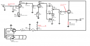
Now at the grid you need a resistor to the power supply, and another resistor to ground.
The values will be determined by the current you want in the tube, but the top resistor could be 1M to start.
Perhaps around 1M for the other resistor also, bu this will vary with your current. What is the power supply voltage?
The values will be determined by the current you want in the tube, but the top resistor could be 1M to start.
Perhaps around 1M for the other resistor also, bu this will vary with your current. What is the power supply voltage?
Last edited:
Now at the grid you need a resistor to the power supply, and another resistor to ground.
The values will be determined by the current you want in the tube, but the top resistor could be 1M to start.
Perhaps around 1M for the other resistor also, bu this will vary with your current. What is the power supply voltage?
Attached is addition with resistors.
Power supply voltage is 250vac, again I'm new to all of this, but I've read that that will rectify to 1.4*250=350vdc, then I had some questions about stepping that down but figured if I can get it to 300vdc that should be good for all tubes involved?
I think I only want ~3 or 4ma current to the grid? Just like the other 12ax7 tubes? Or does a cathode follower require a different current?
Thanks for your time rayma
Attachments

Instead, you may want to keep the 12AX7, and "follow" it by the 12AU7 cathode follower.
This will give more gain and reduce the other parts needed. The 12AU7 grid can then be directly
connected to the 12AX7 plate.
So are you saying swap back to a 12ax7 where I have the 12au7 now, then add another stage that will be the 12au7 cathode follower directly after the 12ax7 stage? I am limited by the current on the heater wind to use only 3 tubes, and I would like to make this a dual channel pre, so 6 triodes total and 3 for each channel. If that falls through oh well, I can devote all 3 tubes to just one channel, but that would be a last resort.
I keep running into the same problem, my lack of understanding in the power section. How do I go about finding the load resistor for the cathode follower? I chose 100k for the 12ax7 loads and the 10k resistor between the filter caps all from suggestions, and as much as I read trying to understand why these values I still don't have a firm grasp on it.
Last edited:
Hmmm so are you saying swap back to a 12ax7 where I have the 12au7 now, and add another stage that will be the 12au7 cathode follower directly after the 12ax7 stage that gains the tone control? I am limited by the current on the heater wind to use only 3 tubes, and I would like to make this a dual channel pre, so 6 triodes total and 3 for each channel.
Ok, just remember with the cathode follower there is no gain (output voltage about same as input).
Then try the last circuit with the resistors biasing the 12AU7 grid.
The 10k in the power supply will drop some voltage, depending on how much current the tubes take.
The voltage drop would be 10k x total plate current in all tubes added together (in amps).
Given your power supply voltage, then all the resistor values have to be determined by designing.
It's likely the 12AU7 cathode resistor will be less than 100k. That would be more for a 12AX7 follower.
Last edited:
Ok, just remember with the cathode follower there is no gain (output voltage about same as input).
Then try the last circuit with the resistors biasing the 12AU7 grid.
The 10k in the power supply will drop some voltage, depending on how much current the tubes take.
The voltage drop would be 10k x total plate current in all tubes added together (in amps).
Given your power supply voltage, then all the resistor values have to be determined by designing.
It's likely the 12AU7 cathode resistor will be less than 100k. That would be more for a 12AX7 follower.
Thanks so much for all the responses and time. So thinking that if they were 3 12ax7 tubes, taking maybe 4ma of current per plate, I would say that the 10k resistor drops the voltage by 10,000 * 0.012 = 120volts? The 12au7 looks like it takes much more current, near 20ma, so then if 2 12ax7 and 1 12au7, 10000*.028=280v? seems like such a high number? But I guess that means I change the resistor value to something lower?
Am I doing this reasoning correctly?
edit: I didn't realize the cathode follower provided no gain, thanks for that
2nd edit: Doh I used max plate current for those numbers vs. normal operation current it seems, but that would still be the same thinking behind it?
Last edited:
Thanks so much for all the responses and time. So thinking that if they were 3 12ax7 tubes, taking maybe 4ma of current per plate, I would say that the 10k resistor drops the voltage by 10,000 * 0.012 = 120volts? The 12au7 looks like it takes much more current, near 20ma, so then if 2 12ax7 and 1 12au7, 10000*.028=280v? seems like such a high number? But I guess that means I change the resistor value to something lower?
Usually a 12AX7 will be configured have about 1mA plate current.
The 12AU7 is often used with 5mA-10mA
Here's a more advanced follower circuit, similar to what you need. They also mention the resistor grid bias circuit,
but this one is probably better for your purposes. It takes about 8mA plate current.
So roughly 20mA total current, 10k x 20mA = 200V drop, so reduce the 10k power supply resistor
down to 2.5k, to have a drop of 2.5k x 20mA = 50V, about right.
The Valve Wizard -Cathode Follower
.
Attachments
Last edited:
- Status
- This old topic is closed. If you want to reopen this topic, contact a moderator using the "Report Post" button.
- Home
- Live Sound
- Instruments and Amps
- Designing my first tube preamp