Usually a 12AX7 will be configured have about 1mA plate current.
The 12AU7 is often used with 5mA-10mA
Here's a more advanced follower circuit, similar to what you need. They also mention the resistor grid bias circuit.
The Valve Wizard -Cathode Follower
.
Yeah I edited my last post to say I was dumb and used the max current ratings rather than operating condition currents.
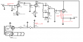
Attached an updated schematic if you are still hanging in there
") Values are substitutes until I work out the math on what they should be.
Values are substitutes until I work out the math on what they should be.I had read through that Valve Wizard page previously but it makes much more sense now that you have explained a few things! So his section on Choosing the Load is exactly what I would use to find the value for the load resistor?
And because the cathode follower provides no gain, is that why you were questioning the tone circuit? Because I would not be gaining it back up before the output? If that is the case, would it be better to put the tone circuit in between the two 12ax7s and allow the 2nd 12ax7 stage to go directly to the cathode follower?
Attachments
Yeah I edited my last post to say I was dumb and used the max current ratings rather than operating condition currents.
Attached an updated schematic if you are still hanging in there
I had read through that Valve Wizard page previously but it makes much more sense now that you have explained a few things! So his section on Choosing the Load is exactly what I would use to find the value for the load resistor?
And because the cathode follower provides no gain, is that why you were questioning the tone circuit? Because I would not be gaining it back up before the output? If that is the case, would it be better to put the tone circuit in between the two 12ax7s and allow the 2nd 12ax7 stage to go directly to the cathode follower?
Right, their circuit is about the same as yours, so just use their resistors.
Moving the tone won't change the total gain, but will raise the noise level.
This circuit should be pretty quiet if there's enough gain.
If you think the gain is enough as-is, go ahead with this circuit.
You may have to readjust the power supply resistor to get close to 300VDC,
but 2.5k should be a good start.
Last edited:
Right, their circuit is about the same as yours, so just use their resistors.
Moving the tone won't change the total gain, but will raise the noise level.
If you think the gain is enough as-is, go ahead with this circuit. Should be good.
You may have to readjust the power supply resistor to get close to 300VDC,
but 2.5k should be a good start.
Man thank you so much, I feel like this was a breakthrough for understanding how to value all my resistors! So after all of this, what have I done? Dropped the output impedance (how much would I expect)? Does this affect the preamp's ability to work with tube power sections?
I think I will nix the idea of a 2 channel pre and just make it all 1 channel. If so then I could set another 12ax7 to gain post tone controls, and then feed that plate directly into that CFollower1 pdf?
The 12AU7 follower output impedance will be very roughly 350R, which should drive an amp ok.
You can add the 12AX7 circuit, between the volume control, and the capacitor to the grid of the 12AU7.
Then with only one channel, you would increase the power supply resistor up to around 4.7k,
but adjust the value to get 300V. Use at least a 2W resistor there.
Last edited:
The 12AU7 follower output impedance will be very roughly 350R, which should drive an amp ok.
You can add the 12AX7 circuit, between the volume control, and the capacitor to the grid of the 12AU7.
Then with only one channel, you would increase the power supply resistor up to around 4.7k,
but adjust the value to get 300V. Use at least a 1W resistor there.
Assume I end up using all 6 triodes on either one channel or two, why would the resistor value change? Wouldn't I be using the same total plate current either way?
Assume I end up using all 6 triodes on either one channel or two, why would the resistor value change?
Wouldn't I be using the same total plate current either way?
Right now one channel has three 12AX7 halves and one 12AU7 half.
That's roughly 11mA, so 50V/.011 = 4.5k to drop 50V.
If you have two channels, current is twice as much, so halve the 4.7k to 2.4k.
If you only make one channel, you can use one entire tube for the first two stages, then a 12AX7 half for the third,
and half of the 12AU7 for the fourth. The unused sections of the last two stages wouldn't use current, since
you just ground the P/K/G terminals of the unused tube sections.
If you do make two channels, the tubes can be in a line with ch A wiring on one side, and ch B on the other side.
Use half of each tube for each channel and the wiring will work out well that way.
Last edited:
...I was thinking that 350v would be pushing it for the 12ax7 plates....
The raw 350V will be full of ripple. You want to take 10%-30% drop in several R-C filters to clean it up. In the area of 280V. 12AX7 can take straight 300V all day long.
The tube does not take the *whole* supply voltage. It has to work in a "fair fight" with a plate resistor. To over-simplify, half voltage on resistor, half voltage on tube.
Because the 12AX7 is a high impedance we often have to let it take more voltage. In your 1.3k+100k bias, maybe 65%, so 180V. In the VERY popular Fender 1.5k+100k bias, about 70%, so 200V. Fender actually ran preamp +B over 350V on some models (cuz he had 450V available on the big bottles).
...12ax7 tubes, taking maybe 4ma of current per plate...
The only way to approach 4mA on 12AX7 is to jam it hard-ON. But for audio we have to bias it half-on, so we can swing both ways like the strings.
Anyway we can get a close estimate of current since we know the resistor and the approximate voltage. Say 280V of B+ and 180V on tube. So it must be 100V across the resistor. Which is 100k. What is the current?
The raw 350V will be full of ripple. You want to take 10%-30% drop in several R-C filters to clean it up. In the area of 280V. 12AX7 can take straight 300V all day long.
The tube does not take the *whole* supply voltage. It has to work in a "fair fight" with a plate resistor. To over-simplify, half voltage on resistor, half voltage on tube.
Because the 12AX7 is a high impedance we often have to let it take more voltage. In your 1.3k+100k bias, maybe 65%, so 180V. In the VERY popular Fender 1.5k+100k bias, about 70%, so 200V. Fender actually ran preamp +B over 350V on some models (cuz he had 450V available on the big bottles).
The only way to approach 4mA on 12AX7 is to jam it hard-ON. But for audio we have to bias it half-on, so we can swing both ways like the strings.
Anyway we can get a close estimate of current since we know the resistor and the approximate voltage. Say 280V of B+ and 180V on tube. So it must be 100V across the resistor. Which is 100k. What is the current?
1mA? 1.8mA? 2.8mA?
I don't yet grasp how Ohm's law works... Is V in the equation the amount lost across the resistor? the initial B+ amount? The 180v seen by the tube? If I take it to mean the voltage lost across the resistor that doesn't make sense because that means current is related to voltage change not voltage present...? So then I would say we are measuring the current seen by the tube at 180v? Sorry for being so beginner about this, reading the definition just doesn't seem to clear it all up for me, it's just simple algebra yet still unclear to me.
Is that then the purpose of the bias, to again adjust the voltage after the RC filtering to a better range for the tube? Again something that I've read a lot about but not 100% sure on the actual concept, I had thought of it more as a way to equalize between the anode and cathode so that there would be no signal flow if there was no input/grid change.
>> 100V across the resistor. Which is 100k. What is the current?
> 1mA? 1.8mA? 2.8mA?
100 Volts across 100k.
100k is 100,000 Ohms. (Sometimes the mix-up is not the math but the units.)
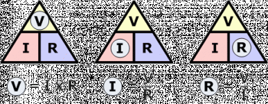
I = V/R
100V/100,000 is 0.001 Amps.
0.001 Amps is 1 mA.
Since we have a lot of k-resistors, and often work in the mA range, it is useful to note that the k and m cancel out:
100V/100k = 1mA
> 1mA? 1.8mA? 2.8mA?
100 Volts across 100k.
100k is 100,000 Ohms. (Sometimes the mix-up is not the math but the units.)
I = V/R
An externally hosted image should be here but it was not working when we last tested it.
100V/100,000 is 0.001 Amps.
0.001 Amps is 1 mA.
Since we have a lot of k-resistors, and often work in the mA range, it is useful to note that the k and m cancel out:
100V/100k = 1mA
Attachments
Last edited:
>> 100V across the resistor. Which is 100k. What is the current?
> 1mA? 1.8mA? 2.8mA?
100 Volts across 100k.
100k is 100,000 Ohms. (Sometimes the mix-up is not the math but the units.)
I = V/R
An externally hosted image should be here but it was not working when we last tested it.
100V/100,000 is 0.001 Amps.
0.001 Amps is 1 mA.
Since we have a lot of k-resistors, and often work in the mA range, it is useful to note that the k and m cancel out:
100V/100k = 1mA
So what happens when you want to measure current at a given point? Or is that just not how that works? To measure the current at the plate, why are we measuring the current across the resistor? Because that will inherently be what we see at the plate?
Does this make sense? Sorry to turn it into an electricity lesson
As for the cathode follower,Yeah I edited my last post to say I was dumb and used the max current ratings rather than operating condition currents.
Attached an updated schematic if you are still hanging in there
I had read through that Valve Wizard page previously but it makes much more sense now that you have explained a few things! So his section on Choosing the Load is exactly what I would use to find the value for the load resistor?
And because the cathode follower provides no gain, is that why you were questioning the tone circuit? Because I would not be gaining it back up before the output? If that is the case, would it be better to put the tone circuit in between the two 12ax7s and allow the 2nd 12ax7 stage to go directly to the cathode follower?
make the cathode follower like the example in walve wizard :
The Valve Wizard -Cathode Follower
470 ohm cathode <> grid, 18k to ground. ECC82 will do just fine!
As for the cathode follower,
make the cathode follower like the example in walve wizard :
The Valve Wizard -Cathode Follower
470 ohm cathode <> grid, 18k to ground. ECC82 will do just fine!
Hey Petertub,
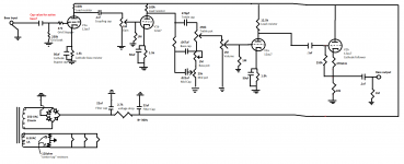
Thanks for the confirmation on that. Attached is what I HOPE is a final schematic for this thing. If you could look it over that would be awesome, I think my cathode follower is set correctly, I am just wondering now about the load resistor and bias resistor for the other half of the ECC82 (which I'm going to use to gain back up after the tone stack).
Originally I had this project as 3 tubes powering 2 channels, but now I've just simplified it to one channel, two tubes (12ax7 and 12au7). For the 12au7, is it the same procedure to find the load resistor (ask how much current I want to see at the plate (~8mA), how much voltage I want to see (~200 volts) and so I must drop 100 volts from the B+ of 300, therefore 100v/8mA=12.5k load resistor?) How about the cathode bias resistor for the 12au7 gain stage?
Attachments
Verbstank
You could decrease the input cap to the cathode follower, it's very high impedance. The output cap could be increased for drive capability. Load resistor, i still claim 18k is best.
I would however decrease the outermost 1Meg resistor to 100k, this to discharge the
output cap fast at power on / off
The grid resistor 250k is ok, the loading on previous stage is even lower then it seems
as the grid resistor is bootstraped from the cathode.
Finally, a "lead-out" resistor of 100 ohm between the cathode and the output cap is
recommended to avoid instability.
If possible. the ecc82 filaments should be elevated to some 25Volts below cathode ( i would advice the cathode to be at 100Volt ) 200 volts between cathode and filament is way
too much.
This later requrement suggests that a second 6.3V ( or 12V ) winding is needed
to allow the other tubes have their filament around 0V
Last edited:
Verbstank
You could decrease the input cap to the cathode follower, it's very high impedance. The output cap could be increased for drive capability. Load resistor, i still claim 18k is best.
I would however decrease the outermost 1Meg resistor to 100k, this to discharge the
output cap fast at power on / off
The grid resistor 250k is ok, the loading on previous stage is even lower then it seems
as the grid resistor is bootstraped from the cathode.
Finally, a "lead-out" resistor of 100 ohm between the cathode and the output cap is
recommended to avoid instability.
If possible. the ecc82 filaments should be elevated to some 25Volts below cathode ( i would advice the cathode to be at 100Volt ) 200 volts between cathode and filament is way
too much.
This later requrement suggests that a second 6.3V ( or 12V ) winding is needed
to allow the other tubes have their filament around 0V
Ammended for those values and attached.
Well so do people not normally run 12ax7s and 12au7s heater on the same winding?
Or is it that the B+ needs to change before it is sent to the 12au7 i.e. do I just put another filter cap + resistor in between the power supply and 12au7 plates and run the tube at a lower voltage? Does this make sense?
I guess I could look for a new transformer but this was a pretty good option given I didn't find many with low HT current for preamp and high 6.3v current for multiple tubes.
Attachments
..why are we measuring the current across the resistor?...
"Across" is wrong tinking. "Through".
So what happens when you want to measure current at a given point?...
You have to *break* the circuit and insert a current meter.
This is normally difficult. If there is a resistor in the circuit, you can measure the voltage across the resistor and compute the current.
Yes, I think you should step away from the electronics books and get a basic electricity book.
The reason i recommended a separate filament circuit for the 12au7 is that the cathode will
have > 100 Volt . There is a limit how many volts are allowed between filament and cathode
(the insulation is minute and has limits). Thus the 12au7 filament should have a DC offset
to minimize the voltage between cathode and filament. This offset might be obtained be a
large resistor from the cathode to the filament in question.
If you don't have another winding, one option would be to replace the 12au7 with a FET
 Moved to Instruments & Amps since this is a bass pre-amp.
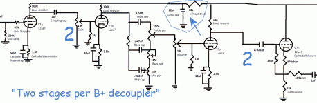
Running all the stages from the same rail could be an issue - normally you'd string RC decoupling along the chain both to prevent oscillatary feedback paths through the supply rail, and to allow the input tubes to run at lower voltage. The latter reason isn't relevant here I think, but letting the output tube pump current directly into the same supply node as feeds the input tube is worrying - depends how much gain you have.
Running all the stages from the same rail could be an issue - normally you'd string RC decoupling along the chain both to prevent oscillatary feedback paths through the supply rail, and to allow the input tubes to run at lower voltage. The latter reason isn't relevant here I think, but letting the output tube pump current directly into the same supply node as feeds the input tube is worrying - depends how much gain you have.
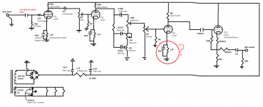
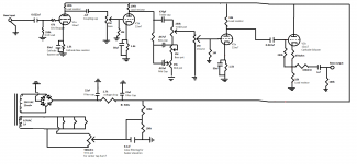
Attached is schematic how it stands now,
So if I understand correctly, running the input 12ax7 stage on the same supply as the 12au7 cathode follower is the problem (is the CF being called the "output tube"?) because as the CF operates it will send unwanted feedback back into the supply line and therefore end up in the 12ax7 input stage as well? And having another filter cap + resistor between the CF supply and the rest of the supply is what you're recommending?
Sorry, I am still very new to all this.
Attachments
- Status
- This old topic is closed. If you want to reopen this topic, contact a moderator using the "Report Post" button.
- Home
- Live Sound
- Instruments and Amps
- Designing my first tube preamp