A problem I can't figure out with a pair of EL84 in a fixed bias P-P amp. Class AB.
It is a guitar amp, but the problem is in the output stage, and could apply to any tube amp.
The initial state of the amp was:
One EL84 tube blown, along with its burnt-out screen grid resistor- resistor and both tubes replaced.
One Control grid to PI coupling caps was dodgy - now both are new and check OK.
Quick post repair test: Loud 60Hz hum.
More tests where everything seems OK
OT winding DC resistances all seems correct.
PT winding DC resistances all seems correct. All voltages tally with the schematic.
Filter caps all check OK.
Resistance measurements on both tube sockets without the Power tubes inserted:
Both tube sockets measure identically in all tests:
Continuity and resistance to ground from control grid, cathode, and the filaments all correct in respect to the ratings of the resistors in their circuit paths.
Plate to control grid - gives a sweeping reading from 220K to around 1M
Filament to plate – around 4.5M
Voltage measurements without the power tubes inserted:
Both tube sockets measure identically in all tests:
Filament voltage normal
Bias voltages correct.
Plate and screen voltages are as expected – correct, and (practically) free from AC.
Now here is where it gets strange:
Voltage measurements with one power tubes inserted in the previously unaffected socket
V5- Tubes Plate: 336VDC & 75AC
V4- Empty sockets plate supply: 336VDC & 350VAC
Plug both tubes in:
V5- Tubes Plate: 336VDC & 3.3VAC
V4- Tubes Plate: 336VDC & 538VAC … and the tube is noticeably hotter.
When applying the multimeter probes to the plates for measuring, the loud humming that is present gets noticeably louder when measuring V4, but disappears when measuring V5.
Any suggestions or thoughts would be welcome.
Is the tube oscillating ? Install grid and screen stoppers!A problem I can't figure out with a pair of EL84 in a fixed bias P-P amp. Class AB.
It is a guitar amp, but the problem is in the output stage, and could apply to any tube amp.
The initial state of the amp was:
One EL84 tube blown, along with its burnt-out screen grid resistor- resistor and both tubes replaced.
One Control grid to PI coupling caps was dodgy - now both are new and check OK.
Quick post repair test: Loud 60Hz hum.
More tests where everything seems OK
OT winding DC resistances all seems correct.
PT winding DC resistances all seems correct. All voltages tally with the schematic.
Filter caps all check OK.
Resistance measurements on both tube sockets without the Power tubes inserted:
Both tube sockets measure identically in all tests:
Continuity and resistance to ground from control grid, cathode, and the filaments all correct in respect to the ratings of the resistors in their circuit paths.
Plate to control grid - gives a sweeping reading from 220K to around 1M
Filament to plate – around 4.5M
Voltage measurements without the power tubes inserted:
Both tube sockets measure identically in all tests:
Filament voltage normal
Bias voltages correct.
Plate and screen voltages are as expected – correct, and (practically) free from AC.
Now here is where it gets strange:
Voltage measurements with one power tubes inserted in the previously unaffected socket
V5- Tubes Plate: 336VDC & 75AC
V4- Empty sockets plate supply: 336VDC & 350VAC
Plug both tubes in:
V5- Tubes Plate: 336VDC & 3.3VAC
V4- Tubes Plate: 336VDC & 538VAC … and the tube is noticeably hotter.
When applying the multimeter probes to the plates for measuring, the loud humming that is present gets noticeably louder when measuring V4, but disappears when measuring V5.
Any suggestions or thoughts would be welcome.
Get a matched pair !
Randomly selected tubes may differ wild
Last edited:
Your thoughts are the same as my first ideas....Is the tube oscillating ? Install grid and screen stoppers!
Get a matched pair !
Randomly selected tubes may differ wild
Control grid resistors of 1K5 are present and correct.
Screen grid resistors of 100 Ohm are installed, but this is maybe a bit small to block all oscillation senarios....I will try adding 500 Ohm onto the tube socket.
Tubes are new, and are a standard matched pair.
Last edited:
Not all tubes sold as "matched" are anywhere close to matched.Your thoughts are the same as my first ideas....
Control grid resistors of 1K5 are present and correct.
Screen grid resistors of 100 Ohm are installed, but this is maybe a bit small to block all oscillation senarios....I will try adding 500 Ohm onto the tube socket.
Tubes are new, and are a standard matched pair.
Try another pair from another vendor, someone like mcshane that does real matching.
As may be...but the described problem would not be induced by a pair of tubes not quite up to cork sniffer standards....vin ordinaire is palatable enough to do the job.Not all tubes sold as "matched" are anywhere close to matched.
Try another pair from another vendor, someone like mcshane that does real matching.
Some of the best sounding guitar amps I have built, sound at their best with totally mismatched output tubes.....but the above described problem has never resulted from that scenario.
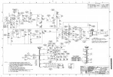
Do you have a schematic even if its hand drawn - its difficult to help without one.
When you say V4- Tubes Plate: 336VDC & 538VAC what did you measure the VAC with - its huge. If its a multimeter they tend to roll of at high frequencies. Do you think its 120Hz or much higher. The EL84 should not oscillate with the resistor values you have.
When you say V4- Tubes Plate: 336VDC & 538VAC what did you measure the VAC with - its huge. If its a multimeter they tend to roll of at high frequencies. Do you think its 120Hz or much higher. The EL84 should not oscillate with the resistor values you have.
Cathodes at ground potential.What are the cathode DC volts when at idle?
Do you have a schematic even if its hand drawn - its difficult to help without one.

A Fluke multimeter. Works fine...but just to be sure, other multimeters were also used....same results.When you say V4- Tubes Plate: 336VDC & 538VAC what did you measure the VAC with - its huge. If its a multimeter they tend to roll of at high frequencies. Do you think its 120Hz or much higher. The EL84 should not oscillate with the resistor values you have.
Yes, the AC voltage is huge.
The hum sounds like mains AC 60Hz...or maybe 120Hz.
No..it shouldn't be doing any of the wierd things that it is.....I admit to being stummed on this one...what am I missing?
Last edited:
Been done, and yes, it measures up as ripple free as one would want to expect from the simple RC filter in the amp.Pull the power tubes and check each s0cket pin. Is there CLEAN B+ at both plate and screen pins? Is there CLEAN bias voltage at the grids?
As "Clean" as tens of thousands of similar amps that don't exibit the problem described.
Last edited:
Okay.. i'll see what I can do...I don't quiet understand the reason, but when I open this page I see the schematic I posted big and clear..?OK...
Things like endless speculation can be eliminated by posting a useable schematic of this unit.
The link previously provided does not work.
And so many of us just hate to dig blindly.
I've always had troubles posting images here - in other forums one can usually just drag and drop an image, copy and insert, or at least upload from your computer. Here it seems on can only link to an image uploadingn site, and even then it is dificult to get the link working...I have given up trying a few times before, and this is one of the reasons im not around here so often to post.
Last edited:
This is the full schem, not as neat as the cutout i was trying to post.
An externally hosted image should be here but it was not working when we last tested it.
Last edited:
OK your statements are not really consistent with any fault. So start again, measure the DC voltages on the power supply to check they are all OK (without OP valves). I would then suggest removing the driver valve v38 and seeing if the output stage is the problem. If you measure DC voltage across screen grid resistors it should indicate if the plate current is very roughly OK. Its just possible there's a fault in the power supply low voltage rails which put massive amounts of hum on the PA input. I still don't understand by probing the V5 plate stops the hum unless there is poor connection or HF oscillation.
Well its clearly oscillating at high power levels, probably ultrasonically and maybe pulling down the supply rail - did you measure the supply rail?
First thing is check the supply decoupling caps aren't dried out. Then check if it behaves with the driver tube removed - if so then the whole amp is likely oscillating from unwanted positive feedback somehow.
And take care with those voltages of course...
First thing is check the supply decoupling caps aren't dried out. Then check if it behaves with the driver tube removed - if so then the whole amp is likely oscillating from unwanted positive feedback somehow.
And take care with those voltages of course...
Oscillating it could well be although the fluke I did not think could measure high frequencies.
I can think of one other thing. Its modern solid state bridge rectifier on the HT. If the EL84 went dead short (which it will have done) and the amp stayed in that condition for a while then it may be enough to cook one half of the primary winding in the output transformer. This could produce a shorted turn causing all sorts of HF strange behaviour. It would explain why all the DC voltages checkout and why there is such a difference in plate AC levels when being a transformer you would expect them to be similar at least up to 100KHz.
Looking at the mains fuse and power supply I reckon a shorted EL84 could put >500ma down one side of the transformer primary without blowing the fuse. That's enough to damage it.
You could check DCR on each transformer primary, but you may have to measure inductance. You could put the transformer across a signal gen I guess.
Last edited:
- Status
- This old topic is closed. If you want to reopen this topic, contact a moderator using the "Report Post" button.
- Home
- Live Sound
- Instruments and Amps
- Loud hum, and high AC at idle on one output tube.