Well thanks to USPS not being able to keep there schedule, maybe I will get to play with that mod board today......seriously hate when things are sent via USPS.
But I did download the data sheet on the Quad Op-Amp it uses (attached).
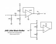
I found a couple of other "buffers" that some others have used in the EB VP Jr too, also attached.
One thing I do see that they all use is the voltage divider DC offset they add into the circuit, totally understand the concept, but hate that way of doing it.
Much cleaner way is to use a Rail Splitter like the TLE2426.
Small add on circuit....
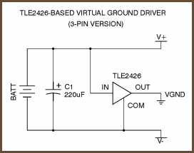
Less possible noise that way too.
I do intend to publish my circuit when done and a PCB file so others can build their own too.
But I did download the data sheet on the Quad Op-Amp it uses (attached).
I found a couple of other "buffers" that some others have used in the EB VP Jr too, also attached.
One thing I do see that they all use is the voltage divider DC offset they add into the circuit, totally understand the concept, but hate that way of doing it.
Much cleaner way is to use a Rail Splitter like the TLE2426.
Small add on circuit....
Less possible noise that way too.
I do intend to publish my circuit when done and a PCB file so others can build their own too.
Attachments

Last edited:
looks like the Data sheet for the TL084 is too big......heres a link instead.
http://www.ti.com/product/TL084
http://www.ti.com/product/TL084
The old +9V standard for stomp-boxes made sense when it was introduced, but only because you could go to the store and easily buy 9V flat batteries.
But even in the 1960s, it wasn't enough voltage. There was very little headroom available. Not a problem when the only pedals on the market were fuzz-boxes, but as soon as pedals with "clean" tone arrived (for example, tremolo, chorus, reverb, etc), 9V became rather painfully inadequate.
In recent years fewer and fewer guitarists actually use 9V batteries to power their pedals. Now that switching power supplies are cheap and reliable and supply clean DC, most guitarists have moved over to a pedal power supply. So the only good reason to use 9V has now almost ceased to exist.
Honestly, I'm really surprised that the isn't a +15 V/0 V/-15 V three-rail power supply standard for guitar pedals. Op-amps have been routine in these little boxes for decades now, and it's just silly that we're still running them on a single-supply, +9V rail.
Some months ago I started hunting around for a suitable 3-prong power connector to use along with a three-rail power supply, and to my utter surprise, found that there isn't any kind of an industry standard connector for this purpose. How is this possible, more than five decades after audio op-amps started to be widely used?
-Gnobuddy
Many months ago, I ran into the same problem (very few options, all of them obscure and expensive). Things like XLR, mini XLR, aircraft connectors, old DIN connectors, etc.Any other options? Maybe a 3.5mm stereo jack. What else?
So I started a thread on the topic, thinking some of our members with lots of manufacturing experience would soon chime in and point me at the "right" connector choice.
To my surprise, that didn't happen - the experienced people did chime in, but they didn't know of any obvious connector choices, either, and suggested the same oddball types mentioned above. Apparently there really aren't any good 3-pin, non-shorting, affordable, compact, power connectors, and there certainly isn't an industry standard. That really surprised me!
By the way: using a stereo or mono 3.5 mm plug / jack for power is a very bad idea. The reason is that as you insert these plugs into the jack, the contacts are briefly shorted to each other. Sparks, arcing, burning, and pitting occur quickly, and the connectors are ruined prematurely.
We have some ancient (and expensive) small equipment at work that uses a 3.5 mm mono jack for power. All the jacks and all the plugs show pitting and blackening. One of these days I'll have to sit down and replace the whole lot with 5.5mm "barrel" power connectors.

-Gnobuddy
I do have the isolated output power supply my pedal board uses, it has two 18 Vdc outputs along with the other eight 9 Vdc outputs.......never even crossed my mind to use a 9 volt battery, no room anyway. (well there is room, but why....cant play my electric guitar without an amp, that's plugged into mains....).
On the rail splitter, this does come down to room on the PCB. Board size is 71mm X 37mm (2.798 X 1.459 for the metric defiant). We have three 1/4 inch phono jacks and a power jack taking up a lot of real-estate, not much room to build a power supply and all the other circuitry needed.
So the 3 pin rail splitter and its supporting cap makes sense, I have used this on other designs. It's way better than injecting DC voltage into the signal path, along with all of the noise it has.
If I use 18 Vdc power that's +9 Vdc and -9 Vdc rails, way more than unity gain will ever need.....but think about the "boost" potential. Heck some pedal power bricks have 24 Vdc out. This makes the power input range 9-24 Vdc....
The Griffin Effect board made it to me last night too, not at all impressed....and they are using a TL074 now, not the TL084 in the picture on their site. Yep, voltage divider into the signal path, no DC blocking cap to the guitar input (wonder if the pickups care about the 4.5 volts on them...).
The whole purpose of the mod is to buffer the tuner and output to prevent loading of the pickups, so why did they put solder pads you have to short for either buffered or direct connection to the input jack to the tuner out? And the goofy LED light..again solder pads to choose color...why oh why?
Not a total loss / waste of money, at least I can use it to check my PCB layout against....and my biggest complaint, where are the instructions......
I now have a semi-plan:
Quad op-amp.
Rail Splitter to keep from injecting DC into the signal path.
Higher quality caps if needed in the signal path.
True buffered in with buffered out on both the tuner and line outputs (unity gain).
Volume control on its own op-amp with possibility of boosting the output.
Any other suggestions?
Last edited:
You have to think back to the time when making a clean 9 volts DC from household AC wasn't such an easy task. Before reliable silicon rectifier diodes existed, never mind Zener diodes, silicon power transistors, or three-terminal linear voltage regulator chips....9 volt battery...why...cant play my electric guitar without an amp, that's plugged into mains...
Back then, you want a clean 9V DC, you use a flat battery!Times certainly have changed. Now a 9V battery costs a small fortune, while small, reliable, affordable SMPS are everywhere. Nowadays using a small SMPS is such an obvious choice that even Luddite guitarists are adopting them.
Have you seen this wonderful doodad? Fifteen bucks (even cheaper in the USA), tiny, +/-15V, completely self-contained: https://www.digikey.ca/products/en?keywords=rac10-15dk/277not much room to build a power supply and all the other circuitry needed.
Electrically speaking, I don't see any difference. Either way, you generate a +4.5V DC rail, halfway between 0V and +9V. There's exactly the same amount of DC voltage involved in either case, no?3 pin rail splitter...way better than injecting DC voltage into the signal path...
Put a decently sized electrolytic cap across the lower of the two equal-value series resistors, and you can easily get negligible noise on the +4.5V node. The +9V should be pretty clean to start with, making this even easier....along with all of the noise it has.
Some years ago there was a discussion on diyAudio about how much voltage, exactly, you can expect from a guitar pickup. One member demonstrated, with oscilloscope captures, his ability to get ten-volt peaks straight out of the humbuckers in his guitar.If I use 18 Vdc power that's +9 Vdc and -9 Vdc rails, way more than unity gain will ever need...
I think that was 10 volts peak-to-peak. Still, +/- 9V doesn't seem like all that much headroom now, does it?
I've heard more than a few "clean" guitar pedals that produce brief bursts of harsh clipping distortion when the guitar pick hits the strings. I really hate that sound!
A bit lower noise, I think. Probably not enough to matter.using a TL074 now, not the TL084 in the picture on their site.
I only remember seeing two buffers in your schematic - why a quad op-amp, and not a dual?
No cap? Really? That is an outright design mistake....no DC blocking cap to the guitar input (wonder if the pickups care about the 4.5 volts on them...)
With the guitar volume at full, that puts the DC resistance of the guitar pickup in parallel with the lower of the two resistors in the voltage divider. You won't get 4.5V bias any longer - you may get very much less, depending on the resistor values in the voltage divider, and the guitar pickup DC resistance.
-Gnobuddy
Going to leave this here for future discussion.....CUI PDQE20-Q24-D15-D
https://www.mouser.com/datasheet/2/670/pdqe20-d-1595964.pdf
https://www.mouser.com/datasheet/2/670/pdqe20-d-1595964.pdf
Back to the research I went, all good points Gno.
The reason for the post above was to remind me to look up this....
DPBW03F-15 MEAN WELL USA Inc. | Power Supplies - Board Mount | DigiKey
+/-15 VDC out at 100mA, more than enough for the op-amp and other needs. 9 to 36 Vdc in 152mA max, most any pedal power brick can do this.
Much better than the rail splitter (only reason I knew about that was one project years ago that used it, a RIAA pre-amp that I built. Totally forgot it still had the "floating voltage one virtual ground....old age, lol).
And I think we cover the 10V peak pickup discussion too.....
Some may be thinking this is way overboard, probably is...but I really don't like sound being "coloured" by electronics that are not designed to do so, a volume pedal should just be that...and when this EB VP Jr sucked the tones away because I plugged in my tuner well it was time to fix it.
My other pedal effects can add the clipping or slewing of the sound, not this one.
Why a Quad, section one is the input buffer (to keep the input impedance stable). Section two can be volume and or gain (still haven't decided if a little boost would be nice or not). Sections three and four are the output buffers (tuner / out).
I am looking at this op-amp, the LME49720 ( http://www.ti.com/lit/ds/symlink/lme49720.pdf ). Has a decent slew rate, should be able to handle the capacitive load of our cables (up to 100pf). And is available in through hole, easier to build for everyone!!!.
Even with the DC to DC convertor I think everything can go on one PCB and fit in the original factory location and use the original sheet metal cover (with one extra hole for the power jack, center neg 2.1mm like most pedals).
And on the bought board, yes a manufacturing mistake placed the input cap and another resistor in the wrong places. Seems they are all "hand built" but not tested before being shipped out. It was a cap in a R1 location, then found a resistor in a C1 location....surface mount too. Glad I did not hook this thing up to power or my rig........
That's a nice find! It seems like the perfect solution for building into a stomp-box.
The other +/-15V module I linked to earlier will work straight off 120V AC, or 230V AC, or DC up to some 400-odd volts! As PRR pointed out, it could even be run straight from a tube guitar amp B+ rail, and provide +/- 15V for op-amps (which could be used for reverb, etc.)
I do think that 10 V from the pickup is definitely an outlier, and a far away and lonely one, several standard deviations from the mean. I doubt one guitarist in a thousand will ever produce that big an output.And I think we cover the 10V peak pickup discussion too...
Frankly, I was quite shocked that it was possible at all!
What do you think about using just one output buffer, and two paralelled output jacks (one for the tuner, one for the rest of the signal chain)? That would let you use a TL072 or other dual JFET-input op-amp, rather than needing a quad.Sections three and four are the output buffers (tuner / out).
If you add a separate build-out resistor (say 2.2k) for each output jack, even heavy loading on one of them won't affect the other, because the op-amp will happily drive a 2.2k load without any difficulty. Even if one output jack was accidentally shorted, nothing would change at the other output jack.
-Gnobuddy
> CUI PDQE20-Q24-D15-D
2 Watt max out. For one/few opamps this is gross over-kill. Like buying a 20-passenger bus to haul you and your lover. (Yeah, my neighbor does, but also to take motorcycles to Florida.)
Since we are not talking gallons of gasoline, the idle power "may not matter". However 150mA here 150mA there, collect enough toys and eventually your 1,500mA pedal-wart conks out and dies. Is there a 1W or 0.5W series of the same idea?
Agreed. (Actually it's 3W, a bit worse than you were pointing out.)2 Watt max out. For one/few opamps this is gross over-kill.
But: no-load current is only 16 mA at 24V DC input. (The datasheet doesn't say if or how that changes at 9 V DC input.)
This isn't wonderfully low, but maybe not terrible either - 16 mA is equivalent to worse-case current draw from a single NE5532 with no load on its output (TI datasheet.)
Even 16 mA is a bit much for use with 9 V flat batteries, but should be no problem with a 9 V power brick. For a number of years I've used a little One Spot 9V brick, bought for maybe $15 USD. Even that little PSU is rated for around 2 amps max output.
I would say the size is very nice, the price is very nice, and the idle current consumption is acceptable in some use cases. I wonder what the RFI issues might be like, though, if this is mounted in the same housing as the FX pedal?
-Gnobuddy
Attachments
> Actually it's 3W
Actually, the first link is 20 Watt, and I slipped a zero when typing.
No strong objection to 3W parts.
You missed where I said I put that there to remind me to look at other solutions...
Lat night I fixed the manufacturing defect on the Griffin Mod board.....so it has approx 1 meg input impedance. The input is split to two buffers on the input (one to tuner out with unity gain and one to volume pot / buffer, max unity gain). The tuner buffer can be by-passed for direct connection to the input jack via pads you short with solder. And then an output buffer with unity gain.
There is also the disco light LED that has three pads that can be shorted to give either RGB or mixture of, on or off with each having a current limit resistor. Its blindingly bright.
I added a 250 k pot I had laying around to the circuit to act like the pedals pot, soldered some 1/4 inch jacks on the board. Then using my signal generator an an o'scope looked at the outputs. No signs of DC getting out either end, signal in almost matched signal out, down a few mV's on output when at max volume, full cut at min volume (used 1 V P-P at 1Khz output from my signal generator). At 3.75 V P-P input it showed signs of clipping, lower than I thought it should....
It does what its supposed to do, but could be better. The single ended power supply seems to be its main issue. The electrolytic caps they used in the signal path are rated at 10 uf 10 volts and a power supply filter 100 uf 20 volts, I do not think using power more than 9 volts would be a good idea (the LED circuit wouldn't like that at all anyway). I think the SMT cap's in the circuit are 100 nf, hard to measure in circuit.
After tonight's Ghoulish fun I will attempt to start on my schematic....try to have it and maybe the PCB design done by the weekend.
Between waiting for parts to arrive and reinstalling my schematic / PCB software I have made a little progress on this.
When the parts get here I can start bread-boarding the circuit and make sure it dose what I want it too......meanwhile somewhere in the Amazon (or with the Genie Alibaba) my parts are on the perilous journey to my home.....lol
When the parts get here I can start bread-boarding the circuit and make sure it dose what I want it too......meanwhile somewhere in the Amazon (or with the Genie Alibaba) my parts are on the perilous journey to my home.....lol
On the blindingly bright LED, I found myself having to go down to 80 uA (not mA!) LED current for a red indicator LED I used on a DIY guitar pedal build a year or so ago. Yup, 0.08 mA!
When I first began using LEDs for my DIY electronics projects maybe 40 years ago, I expected to have to run 10 mA through one to light it up adequately. It's amazing that some of them are so efficient now that they require less than one-hundredth of that current!
After yesterday's long phone interaction they agreed to refund the total of the three erroneous charges. Today I found they didn't get that right, either - they only refunded two of them, so it was back for more waiting on the phone to get the next snafu sorted out.
I will say that both phone customer service reps were nice, and helpful. The accounting / billing processes, I'm not so happy about.
Beware when Amazon divides up your order into multiple sub-orders and ships them separately: this is not the first time I've been double-billed when they did that. (It is the first time I've been triple-billed, though.) Check those credit card statements!
-Gnobuddy
When I first began using LEDs for my DIY electronics projects maybe 40 years ago, I expected to have to run 10 mA through one to light it up adequately. It's amazing that some of them are so efficient now that they require less than one-hundredth of that current!
I just wasted about two hours of my life yesterday and today sorting out mistakes Amazon made with my last month's purchases. They billed me three times for one single item, twice for another item, and lumped two of the duplicate charges together so that what showed up on my credit card statement was one duplicate charge, and one weird charge amount that didn't correspond to anything I'd purchased....meanwhile somewhere in the Amazon (or with the Genie Alibaba) my parts are on the perilous journey to my home...
After yesterday's long phone interaction they agreed to refund the total of the three erroneous charges. Today I found they didn't get that right, either - they only refunded two of them, so it was back for more waiting on the phone to get the next snafu sorted out.
I will say that both phone customer service reps were nice, and helpful. The accounting / billing processes, I'm not so happy about.
Beware when Amazon divides up your order into multiple sub-orders and ships them separately: this is not the first time I've been double-billed when they did that. (It is the first time I've been triple-billed, though.) Check those credit card statements!
-Gnobuddy
Last night I decided to see what the mod board I purchased would sound like, so I dis-assembled my EB VP Jr and tried to install it onto the sheet metal cover. Well what do ya know, it wont fit......the three 1/4 phone jacks are 1/4 inch too narrow in spacing.
I would have to slot the factory openings wider to get the board to work, so word to the wise.....its not worth the money spent.
I looked on their site an re confirmed that my pedal was on their list of works with, it is, but it don't...
But looking at pictures on the inter-web shows me that Ernie Ball has a few different layouts as well...must of been a production change somewhere.
Note to self, add wide and narrow patterns on my PCB design so it will fit both.
And then while on the inter-web I see that Ernie Ball also made an active version of the pedal called the MVP.........yep could not resist, ordered one.
Volume Pedals | Ernie Ball
From the MVP description:
"The Ernie Ball Most Valuable Pedal provides a super smooth foot sweep, ideal for precise volume control with no high-frequency loss at any volume. Designed to maximize versatility, this pedal works with both active and passive electronics and is equipped with a minimum volume knob as well as a powerful gain boost, allowing players to increase the audio signal up to +20 decibels. And of course, as you've come to expect, the Ernie Ball MVP boasts a compact, rugged design, consisting of aircraft grade aluminum housing that is virtually indestructible. Requires DC 9V/100mA minimum power supply or 9V battery."
Cant wait to have a look inside!!!!
- Status
- This old topic is closed. If you want to reopen this topic, contact a moderator using the "Report Post" button.
- Home
- Live Sound
- Instruments and Amps
- Ernie Ball VP Jr and Tone Suck, what ideas do you have?