Yes, but it's 1.414, not 1.44 so 230x1.414=325V and 115x1.414=162V. Loaded voltages will be closer to 300V and 150V depending on the VA rating of the PT. Triad VPT230-430 would work well I think.
VPT230-430 Triad Magnetics | Transformers | DigiKey
Or if you prefer EI core:
N-67A Triad Magnetics | Transformers | DigiKey
VPT230-430 Triad Magnetics | Transformers | DigiKey
Or if you prefer EI core:
N-67A Triad Magnetics | Transformers | DigiKey
Question: is the OP (Cardio75) in a country with nominally 115V AC, or nominally 230V AC?Or if you prefer EI core:
N-67A Triad Magnetics | Transformers | DigiKey
The N-67A that KodaBMX suggested can be used "backwards", with secondary wired to 115V AC mains and primary wired to generate the centre-tapped 230V AC the OP needs. But this only works in a country with 115V AC.
Incidentally, the N-67A is a 150VA transformer, and quite expensive. Meantime, the Triad VPT 230-430 toroid is only a 100VA transformer.
If a 100 VA power transformer will do, from the datasheet, the Triad FD8-120 looks like a more evenly matched alternative to the toroid than the N-67A, and it's half the price (of the N-67A): https://www.digikey.ca/product-detail/en/triad-magnetics/FD8-120/237-1766-ND/4878695
The FD8-120 would also need to be used "backwards", with the 115V secondary used as the primary, and the 2x 115V primary wired as the centre-tapped secondary
-Gnobuddy
if the plate works at 300v and the screen at 150v them a 115v + 115v is good PT choise? (230x1.44=335v and 115x1.44=165v)
Google doesn't find any transformers with the numbers you posted, so I can't say how they would work. I would use the 140 - 0 - 140 volt transformer. 1.414 is the theoretical maximum that you will get with no load. Reality usually comes in at about 1.3 under load. The transformer may be specced for 140 volts at full load. It will deliver more voltage if the load is light.
The 6DQ6 will work with plate voltages beyond 600 volts. It doesn't like much more than 200 volts on the screen grid, but you will have 20 to 30 volts on the cathode, so if the screen grid is connected to 175 volts and the cathode has 25 volts, the screen grid seen 150 volts, which is just about right.
Question: is the OP (Cardio75) in a country with nominally 115V AC, or nominally 230V AC?
The N-67A that KodaBMX suggested can be used "backwards", with secondary wired to 115V AC mains and primary wired to generate the centre-tapped 230V AC the OP needs. But this only works in a country with 115V AC.
Incidentally, the N-67A is a 150VA transformer, and quite expensive. Meantime, the Triad VPT 230-430 toroid is only a 100VA transformer.
If a 100 VA power transformer will do, from the datasheet, the Triad FD8-120 looks like a more evenly matched alternative to the toroid than the N-67A, and it's half the price (of the N-67A): FD8-120 Triad Magnetics | Transformers | DigiKey
The FD8-120 would also need to be used "backwards", with the 115V secondary used as the primary, and the 2x 115V primary wired as the centre-tapped secondary
-Gnobuddy
Good point. I use 120V into a doubler to get 300V... The OP could do the same, but that adds cost.
The transformers I linked do not have exposed contacts. I always build with the coils mounted on top of the chassis.
Attachments
Last edited:
Question: is the OP (Cardio75) in a country with nominally 115V AC, or nominally 230V AC?
The N-67A that KodaBMX suggested can be used "backwards", with secondary wired to 115V AC mains and primary wired to generate the centre-tapped 230V AC the OP needs. But this only works in a country with 115V AC.
Incidentally, the N-67A is a 150VA transformer, and quite expensive. Meantime, the Triad VPT 230-430 toroid is only a 100VA transformer.
If a 100 VA power transformer will do, from the datasheet, the Triad FD8-120 looks like a more evenly matched alternative to the toroid than the N-67A, and it's half the price (of the N-67A): FD8-120 Triad Magnetics | Transformers | DigiKey
The FD8-120 would also need to be used "backwards", with the 115V secondary used as the primary, and the 2x 115V primary wired as the centre-tapped secondary
-Gnobuddy
I used a 186D120 120V secondary/120V 240V primary transformer 30VA from Hammond and flipped it around with the line going into the secondary and the two 120V primary windings in series. Because of losses the winding ratio is not wound at 1:1 but rather 1:1.1 (roughly) 120V:130V unloaded. So run backward the 120V into the secondary resulted in 100V per winding so roughly 200V out.
Because of losses the winding ratio is not wound at 1:1 but rather 1:1.1 (roughly) 120V:130V unloaded.
There was a discussion a few years back where someone stated that I couldn't possibly have a B+ of nearly 170 volts from my Triad N-68X. I promptly opened up my little 4 tube amp and stuck a voltmeter on B+. It was somewhere neat 170 volts at idle and around 165 volts when all 3 watts of power were unleashed at full crank.
I wired the Triad in the usual forward manner getting a slight voltage boost and my line voltage is always over 120 volts since the power pole with transformer is in my yard with about 30 feet of triplex cable connecting it to my breaker panel. On a day like today where nobody has their heat or AC on the voltage can be 126 to 127 volts.
If the OP is using "isolation transformers" for power this should be considered. In this case the chosen output tubes will be well within the "safe zone" with either transformer. The 6DQ6B can eat 220 volts on the screen and 770 volts on the plate. At least 25 volts will be burned in the cathode resistor. It prefers a screen voltage in the 150 to 175 volt range. That means 170 to 200 volts from the screen supply, and 340 to 400 from the plate supply. The preamp section will work best on the highest supply you can feed it, within reason.
I have used isolation transformers with a pair of "120 volt" secondaries in series for amps that need similar voltages, but slightly lower currents (UL84 based). I get 330 plate volts, and 165 screen volts. This will work for the 6DQ6 and probably make at least 20 watts since I was getting 20W from the UL84's, but the 6DQ6 will easily make 100 watts per pair without complaint, so there is no danger of "over feeding" it.
Here are some pictures of a pair happily cranking out 115 watts into a 3300 ohm OPT of 520 plate volts, 170 screen volts in a HiFi test amp. All of the voltages are supplied by lab type power supplies and I simply adjusted everything for the most power without seriously abusing the tubes. You are safe at any reasonable power level that either the 120 or 140 volt transformer can make. Your choice of output transformer will be the limiting factor.
Attachments
I used a 186D120 120V secondary/120V 240V primary transformer 30VA from Hammond and flipped it around with the line going into the secondary and the two 120V primary windings in series. Because of losses the winding ratio is not wound at 1:1 but rather 1:1.1 (roughly) 120V:130V unloaded. So run backward the 120V into the secondary resulted in 100V per winding so roughly 200V out.
So I looked up a post for an amp I did with the Hammond transformer. Photobucket is no longer allowing the picture of the schematic to be viewed but the text should give an idea of what I was doing.
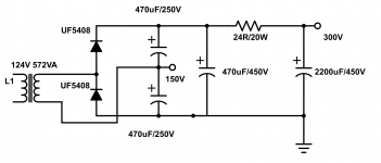
Food for thought, could do a voltage doubler and take the lower capacitor voltage for the screens. Just another way to skin the cat.Really drops more voltage from the power transformer than I expected. Open circuit the Hammond put out around 138V, rectify it and double it (using a voltage doubler to get the high voltage) without a load you get 386Vdc, I was thinking it would drop into the 340V range, more like 310V driving the amp hard. There is a quickie equation to roughly calculate power, not taking into account the tubes, where you double the dc voltage on the plates and divide by the primary impedance.
So with 310V and a 6.6k transformer that gets you, 310*310 / 6600 = 14.5W. You think I would be happy with that call it a day. But the output transformer is a Hammond replacement for the Deluxe Reverb and is rated for 20W. I want my extra 5W. Will not make it a whole lot louder, just make me feel better.
So I rearranged the power transformer. It is a 120/240V to 120V transformer. If instead of hooking up the two primary windings to the wall I put them in series and hook up the 120V secondary to the line I get 208V AC out. This is because Hammond winds their secondaries a little hot, recall I was getting 138V out, so with the 120V going into it I get less than the 240V you would get if transformers were ideal devices.
So take 208V AC, rectify it (multiply by 1.4, which would be the maximum voltage going into a capacitor with no load) which gives us 291, this is going into a doubler so multiply by 2, 2*291 = 582V dc. That is just plain scary. But since I had some significant losses hooked up normally, what the heck let's try it. I have a variac and I can stop turning up the voltage if there is too much voltage. Keep in mind my capacitors in the doubler are 250V so I should be good for 500V.
Well turned it up and without the tubes conducting it got up to 500V. Which is ok for the output section, will have to look at the preamp capacitors later (I forgot about them, I was just watching the output tube current in case they were about to melt). When they started to conduct the voltage went down to 420V, 415V on the plates. So let's see what that should give me for power. The tubes do not swing down to 0V, maybe down to 40V, so 380V. 380*380 / 6600 = 22W. With transformer losses maybe 20W.
I had the bias voltage turned up all the way just in case, going to have to adjust the resistor values as I had 30mA per tube at idle. At 410V*0.030A = 12.3W. The tube plate dissipation is 12W, say 2W of that is going to the screen, about 85% dissipation. A little hot for fixed bias but should be fine until I change the resistors.
Curiosity got the better of me, I really have to order some 500V capacitors to replace the 350V ones. No room to double them up, maybe I can stack them. Other measurement I took, playing at the edge of breakup the voltage drops to 370V, down to 355V with the amp feeding back and gain at a point where more really does not make much difference. All warmed up the plate voltage is now about 400V. No red plating so maybe the tubes will live. Pretty sure I got the most out of the power tubes. Next is to tweak the preamp. and I have yet to add NFB.
Indeed. This same idea was previously mentioned in this thread twice, first in post #17, and again in post #24....could do a voltage doubler and take the lower capacitor voltage for the screens.
At one time, there were independent Australian tube guitar amp manufacturers, and they went their own way with their designs (i.e. they weren't Fender or Marshall copies.) Some of these amps used sweep-tubes for the outputs, and voltage-doubler power supplies to feed them. It was a clever idea, made possible by using then-newfangled silicon diode rectifiers, rather than the older and much more primitive tube rectifiers used in vintage Fenders and Fender copies.
-Gnobuddy
- Status
- This old topic is closed. If you want to reopen this topic, contact a moderator using the "Report Post" button.
- Home
- Live Sound
- Instruments and Amps
- 6dq6 or 6l6gc se amp?