One thing I have noticed during the measurements is that there is some delta between my 12.6VDC and 300VDC grounds in my power supply. But not as big (like 0.2, 0.3 VDC). I'll first try to decrease it to the proper 6.3 (maybe the valve is acting that way taking that much of voltage for the heater), and I'll connect the 300VDC and 6.3VDC grounds together. And I'll surely measure the resistance, and will clean the board better, though the joints don't really look bad to me... Speaking of the soldering — what is the best compound for doing it? I use something which is called Sn99,3Cu0,7 PBFREE.
Last edited:
I'm not surprised, and this is exactly why I don't like the PCB design that grounds the heater to PCB signal ground.One thing I have noticed during the measurements is that there is some delta between my 12.6VDC and 300VDC grounds in my power supply. But not as big (like 0.2, 0.3 VDC).
For preamp valves, heater currents are huge - hundreds of times bigger than anode currents in these valves - and all that heater current flowing through thin copper traces will inevitably drop a little voltage across them (Ohm's law, V = I R).
This isn't much of a problem if the heater current was perfectly noiseless DC. But such a thing doesn't exist. In practice, there will be some ripple and noise in the heater current, even if you're running it from a DC power supply. And that noisy current running through the PCB traces will generate a noise voltage across the length of the PCB trace.
The input triode can't tell noise voltage in its ground from noise voltage at its control grid - it's the difference between control grid voltage and cathode voltage that's amplified.
This means that the noise voltage along the length of the ground PCB trace will be injected into the input triodes, and amplified by them, just like any other input signal. So the whole amp will be much noisier than it should be.

This problem would be much worse if you'd been feeding the heaters with 60-Hz (or 50 Hz) AC, as the designers of the PCB intended. The bad design would inject hum as well as noise into the amps input, where it would be amplified and appear at the output.
So don't do the same thing with your custom PCB! It will be much better to return both heater grounds to a "star ground" at the power supply ground (Google will tell you more about what a star ground is.)
I'll first try to decrease it to the proper 6.3

Your measured data showed more than one volt of DC on each of the four control grids. I can't think of a way that heater over-voltage can cause that symptom, but leaving the control grids floating (bad resistors or bad solder joints) could conceivably cause it (though I have never seen this before!)(maybe the valve is acting that way taking that much of voltage for the heater)
Your ohmmeter will answer this quickly. Just measure resistance from each of the control grids (pins 2 & 7 of each tube) to ground. You should read the same, +/- 5% or so, as the corresponding grid bias resistor (1M or 470k if that's what you used.)
The schematic provided by the Ebay vendor from whom you bought the power supply, shows the 300V and 6.3 V power supplies are already grounded together, on the power supply PCB....I'll connect the 300VDC and 6.3VDC grounds together...
If you add an additional wire connecting these same two points together, you will create a ground loop, which is a bad thing: WTF Are Ground Loops? | Hackaday
I've attached a much more informative write-up on ground-loops from an MIT professor.
Please do!And I'll surely measure the resistance
What you're using is "lead free" solder. It's mandated by law (ROHS regulations) in just about every commercially manufactured product these days, because lead is a poisonous metal.Speaking of the soldering — what is the best compound for doing it? I use something which is called Sn99,3Cu0,7 PBFREE.
However: lead-free solder is much harder to work with at home. Without getting too technical, the lead-free stuff is very unforgiving of the slightest movement between the parts you're soldering, it melts at much higher temperature (damaging components), and it is very easy to make bad (dry) solder joints with it.
Commercially, lead-free soldering is done with accurately computer-temperature-controlled soldering ovens, with a careful ramp-up to exactly the right temperature, and a careful ramp-down back to room temperature.
At home, with a soldering iron in your hand, we cannot recreate such an exact soldering temperature and accurate temperature/time profile. And the result, very often, is poor-quality solder joints.
If you can get hold of it, 60/40 (tin/lead) solder is much, much easier to work with. Here in Canada, I can still buy this for hobby work. I don't know if you can still legally buy it in your country.
There is also 63/37 tin/lead solder, which is a little harder to work with than 60/40, but much easier to work with than the lead-free stuff.
Here is a You Tube video that will tell you more about the problems of using lead-free solder: YouTube
-Gnobuddy
"EST016_Ground_Loops_handout.pdf"
43 pages, 4MB
https://web.mit.edu/jhawk/tmp/p/EST016_Ground_Loops_handout.pdf
43 pages, 4MB
https://web.mit.edu/jhawk/tmp/p/EST016_Ground_Loops_handout.pdf
By the way: I bypassed the grounded heater centre-tap problem entirely by deciding to use two Russian 6N2P valves in my PCB.
These valves are essentially identical to a 12AX7 as far as the guitar signal is concerned, but the heater is different. 6N2Ps have a 6.3V heater wired between pin 4 & 5. The heater has no connection to pin 9 - instead, pin 9 connects to an internal electrostatic shield, which is intended to be grounded.
This neatly solves the problem with grounded heaters in this particular PCB. Pin 9 is grounded, which is exactly what we want for a 6N2P. I supply 6.3V heater power (instead of 12.6 V) to the PCB, which routs it to pins 4 & 5, also exactly what we want!
I've added a pair of 1k resistors across the heater power, and their junction connects to power supply ground, to keep the heaters from floating off to some unwanted arbitrary voltage. The resistors are big enough to keep any substantial heater current from flowing through the PCB traces (there are only about 3 mA of current flowing through those 1k resistors.)
So far, I've only powered my board up long enough to test DC voltages on all pins. All of them seem to be okay, so the next step is to start adding the missing bits (input and output sockets, gain, volume, and tone controls, a channel-switching relay, et cetera.)
-Gnobuddy
I have just got it working!
I have dropped the voltage to 6.3. Connected the board's ground to my 12V supply's ground (so the high voltage supply's output ground is lifted, and the common ground is the one which comes from 220->12 supply). Resoldered the pots (the multiple holes under the caps which as I suppose are designed to accommodate various kinds of capacitors are the friends here — no need to drill the board, just cut the trace between the resistor and the capacitor and use one of those holes).
Now my main problem is that I've sent my Les Paul Junior for the maintenance and the luthier is really busy so that I will get it back in 5 weeks only... Tested with the harmonica microphone a bit, but everybody is sleeping here now so that I can't properly check the sound.
And there is another problem with the pots. I might have overheated them during the resoldering or something else, but they seem to be semibroken (like sometimes you have to hit it a little so that it starts working). I have these: 16mm Variable Resistor Potentiometer Pot Lin Linear Log Logarithmic | eBay (A500K), should they be sufficient? Maybe the wattage should be different.
As for the soldering compound — seems like there is Sn60Pb38Cu2 still available in some stores in Czech Republic. The stores say «for professional use only» — I will see if I will be able to get a little for the future work.
Anyway, I feel much more confident now that my custom board should actually work!
Gnobuddy, thank you so very much for all your help!
I have dropped the voltage to 6.3. Connected the board's ground to my 12V supply's ground (so the high voltage supply's output ground is lifted, and the common ground is the one which comes from 220->12 supply). Resoldered the pots (the multiple holes under the caps which as I suppose are designed to accommodate various kinds of capacitors are the friends here — no need to drill the board, just cut the trace between the resistor and the capacitor and use one of those holes).
Now my main problem is that I've sent my Les Paul Junior for the maintenance and the luthier is really busy so that I will get it back in 5 weeks only... Tested with the harmonica microphone a bit, but everybody is sleeping here now so that I can't properly check the sound
.And there is another problem with the pots. I might have overheated them during the resoldering or something else, but they seem to be semibroken (like sometimes you have to hit it a little so that it starts working). I have these: 16mm Variable Resistor Potentiometer Pot Lin Linear Log Logarithmic | eBay (A500K), should they be sufficient? Maybe the wattage should be different.
As for the soldering compound — seems like there is Sn60Pb38Cu2 still available in some stores in Czech Republic. The stores say «for professional use only» — I will see if I will be able to get a little for the future work.
Anyway, I feel much more confident now that my custom board should actually work!
Gnobuddy, thank you so very much for all your help!
Those are cheap pots, not that I do not have a few my self. I wonder if factory seconds get hawked on EBay, I have had a few where the wiper loses contact with the resistive track, broken connection between the lug and the track, something else that I can't remember. More mechanical issues.
Congratulations!I have just got it working!

Exactly! (I mentioned this back in post #19, page 2.)...the multiple holes under the caps...are the friends here — no need to drill the board, just cut the trace between the resistor and the capacitor and use one of those holes.
You do have to remember to cut the trace on both sides of the board, since the holes are plated-through-hole. I just use a suitably sized drill-bit held between finger and thumb to cut away the copper around one of the through-holes.
Aw, man! That's a long time to have to wait!...my Les Paul Junior...5 weeks...
I have used pots just like that in some projects, and haven't had any problems with them. They don't feel wonderful to turn, though, so I prefer Alpha pots (from Taiwan, but carried by many electronics suppliers, such as Mouser): alpha potentiometers Alpha (Taiwan) Passive Components | Mouser CanadaI have these: 16mm Variable Resistor Potentiometer Pot Lin Linear Log Logarithmic | eBay (A500K), should they be sufficient?
In my experience, Alpha pots have a very nice smooth, precise feel when you turn them, and the cost is not much more than the very cheapest pots, so I use them when I can.
The wattage is probably fine. You may have up to 200 volts peak-to-peak (about 70 volts RMS) from your preamp, but the pots are 470,000 ohms. Power dissipated in the pot (P = V*V/R) is therefore a maximum of 0.010 watts - barely one-hundredth of one watt!Maybe the wattage should be different.
For our purposes (valve preamps), the voltage rating of the pot is more likely to be an issue. The pot could have up to 100 volts (peak) across it at any one instant, and it would be best to use bigger pots that can handle this much voltage with some safety margin.
As an example, the first Alpha pot in that list (Alpha part number RV16AF-10-20R1-B25K-LA) is rated for up to 500 volts.
Two percent copper, huh? I'm not familiar with this type of solder. I've never seen it before. But I think the copper is there to prolong the life of the (copper) soldering iron tip. Other than that, I believe it works pretty much exactly like 60/40 solder (Sn 60 / Pb 40)....Sn60Pb38Cu2...
When I began tinkering with electronics as a small boy, my cheap soldering iron tips used to be made of pure copper, and this material would actually dissolve slowly into the hot solder as you used the iron, so the tip would develop a pit. Every so often, you had to file the tip of the iron to remove the pit, and eventually, the filing would shrink the tip to the point where you had to buy a new tip (or a new soldering iron, because the old tip was corroded solid, and would not come out of the iron!)
In more recent years, all the soldering irons I've used have a copper tip that's iron-plated. The iron plating keeps the tip from dissolving into the solder. As long as you clean the tip gently (and do not sandpaper through the thin iron plating!), the tip doesn't pit.
I think if you have an iron-plated tip, you don't need the 2% copper in the solder. But if that's the only kind of leaded solder you can easily get, go for it. There's no real downside.
You're very welcome! Congratulations on sticking with it until you got it to work, great job!Gnobuddy, thank you so very much for all your help!
-Gnobuddy
Thanks for the pots suggestions! I've done some searching and have ordered a few Bourns which seem to be the opposite of cheap, but not that expensive given that I only need a few. I've favoured Bourns before Alpha because I will also be trying to add that overdrive circuit I've mentioned before, it requires A50K and B100K, and Bourns were the ones I've found A500K, A50K and B100K in the same form-factor (for the consistency of the future boxing).
Next step is to add the Zeners/Resistors part to my current board to see if it works properly with my ADC/DAC part. Right now, when the volume is bigger than something, I get the noise in both of my ADC channels (regardless of the fact that I currently have only one channel connected). Which is of course likely because the level my ADC is capable of taking is less than it takes.
If everything goes well and nothing is lost during the delivery, I will report my progress in a few months (sooner or later if something goes wrong).
And once again — thanks to everybody who has commented on this thread!
One more observation: making a thing yourself gives an interesting imaginary feeling — apart from feeling the instrument, you start to feel it going through the resistors, the heaters and the glass of the valve. The level of intimacy between you and the sound you make increases .
Next step is to add the Zeners/Resistors part to my current board to see if it works properly with my ADC/DAC part. Right now, when the volume is bigger than something, I get the noise in both of my ADC channels (regardless of the fact that I currently have only one channel connected). Which is of course likely because the level my ADC is capable of taking is less than it takes.
If everything goes well and nothing is lost during the delivery, I will report my progress in a few months (sooner or later if something goes wrong
).And once again — thanks to everybody who has commented on this thread!
One more observation: making a thing yourself gives an interesting imaginary feeling — apart from feeling the instrument, you start to feel it going through the resistors, the heaters and the glass of the valve
. The level of intimacy between you and the sound you make increases .
Last edited:
It took me a little bit longer, but I finally have the working preamp! So far I'm pretty happy with the result. Still need to do the software part with the EQ, reverb/delay and speaker simulation (I've got only a ADC-DAC pass through so far), but even without those the sound is rather satisfying. Gnobuddy, thank you once again for the suggestions! Do you have a name, by the way? In my head I would refer to a real person who helped me .
A few comments.
I've tried both 2.7K and 1.5K cathode resistors. Settled on the 1.5K one. 2.7K sounds more soapy to me and 1.5K sounds crispier (whatever it means, just my reflection on the feeling).
About my 4.3V zeners. I've found out that my ADC supports maximum 3Vp-p at the input. Whenever I was going gainier, I was getting a nasty dirt in the second (not yet connected) ADC channel. I tried to lower the zeners value, but 1.5V zeners (to get 3Vp-p) don't exist, I tried 3V zeners. Two observations. They are still not enough to limit the output enough. And they worsen the sound a lot at high gain, I suppose because they clip the sine wave too early and the sound becomes unpleasantly distorted. So, I've added a voltage divider (made of two resistors). And with the overdrive pedal and high gain/volume I still hear that unpleasant distortion coming from the zeners clipping the signal. So my plan is to put even higher value zeners (like 5V or 6V) and adjust the output voltage divider resistors accordingly so that they let only 3Vp-p through.
Other than that, I've tried that Ragemaster circuit with the Germanium transistor, the sound is really cool but extremely noisy (I've tried two types of transistors and I don't think I want to keep looking for the right one with the perfect parameters). Going to try a JFET preamp (FET Preamplifier, part 2) instead.
And thanks again! It feels like I really have a chance to get what I initially wanted.
.A few comments.
I've tried both 2.7K and 1.5K cathode resistors. Settled on the 1.5K one. 2.7K sounds more soapy to me and 1.5K sounds crispier (whatever it means, just my reflection on the feeling).
About my 4.3V zeners. I've found out that my ADC supports maximum 3Vp-p at the input. Whenever I was going gainier, I was getting a nasty dirt in the second (not yet connected) ADC channel. I tried to lower the zeners value, but 1.5V zeners (to get 3Vp-p) don't exist, I tried 3V zeners. Two observations. They are still not enough to limit the output enough. And they worsen the sound a lot at high gain, I suppose because they clip the sine wave too early and the sound becomes unpleasantly distorted. So, I've added a voltage divider (made of two resistors). And with the overdrive pedal and high gain/volume I still hear that unpleasant distortion coming from the zeners clipping the signal. So my plan is to put even higher value zeners (like 5V or 6V) and adjust the output voltage divider resistors accordingly so that they let only 3Vp-p through.
Other than that, I've tried that Ragemaster circuit with the Germanium transistor, the sound is really cool but extremely noisy (I've tried two types of transistors and I don't think I want to keep looking for the right one with the perfect parameters). Going to try a JFET preamp (FET Preamplifier, part 2) instead.
And thanks again! It feels like I really have a chance to get what I initially wanted.
1.5k is "centre biased", and gives you lower distortion and more clean headroom before clipping. More Hi-Fi, less "tubey". Leo Fender used 1.5k a lot, most probably taken directly from the example circuits in the GE or RCA tube catalogues....cathode resistors...2.7K sounds more soapy to me and 1.5K sounds crispier.
So only 1.5 volts peak. Yes, that's too low for a zener diode!...my ADC supports maximum 3Vp-p at the input.
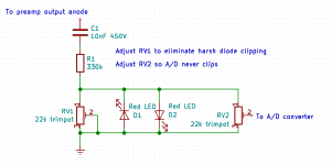
However, an ordinary red LED (usually about 1.4 - 1.8 volts) or two or three ordinary silicon small-signal diodes in series (about 1.5 - 1.8 volts) is a simple alternative.
The attached image shows my suggested circuit. The 330k resistor and first 22k trimpot (RV1) lower the dangerously high voltage from the tube's anode to a level fairly close to the LED threshold, while the second 22k trimpot (RV2) lowers the signal from the LEDs to less than 3 Vpp, to keep the ADC out of clipping.
To use, first adjust RV2 to a very low setting, low enough to guarantee the ADC doesn't clip.
Then increase RV1 to maximum resistance, and play a strong signal into the tube preamp input. You should hear harsh solid-state clipping from the two RED LEDs. Gradually decrease RV1 until the harsh clipping just disappears, leaving only tube clipping from the 12AX7.
Now go back to RV2, and gradually increase it until the ADC just starts to clip, then back RV2 down a little.
I do have a name, of course, but I prefer to keep it off the Internet as much as possible. There are far too many nasty online entities working hard to steal as much of our personal information as possible, and to use it against us. So why make it even easier for them by giving them my name?
The second image attached below shows about a dozen nasty websites trying to spy on my Web browser at this very moment, as I'm typing this post into diyAudio. All those red circles are known tracking sites...and most of the grey ones have no business spying on my browser, so they're probably tracking sites as well.
Please note that I'm not suggesting that diyAudio itself is doing anything nasty. The nasties currently trying to track and spy on me include gstatic.com, newrelic.com, and a number of Google sub-domains, all surely reporting back to the One Tracker To Rule Them All, Google itself.
-Gnobuddy
Attachments
No problem at all. Privacy is sacred if a person wants to keep it. I also would suggest Brave (Secure, Fast & Private Web Browser with Adblocker | Brave Browser) browser. It has a ******** cutter built in (cuts the trackers, the ads and things like that).
Do you think there are advantages of the circuit you've given comparing to the resistor limiter? It's just two zeners plus two resistors seem to be easier.
My logic is that if I choose the right zeners, I will have a known maximum output limit, from that maximum limit I can just calculate the resistor for the voltage divider (for example, if I have 6V zeners, I have 12Vp-p maximum output, then it's 30K and 10K resistors, to get 3Vp-p and keep the same 10K impedance).
Thanks for the suggestion! I'll definitely look into it....Brave...
At first glance, Brave is built off Chrome, which gives me no confidence at all. Not that long ago a security researcher found that, during a two-week time span, Google Chrome planted over eleven thousand more tracker cookies on his computer than Firefox did.
(Story here: https://www.washingtonpost.com/tech...become-surveillance-software-its-time-switch/ )
The Washington Post itself has now paywalled that article, but if you know enough about browsers to recommend Brave, you probably also know enough about browsers to read an article behind a paywall!
It's always possible that the Brave development team actually turned the foul sows-ear that is Chrome into the proverbial silk purse, so I'll certainly look into it some more before making a final judgement.
Mind posting your circuit? I can give a more informed opinion if I'm sure exactly what you're planning.Do you think there are advantages of the circuit you've given comparing to the resistor limiter? It's just two zeners plus two resistors...
But making a guess as to what you have in mind, yes, I think there are advantages; I don't think your circuit has any way to extract maximum "tubeyness" from the triode without also getting harsh gritty horridness from the zeners, and I think your circuit may have a bass frequency response that varies wildly with signal level. I may be wrong, as I haven't seen your schematic yet...
Life is rarely that simple in the world of analogue electronics, which is why digital circuitry is usually much simpler to understand....I choose the right zeners I will have a known maximum output limit...if I have 6V zeners, I have 12Vp-p maximum output...
Firstly, you have two zeners in back-to-back series; each one has a voltage drop, so even if one dropped exactly 6V, your total voltage drop would be more than that.
In reality, the zener that's forward-biased will have a voltage drop of somewhere between 0.5 V and 0.7 V, usually, but it will vary with temperature, zener current, and from one manufacturing batch to the next.
The one that's reverse biased may be supposed to conduct at 6V, but in practice, there is quite a soft "knee" to the curve, particularly at the tiny currents used in this circuit (which are far below datasheet minimum zener current specs.); the voltage climbs slowly through the knee as current increases. There is also a tolerance (typically +/- 10%) to that 6V rating, and there is a temperature coefficient as well.
So, even if operating within datasheet current specs, that "6V" circuit might actually give you 5.9 V (5.4V zener + 0.5 V from the second zener), or it might give you as much as 7.3 V (6.6V zener, 0.7V second zener), and both numbers will change with ambient temperature, and with zener current (which means with how hard you drive the tube preamp.)
Since the circuit is actually operating at far lower-than-datasheet currents, real-world voltage drops may differ significantly from the estimates above. Short of measuring it (using a known precision attenuator feeding your ADC, or a 'scope!) it's hard to even guess what you might end up with.
LEDs also have a soft knee, forward voltage isn't even specified, and the same sort of temperature and manufacturing variations occur. But LEDs are less noisy than Zeners, they're probably cheaper than zeners, and the "knee" voltage is (ballpark) closer to what you need. The last few red LEDs I've measured usually dropped around 1.8 volts, plus or minus about 0.1 volt.
Notice that the two LEDs are wired in reverse parallel in the circuit I suggested, and not in reverse series like the zener diode clipper...if you do decide to go with the LED circuit, this is important!
Because ADC clipping sounds utterly horrible, I suggest staying well below 3 Vpp. Staying 6 dB below that is about as far as you should even consider pushing it - that means never applying more than 1.5V pp. (Yup, the MSB in the ADC will never toggle!)...then it's 30K and 10K resistors, to get 3Vp-p
In fact, a rule of thumb for feeding audio to ADCs is to set peaks to 10 dB below clipping. This throws away an unimportant bit or two of resolution, but much more importantly, keeps you from ever hearing that utterly horrible sound of a clipping ADC. When you have 16 or more bits of resolution to play with, this is a very worthwhile tradeoff.
-Gnobuddy
There is a difference between Chrome and Chromium. Chromium is an opensource browser which is initially (and mostly) developed by Google. But since a long time ago it's an opensource browser which is being developed by many parties (for example, Microsoft has recently released a browser on top of Chromium). Chrome is Chromium with Google's proprietary changes. Brave is being led by Brendan Eich, the creator of JavaScript and a former CTO of Mozilla. And preventing malice seems to be their key target/advantage. Yes, it's built on top of Chromium, but that's far from what Chrome might do. I've been using it for several years already and I'm attaching a screenshot of how much it's blocked and how much time it's saved (of course that statistics could be questioned, but I tend to more or less trust it).
But going back to the schematic things. What I currently have looks like:
I suppose I should certainly try your way (luckily I've recently received a pack of variable resistors). Especially if it promises lower noise and better frequency response.
Thanks!
But going back to the schematic things. What I currently have looks like:
Code:
>---|------------[ R 30K ]---|--------------->
    | ZD1 (6V)               |
    ▼                        |
    |                     [ R 10K ]
    ▲                        |
    | ZD2 (6V)               |
>---|------------------------|--------------->
I suppose I should certainly try your way (luckily I've recently received a pack of variable resistors). Especially if it promises lower noise and better frequency response.
Thanks!
Attachments

Ah, a senior moment here on my part. Thanks for the wake-up! I've actually used Chromium, some years ago, but went back to Firefox.There is a difference between Chrome and Chromium.
At any rate, I will install Brave on a test PC and give it a try. Firefox on Xubuntu 18.04 is currently exhibiting a weird bug, it stops reading input from the keyboard a few hours after being launched; maybe a memory leak.
Thanks for the (ASCII) schematic!Code:>---|------------[ R 30K ]---|---------------> | ZD1 (6V) | ▼ | | [ R 10K ] ▲ | | ZD2 (6V) | >---|------------------------|--------------->
Here's the thing: a triode is very linear at small signal amplitudes, so if the signal is very small, there's no "tubey" distortion, and a 12AX7 won't sound any different than a solid-state op-amp. To get audible amounts of "tubey" sound (i.e. distortion), you have to drive the triode until it's spitting out a large signal - tens of volts, and maybe as much as 200 volts peak to peak, roughly speaking (depends on B+ voltage, anode resistor, tube used, etc, etc.)
So what happens if your second triode is spitting out a slightly distorted, "tubey" sounding signal, two hundred volts from peak to peak, and you then brutally throw two 6V zeners across it, as the clipping circuit above does?
Well, you clip the heck out of the signal! Instead of hearing subtle tubey distortion, you hear a crude solid-state fuzz box, like the ones Jimi Hendrix used. The entire point of using a tube is gone, flushed down the toilet; you might as well have used any of a number of $20 fuzz pedals from Ali Express.
The frequency response problem is a secondary one; a 6V zener diode goes from having extremely high resistance (hundreds of thousands of ohms) at, say, 4 volts, to having very little resistance (a few ohms) at, say, 6.2 volts. So the coupling capacitor from the second triode's anode to your zener clipper is "seeing" a load that varies abruptly between hundreds of thousands of ohms, and just a few ohms, twice on every cycle. There will be some sort of average resistance, which will depend on how hard you're clipping the zeners; and that average resistance will set the bass response. The harder you clip the zeners, the less bass will appear at the output.
So the circuit as shown isn't ideal - in fact, it has serious flaws.
But the flaws are not hard to fix. If you want to preserve the "tubey" distortion you worked so hard, and spent so much money and time to achieve, you need to take a different tack - first, allow the second triode to gracefully go all the way up to nearly its maximum output signal (probably around 200 Vpp), while still sending less than 3 Vpp to your ADC.
This means you need attenuation - lots and lots of attenuation, cutting down the signal to maybe one-hundredth of its original size. Because we don't know exactly what the maximum signal out of that triode will be, it's best to have adjustability.
So that's why I've used a big resistor (330k) and a much smaller trimpot (22k).
Having attenuated the signal down to a level that's probably not going to kill the ADC, we now want the finishing touch: a subtle clamping / clipping circuit that only comes into action if the worst is about to happen - if the ADC is about to be overloaded.
That's where the back-to-back LEDs or zeners come in - but we want them to stay off, and do nothing, so they don't generate crude, nasty, solid-state diode clipping distortion. The exception is if the ADC is about to overload, which makes an even nastier noise. In that case, and only in that case, we want the LEDs or zeners to clamp the signal - even nasty diode clipping is not as nasty as ADC clipping!
I'll try and put together an LTSpice simulation and some simulated waveforms for you tomorrow if I can, but I have other stuff I have to do now. Tonight is music jam night...but the snow is falling, and I need to contact my fellow jammers and see if people want to brave the snow tonight, or call the whole thing off.
-Gnobuddy
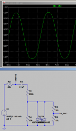
Here are some simulated waveforms to show what I was trying to describe in words yesterday.
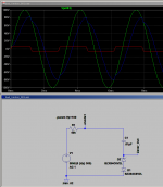
The attached image shows the uncorrupted waveform "inside" the 12AX7 in green. Attaching the two-zener clipper and series coupling cap to the anode distorts the anode waveform into the shape of the blue line at the anode - note the heavy distortion at the points corresponding to zener conduction. (This will sound "buzzy" and harsh.)
Finally, the red waveform shows what comes out of the zener clipper - this is not subtle tube distortion, but rather, crude fuzz-box distortion that owes nothing to the tubes, and everything to the zeners. Harsh and buzzy is probably an understatement for what this will sound like!
The trouble is the huge gap between the 200 Vpp output of the tube, and the 6 - 7 Vpp clipping threshold of the zeners. Without attenuation between those two, the zeners will just clip the heck out of the signal from the second triode's anode.
-Gnobuddy
Attachments
And here's what LTSpice thinks the circuit I proposed in post #52, the one with the resistors, trimpots, and two LEDs.
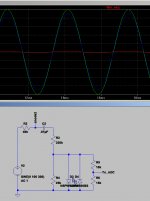
The first image attached to this post shows the same three signals as in the zener clipper. This time, the 330k resistor (R1) prevents LED conduction from causing any nasties in the anode waveform at the triode. Because of this, the blue anode waveform has the same shape as the green "imaginary, inside the tube" waveform.
The second image attached to this post shows only the output waveform to the ADC. There is barely a hint of waveform distortion - the tips of the sine wave are just a bit soggier than they should be. The 22k (or 25k, depending on which country you live in) trimpot has been adjusted to keep the LEDs out of conduction until they're absolutely needed as a last resort. (Note that this is the same signal as the red trace in the previous image - LTSpice picks colours based on how many traces you're graphing, and the very first trace is always green by default.)
Because of the attenuating resistors, the tube preamp can spit out 200 Vpp, and the signal to the ADC is limited to about 2.5 Vpp, but this time, without additional gross solid-state distortion.
In practice, the trimpots would be adjusted using the procedure I outlined in post #52, ideally, using an oscilloscope to supplement fallible and inaccurate human ears.
-Gnobuddy
Attachments
Thank you for it!
I suppose I need to learn to simulate those things myself.
Researching the diode clipping thing, I've found this article: Add Diode-Clipping Distortion to Your Guitar Amp : 6 Steps (with Pictures) - Instructables
It suggests asymmetric clipper with one LED and two diodes. What's appealing to me is that the circuit there promises about 2.7V (1.7V from LED plus 1.05V from two diodes) which seems pretty close to what I want. And it says that asymmetric clipping is more tubey. What do you think?
And one thought about additional adjustable 22K after the 330K. I will certainly swap my 180K with 330K (already ordered the resistors). But I also already have a master volume knob at the output of my preamp. I suppose it should do the adjustment too, shouldn't it? The diode clipping will protect the ADC, and if there is too much unpleasant clipping, I could just roll the master volume of the preamp down a bit. Just trying to optimize for the minimal set of changes.
You might enjoy it. Even though I've been learning and building electronics for a long time now, I only started messing with LTSpice two or three years ago, and I found it extremely useful. The diode clipper screenshots I posted are a good example - there is no convenient way to calculate those waveforms by hand, without some version of SPICE or its many derivatives.I suppose I need to learn to simulate those things myself.
LTSpice is proprietary and closed-source, but you don't have to pay to download it, so if you don't like it, at least it won't cost you any money to try it out.
Philosophically, we're talking about two completely different things....diode clipping...asymmetric clipper with one LED and two diodes...
Thing one: I've built a tube preamp, I want to hear tube distortion, and I don't want to hear any other unwanted source of distortion at all, least of all, crude diode clipping.
Thing two: I want some distortion, and I don't mind if its harsh and buzzy. Diodes are cheaper and easier than tubes, so I'm just going to put some diodes in a solid-state circuit.
Only you know which of the two you're after.
I assumed you were after the first, as you went to quite a lot of trouble to build and troubleshoot your tube preamp. If what you want is solid-state distortion, there are literally hundreds of affordable guitar pedals that will provide harsh diode distortion. No need to bother with tubes, high voltage, and all those complications.For me, the point of tube distortion that it's relatively subtle, that it responds to playing dynamics, that my guitar still sounds like a guitar. But plenty of guitarists are quite happy with solid-state distortion pedals, or want very high levels of distortion, at which point tubes and diodes both start to sound the same to me.
Honestly, I have never heard semiconductor diodes sound anything like a tube. To me they almost always sound harsh and unpleasant. In my younger days, before I ever saw a tube, I must have tried fifty times or more to come up with a nice-sounding distortion using diodes. I never succeeded....it says that asymmetric clipping is more tubey. What do you think?
For me, it's the same with the hundreds of commercially available diode-clipper guitar FX pedals on the market. Almost all of them sound harsh and unpleasant to me, to varying degrees. The ones that sound less harsh usually don't use clipping diodes (like the old Wampler Plexi-Drive, which used three JFETs.)
David Gilmour managed to get gorgeous sounds out of an EHX Big Muff (along with delay, a Chandler tube driver, etc, etc), so we know that one person out of 8 billion can actually make clipping diodes sound good.
This is the trouble with not having a schematic of what you're actually building.But I also already have a master volume knob at the output of my preamp.

If you could hand-draw a schematic you've actually built, complete with all pots, photograph it, and post it, it would help to avoid some of these dead-ends.
So: where have you placed your master volume? What is it intended to do?
In the original application decades ago, the master volume let the preamp generate distortion independently of the power amplifier.
But you're digitizing the output of your tube preamp. Either you're planning to feed the digital signal direct to a computer, or you're going to use a D/A to convert it back to audio after your DSP filtering, and that audio will drive the power amp. That's where the master volume should go, after your D/A, no?
I don't think it should be between ADC and tube preamp; if you turn down the master volume and also drive the tubes gently to get clean tones, you'll get poor bit resolution from the ADC. There is also the problem with matching the high output impedance of the tube to the low input impedance of the ADC. And finally, if you turn up your master volume too high, your ADC will clip and distort harshly, or the carefully designed subtle diode protection circuit will have all the subtlety removed, and become a harsh diode clipper.
I think the way to do it is: tube pre, trimmable attenuator, protection diodes, ADC, your custom DSP filters, DAC, master volume, power amp.
Am I misunderstanding your intentions in some way?
-Gnobuddy
- Status
- This old topic is closed. If you want to reopen this topic, contact a moderator using the "Report Post" button.
- Home
- Live Sound
- Instruments and Amps
- Modifying a 12ax7 HiFi valve preamp to be a guitar preamp