Hi,
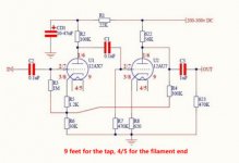
I've got a HiFi stereo preamp with two 12ax7 valves. Attaching the schematics (the schematics uses 12au7 as the second valve, but I've put 12ax7 there as well, they seem to be compatible and 12ax7 gives more gain), it shows one channel.
I want to make a guitar preamplifier from it. I've been looking at some guitar preamp schemes on the internet and it seems like I mostly need to change some resistors (to the ones with the lower resistance), but as I'm not really experienced in the area, I am asking for advice.
The goal is to keep the preamp stereo and have two independent channels for two different instruments, and feed the result to a DAC (to digitally process it further).
Another thing I want is to supply each channel with two potentiometers: one for the gain (between the valves?), another one for the master volume (after the valves). To go from reasobably clean to reasonably crunchy being able to maintain the proper output level.
Could you recommend which resistors need to be changed? As for the gain and master volume I want to replace the two 470K resistors from the scheme, with 1M log pots — are these the correct targets for gain and volume?
Needless to say that as it is it works when I connect something like the headphones output, but when I try to connect the guitar, I cannot hear it.
I would appreciate any advice.
Attachments
R4 foils attempts to get good gain control between stages.
The low impedance of a ADC (not DAC) is a heavy load for a vacuum tube or a 1Meg(!) pot.
Oh, sorry, of course I was meaning the ADC. The way it is now, my ADC takes the output from the preamp when I connect the headphones output from my phone to the preamp's input just fine. I've set up an ADC-DAC pass through and when I put the preamp before the ADC — I get the pass through thing working ok.
That same pass through thing is silent with the guitar is connected to it.
Could you please advice? First thinking about your response is maybe like Klon Buffer (Guitar FX Layouts: Klon Buffer) in between the preamp's output and the ADC?
As I was saying before I'm not very experienced in the area. I might be asking pretty stupid questions because of it
") . It's just the guitar amp schemes seem pretty similar to what I have in that preamp. And I've seen 1M pots in the places of gain and volume...
. It's just the guitar amp schemes seem pretty similar to what I have in that preamp. And I've seen 1M pots in the places of gain and volume...Guitar amp preamps are quite different from that circuit. It (unlike them) has been designed for low gain. You could use the same valves and some of the same components to make a guitar preamp, but that circuit is not the place to start from.
That's my main problem — lack of experience. I can reuse some basic working thing, but building it from scratch might be above my head. For that one I have the PCB with all the components properly labelled (I've got a quite reasonably cheap DIY kit from eBay).
When I look at something like https://www.audiotinker.com/support-files/12l8gt-se-12ax7-reva.pdf, I can find similarity (of course to my limited experience extent). I'm totally fine with resoldering all resistors on that PCB, but I would really try to reuse the PCB if possible.
Last edited:
Hi,
I've got a HiFi stereo preamp with two 12ax7 valves. Attaching the schematics (the schematics uses 12au7 as the second valve, but I've put 12ax7 there as well, they seem to be compatible and 12ax7 gives more gain), it shows one channel.
I want to make a guitar preamplifier from it. I've been looking at some guitar preamp schemes on the internet and it seems like I mostly need to change some resistors (to the ones with the lower resistance), but as I'm not really experienced in the area, I am asking for advice.
The goal is to keep the preamp stereo and have two independent channels for two different instruments, and feed the result to a DAC (to digitally process it further).
Another thing I want is to supply each channel with two potentiometers: one for the gain (between the valves?), another one for the master volume (after the valves). To go from reasobably clean to reasonably crunchy being able to maintain the proper output level.
Could you recommend which resistors need to be changed? As for the gain and master volume I want to replace the two 470K resistors from the scheme, with 1M log pots — are these the correct targets for gain and volume?
Needless to say that as it is it works when I connect something like the headphones output, but when I try to connect the guitar, I cannot hear it.
I would appreciate any advice.
Shortest path to what you want:
* short R6 (replace it with a wire link)
* remove R4
* replace 12AU7 with 12AX7
* make its plate and cathode resistors same as on 12AX7 on the left
* Replace R7 with an Audio/Log 500 k pot.
Of course, if that is a Hi Fi Stereo Preamp, make 2 (mono) Guitar preamps, no use for Stereo there, so use 2 separate single pots, label them Ch1 and Ch2.
Those are Volume/Gain/Drive pots.
* Replace "623"
with again 2 500k Audio pots, label them Master 1 and 2 respectively.You will need to drill 4 pot holes in your chassis, plus needed In-Out jacks.
I suggest your front panel layout as:
Ch1 Input Jack, Volume/Gain, Master ; then Ch2: same thing.
Safety precaution: how much can the following stage (DAC or Preamp) take?
This tube preamp can easily put out 60 to 90V RMS; enough to NUKE anything after it (unless it´s a tube grid); so I suggest you add some 4V or so Zeners in parallel with output, in series but opposite ways, so peaks never reach 5V, which should be safe.
Shortest path to what you want:
* short R6 (replace it with a wire link)
* remove R4
* replace 12AU7 with 12AX7
* make its plate and cathode resistors same as on 12AX7 on the left
* Replace R7 with an Audio/Log 500 k pot.
Of course, if that is a Hi Fi Stereo Preamp, make 2 (mono) Guitar preamps, no use for Stereo there, so use 2 separate single pots, label them Ch1 and Ch2.
Those are Volume/Gain/Drive pots.
* Replace "623"
You will need to drill 4 pot holes in your chassis, plus needed In-Out jacks.
I suggest your front panel layout as:
Ch1 Input Jack, Volume/Gain, Master ; then Ch2: same thing.
Safety precaution: how much can the following stage (DAC or Preamp) take?
This tube preamp can easily put out 60 to 90V RMS; enough to NUKE anything after it (unless it´s a tube grid); so I suggest you add some 4V or so Zeners in parallel with output, in series but opposite ways, so peaks never reach 5V, which should be safe.
OMG! Thank you SO very much! I will research about what Zeners are and will try to rewire as you have suggested.
As for the ADC (I have written DAC by mistake, I'm so eager to get to the DAC stage that I've forgotten that I haven't even reached the ADC yet
), I have a cheap PCM1808 board (PCM1808 Audio Stereo ADC Single-Ended Decoder 24bit Amplifier Board Player Modul | eBay), if I'm reading the chip's spec correctly, it has 6.5V as absolute maximum, so 60 to 90V possible range definitely needs limiting.Thank you once again!
Shortest path to what you want:
* short R6 (replace it with a wire link)
* remove R4
* replace 12AU7 with 12AX7
* make its plate and cathode resistors same as on 12AX7 on the left
* Replace R7 with an Audio/Log 500 k pot.
Of course, if that is a Hi Fi Stereo Preamp, make 2 (mono) Guitar preamps, no use for Stereo there, so use 2 separate single pots, label them Ch1 and Ch2.
Those are Volume/Gain/Drive pots.
* Replace "623"
You will need to drill 4 pot holes in your chassis, plus needed In-Out jacks.
I suggest your front panel layout as:
Ch1 Input Jack, Volume/Gain, Master ; then Ch2: same thing.
Safety precaution: how much can the following stage (DAC or Preamp) take?
This tube preamp can easily put out 60 to 90V RMS; enough to NUKE anything after it (unless it´s a tube grid); so I suggest you add some 4V or so Zeners in parallel with output, in series but opposite ways, so peaks never reach 5V, which should be safe.
One additional question about the plate resistors. There is R1 there, should I short it too? Otherwise putting the same 100K resistor for the second valve won't really be the same.
And one more little question. Is it safe to try the modifications on the one channel only keeping the second one in the original state (in order to try the changes step by step and not all at once). I suppose it should be fine, but not really sure how the valve behaves when one part of it operates with much higher gain than the second one..
Well, you just stole my thunder. Drat!...a HiFi stereo preamp...I want to make a guitar preamplifier from it.
I bought the same PCB a little while ago, with exactly the same intention as you - turning it into a guitar preamp.
While I have zero interest in tube Hi-Fi, what I saw was four independent tube gain stages on an affordable PCB - a PCB with big fat traces and lots of empty real-estate for easy modifications. That looked like an opportunity for a relatively easy conversion.
I've done some work on my project already (both design and construction), and was planning to start a thread about it once I'd got it working.
Now that you've started down exactly the same road, I'm not sure if I should just jump into your thread, or start an independent one to reduce confusion - while we have the same starting point and the same final goal, we're not taking the same road from A to B.
Incidentally, if you haven't started soldering up your PCB already, may I recommend checking if your tube sockets will actually accept tubes before you solder them in?
The sockets I got with my PCB are junk, and unfortunately, I found out after I'd already soldered them into the PCB. I managed to force my two preamp tubes into the sockets using a terrifying (and very unwise) amount of force, which was a stupid move on my part, the sort of thing you do at 1 AM when you've spent hours on a project and don't want to face the fact that you really need to stop, and take a step back, and start over.
At some point I'm going to have to de-solder and remove the useless tube sockets that came with my PCB, and then find some good tube sockets, then solder those in.
There were a handful of gigantic clown-sized film capacitors that also came with my PCB, in what seem to be semi-random, and very hard to read, values, printed in silver ink on a pale blue background.
Most or all those capacitors were quite useless for the guitar preamp design I came up with. So I've put them in a Ziplock bag in case I'm attacked by very small zombies some day, and need some small projectiles to throw at them...
-Gnobuddy
Incidentally, if you haven't started soldering up your PCB already, may I recommend checking if your tube sockets will actually accept tubes before you solder them in?
The sockets I got with my PCB are junk, and unfortunately, I found out after I'd already soldered them into the PCB. I managed to force my two preamp tubes into the sockets using a terrifying (and very unwise) amount of force, which was a stupid move on my part, the sort of thing you do at 1 AM when you've spent hours on a project and don't want to face the fact that you really need to stop, and take a step back, and start over.
My kit seems to have nice sockets (at least they are nice visually) — ceramic with gold-plated pins. And I have a black board and all the writings are clearly visible. I have already soldered the whole thing (to test if it works) and it seems to work ok.
Now I will try to augment it according to the help above.
I have a clarifying question about the Zener diodes. @JMFahey has pointed out that if I will use two 4V diodes, the limit will be 5V. How to calculate that difference? I mean what will be the limit if I use 4.7V Zeners?
The second part is about the Zeners wattage. What should it be? I'm looking at 4,7V/5W right now.
And my third question is about the wiring. The way I understand it, it will be like:
Is that correct?
The second part is about the Zeners wattage. What should it be? I'm looking at 4,7V/5W right now.
And my third question is about the wiring. The way I understand it, it will be like:
Code:
Left Ch -----------> ADC Left
         __|__   |
         \   /  / \
          \ /  /___\
           |     |
Ground ------------> ADC Ground
         __|__   |
         \   /  / \
          \ /  /___\
           |     |
Right Ch ----------> ADC Right
Is that correct?
Back-to-back zeners need to be in series, otherwise you have just ordinary diode behaviour,
since zeners have conventional forward voltage drops.
You mean like this?
Code:
Left Ch -----------> ADC Left
         __|__
         \   /
          \ /
           |
           |
          / \
         /___\
           |
Ground ------------> ADC Ground
         __|__
         \   /
          \ /
           |
           |
          / \
         /___\
           |
Right Ch ----------> ADC RightMine looked the same, but the sockets are too tight for the actual tube pins, so the tube is extremely hard to insert into the socket. And I mean extremely hard!at least they are nice visually, ceramic with gold-plated pins.
I take it you did not have this problem?
The PCB itself was as you describe - black, with lots of lettering. The PCB itself seems fine, good quality, without any obvious flaws. I don't regret buying the PCB.And I have a black board and all the writings are clearly visible.
It was some of the capacitors that were impossible to read. Some of my caps were pale blue, with faint and partly worn silver lettering. I couldn't even read them with a bright light and a magnifying lens, so I had to fish out a capacitance meter to find out what value they were.
Good luck with your project!Now I will try to augment it according to the help above.
-Gnobuddy
The sockets are tight, but not impossibly tight. I suppose they should be tight. For example, the sockets in my Fender Blues Junior are tight as well. In the end it's 300 volts there, yes with the low current, but still doesn't sound like a joke to me .
As for the caps, they are actually the reason why I ordered that particular board. I was watching some Youtube video about valve amp construction and the guy was putting similar caps. And those huge yellow ones as well saying something like «we need something big especially if we deal with the guitar». I couldn't find a guitar preamp kit, so I was going for other options with 12ax7, and in that one I saw the same big yellow caps, which made me hoping that the chances to covert that particular kit are above zero. And all the shapes are printed on the board and there are only 3 types of caps in the kit (one single cap has polarity, two yellow caps at the output and just four exactly the same blue caps), and it seemed rather obvious.
I've ordered the missing resistors and the Zeners, really hope it won't blow up and will give the expected result.
.As for the caps, they are actually the reason why I ordered that particular board. I was watching some Youtube video about valve amp construction and the guy was putting similar caps. And those huge yellow ones as well saying something like «we need something big especially if we deal with the guitar». I couldn't find a guitar preamp kit, so I was going for other options with 12ax7, and in that one I saw the same big yellow caps, which made me hoping that the chances to covert that particular kit are above zero. And all the shapes are printed on the board and there are only 3 types of caps in the kit (one single cap has polarity, two yellow caps at the output and just four exactly the same blue caps), and it seemed rather obvious.
I've ordered the missing resistors and the Zeners, really hope it won't blow up and will give the expected result.
Last edited:
In that case, I was less lucky than you. My sockets are impossibly tight....not impossibly tight...
And yes, I've used plenty of other tube sockets before, and I owned a Fender Blues Junior for a month or so. I still own two other Fender tube amps. None of them have the impossibly tight sockets that came with my Ebay PCB.
That claim is complete nonsense. Unfortunately, there's a lot of nonsense on the Internet about guitars and tube amps (and thousands of other things, too.)... saying something like «we need something big especially if we deal with the guitar».
The gigantic clown-sized capacitors will work fine, if they happen to be the right values for your preamp. Most of the time, guitar preamps use much smaller-value caps than Hi-Fi preamps, for many reasons. For starters, a guitar in standard tuning doesn't go below 83 Hz, while Hi-Fi preamps are expected to go well below 10 Hz.
In my case, none of the huge film caps is a useful value, so I set them aside in case of zombie-hamster attacks.
This is largely because of another guitar-related superstition: many guitar techs and DIY hobbyists believe that PCBs are bad, and turret-boards and tag-strips are good. Because of this, the market for guitar preamp PCBs is small. That's why you don't find too many kits for them.I couldn't find a guitar preamp kit
Your hopes are correct, but not because of the clown-sized caps. This PCB is large, uses fat traces with lots of space between them, and accepts two 12AX7 tubes. All this means it is a good starting point for our purposes, and is easy to modify where that's needed....which made me hoping that the chances to covert that particular kit are above zero.
I have two different types of matchbox-sized film caps. The values are close to each other, but not the same. I don't have the kit with me right now, but IIRC two are pale blue, and two are pale purple....just four exactly the same blue caps...
There is no logical reason for the particular cap values I measured. But there is no logical reason for tube Hi-Fi either, so I guess I shouldn't be too surprised.
J.M. Fahey knows what he's doing - he has been building and selling his own guitar amps in Argentina for decades. If you follow his advice and don't make mistakes, you will certainly end up with a working tube guitar preamp.really hope it won't blow up and will give the expected result.
If you do make mistakes, you can trouble-shoot and fix most of them. Most mistakes won't actually blow anything up, though a few will. (Make sure electrolytic filter caps are oriented the right way round - reverse polarity will actually blow them up!)
By the way, one thing on the actual PCB isn't shown on that little schematic you posted. The heater centre-tap for both the 12AX7 tubes is grounded on the PCB itself. So don't ground whatever heater power you use - leave it floating, the PCB will enforce the ground.
I heard about this PCB in a different thread some few weeks ago. Mine took a few weeks to get from China to British Columbia. During some of that time I thought about what I wanted to do with it once it arrived, and after some head-scratching, I decided to try to build a two-channel preamp with a clean channel and an overdrive channel.
So I have a different plan for my PCB conversion than the one Fahey suggested to you. It's a bit more complicated to implement. I had to cut a few traces on my PCB, solder a couple of jumper wires, and make a few other changes.
Thanks to the clown-sized coupling caps and the long strings of plated-through holes in the PCB, these changes were pretty easy to make.
I haven't had time to apply power and test, and I don't know if my crappy tube sockets are actually making good electrical contact. So it's possible that I may have to remove and replace the tube sockets.
Back to this particular PCB, there are still more possibilities with it. This PCB has four triode gain stages on it, so it can be turned into a complete Fender Princeton (not Princeton Reverb), from input jack right up to power tube grids. There are enough triodes for the entire preamp and the cathodyne phase splitter all to be included on the PCB. Mount two 6V6 on the chassis, wire them to this PCB, and there you have the whole amp!
-Gnobuddy
Thanks for the detailed responses!
My plan is to make a box to go straight into the PA via the looper pedal with two different instruments (guitar and harmonica with the guitar level mic) and with small footprint. I can't afford both physically (it would be too big and heavy) and financially to have two amps, plus I want to be able to loop both. So I want to use that preamp, then go digital to do reverbs/delays/EQs (also hopefully impulse responses for the proper speaker emulation), then back analog into the looper/PA
My plan is to make a box to go straight into the PA via the looper pedal with two different instruments (guitar and harmonica with the guitar level mic) and with small footprint. I can't afford both physically (it would be too big and heavy) and financially to have two amps, plus I want to be able to loop both. So I want to use that preamp, then go digital to do reverbs/delays/EQs (also hopefully impulse responses for the proper speaker emulation), then back analog into the looper/PA
- Status
- This old topic is closed. If you want to reopen this topic, contact a moderator using the "Report Post" button.
- Home
- Live Sound
- Instruments and Amps
- Modifying a 12ax7 HiFi valve preamp to be a guitar preamp