Sounds like a plan!My plan is to make a box to go straight into the PA via the looper pedal with two different instruments (guitar and harmonica with the guitar level mic) and with small footprint.
I notice Fahey's scheme didn't include tone controls - what is your plan for those?
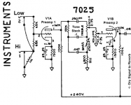
If you want mostly clean tone (with little or no overdrive available), you can insert traditional Fender-type tone controls between your two triode gain stages. The attached image shows how this is done in the Princeton Reverb (a two-knob treble/bass circuit, with no mid control.)
The PCB you and I are using doesn't have room for the extra caps and resistors in the actual tone control circuit, but those three caps and one resistor can be mounted right on the tone control potentiometer tags.
If you want to have more overdrive available, things get a bit more complicated. The scheme Fahey suggested (only a gain pot between the two triodes) will let you overdrive the second triode much more than the Fender Princeton Reverb arrangement. But the tone controls have to go somewhere, and the obvious choice is after the second triode.
The tone stack would then be followed by a master volume, so you can overdrive the second triode and still control the signal level into the later stages of your audio chain.
The thing is, if you do this, you may have issues with impedance matching. The tone stack itself needs to see a high-impedance load, so you'll have to use a high-value master volume pot, 500k or 1M. And that in turn may have too high an output impedance to feed your ADC, unless you put some sort of buffer stage in between. It might be possible to get away with just two resistors that both attenuate the signal down to a safe voltage (for the ADC), and lower the impedance enough, too.
There are many ways to skin...err, pet that cat, if it comes to that. It comes down to whether you want tone controls in the preamp, and whether you want overdrive in the preamp. Once those two decisions are made, you can figure out how to proceed from there.
I have been wondering about this issue as well. I might have to buffer my preamp output and run it into a Hughes & Kettner Red Box, or a DIY equivalent....impulse responses for the proper speaker emulation...
-Gnobuddy
Attachments
I try to be solving problems in the order of their appearance.
I have picked the resistors and Zeners up in the shop today, now need to find a moment to apply them. The next steps really depend on what I will get with what is already suggested. I really hope it will sound about right.
I do just some preliminary thinking.
If I will come to the tone control stage, I would first try to solve it by EQing the thing in the digital domain before assembling a physical circuit. I am a software engineer and reading/writing the code is much easier for me than reading/soldering the schematics. The software EQ could be much more customizable than just the Bass/Tone pair of knobs. But again, I first need to get to that point.
And I will certainly need a fair bit of overdrive, the bluesy/Fendery kind of (so, not too much). Again, I will need to first find out what I will get by augmenting the board with the changes @JMFahey has suggested. I am also considering an overdrive circuit before the preamp (this one with the Germanium transistors looks pretty interesting to me: https://www.seymourduncan.com/tonefiend/guitar/build-the-worlds-wickedest-overdrive-for-under-30/).
And I am not going to put everything on that PCB. I've got an 222 x 146 x 55mm aluminium enclosure, and so far it feels like I might be able to put everything there. Apart from the preamp board: ADC, microcontroller, DAC, LCD screen, power supply, connectors, knobs, voltage converters, unbalanced to balanced audio board (I've got one from eBay) — too many things to be able to put on that PCB anyway. But again only if I will get some promising results with the preamp.
So, I have fingers crossed that it won't be in vain") .
.
I have picked the resistors and Zeners up in the shop today, now need to find a moment to apply them. The next steps really depend on what I will get with what is already suggested. I really hope it will sound about right.
I do just some preliminary thinking.
If I will come to the tone control stage, I would first try to solve it by EQing the thing in the digital domain before assembling a physical circuit. I am a software engineer and reading/writing the code is much easier for me than reading/soldering the schematics. The software EQ could be much more customizable than just the Bass/Tone pair of knobs. But again, I first need to get to that point.
And I will certainly need a fair bit of overdrive, the bluesy/Fendery kind of (so, not too much). Again, I will need to first find out what I will get by augmenting the board with the changes @JMFahey has suggested. I am also considering an overdrive circuit before the preamp (this one with the Germanium transistors looks pretty interesting to me: https://www.seymourduncan.com/tonefiend/guitar/build-the-worlds-wickedest-overdrive-for-under-30/).
And I am not going to put everything on that PCB. I've got an 222 x 146 x 55mm aluminium enclosure, and so far it feels like I might be able to put everything there. Apart from the preamp board: ADC, microcontroller, DAC, LCD screen, power supply, connectors, knobs, voltage converters, unbalanced to balanced audio board (I've got one from eBay) — too many things to be able to put on that PCB anyway. But again only if I will get some promising results with the preamp.
So, I have fingers crossed that it won't be in vain
.Okay, you're planning to put tone controls in the DSP following the second triode. That's certainly do-able.If I will come to the tone control stage, I would first try to solve it by EQing the thing in the digital domain before assembling a physical circuit.
One of my two Fender amps is a Super Champ XD. This is a hybrid amp, with a solid-state preamp, and valve power amp. The preamp is partly analogue (op-amps), and partly digital.
Fender used to publish their own schematic for this amp, so I was able to study it in some detail. In this particular amp, all the controls are implemented digitally: volume, bass, treble, gain, reverb, all of them.
Each of the pots is just wired to a DC reference voltage, and the DC voltage at the pot wiper is read by an ADC, which sends a digital value to the DSP chip, and the chip then applies the appropriate signal processing - more treble, or more bass, etc.
I too have been on both sides of that fence. About twenty years ago, I spent most of two years writing DSP code for the Motorola DSP56000 chip, as part of an active loudspeaker project I was working on. But I enjoy analogue electronics more than code-jockeying.I am a software engineer and reading/writing the code is much easier for me than reading/soldering the schematics.
Watch out for unexpected phase reversals in the audio with some IIR filters. This gave me a few headaches at first, as they would throw the tweeter in or out of phase with the woofer every time I changed the EQ in the code!The software EQ could be much more customizable than just the Bass/Tone pair of knobs.
The rule of thumb is that two gain stages (with a gain pot in between, as Fahey suggested) will give you enough gain to be able to overdrive the second triode a little.And I will certainly need a fair bit of overdrive, the bluesy/Fendery kind of (so, not too much).
If you add an additional overdrive like that DIY Rangemaster, you should certainly be able to get all the overdrive needed for blues. But it might be pretty "fizzy" overdrive, until you get your software EQ figured out.
I'll cross my toes for you.So, I have fingers crossed that it won't be in vain
-Gnobuddy
Two other things to beware ofWatch out for unexpected phase reversals in the audio with some IIR filters. This gave me a few headaches at first, as they would throw the tweeter in or out of phase with the woofer every time I changed the EQ in the code!
a) aliasing. Sounds easy, much, much harder in practice (your "brick wall" filter needs to get below your noise floor
b) digital clipping - that is giving your DAC an "illegal" sequence which results in a post reconstruction value above B+ (if you'll excuse the mixed metaphores)
My update: I feel stupid.
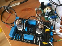
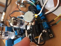
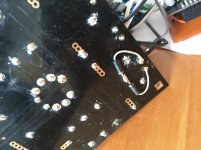
I did everything and all I hear in the result is a loud noise. Attaching three pics of what I have. I am more or less confident with the resistors upgrade. My prime suspects are the pots, I have actually never used them before. I have read that one leg is the input, the second one is the output, third is the ground, but given that the initial resistor was between the signal and the ground, I have joined the two (the closeup for that is on the second picture). I was also suspecting my zeners configuration, but I have tried to remove them from one of the channels with no effect (my zeners config is on the last pic). Don't look at the dirty board and fancy soldering, I will attempt to do a better job if this prototype works.
I am wondering if someone could point out where exactly I am stupid...
Attachments
Firstly, I'm pretty sure you're not even the littlest bit stupid; you had a reasonably creative idea, you walked off the beaten track into an unknown jungle, and now you've got a few thorns in your feet. That's all. No biggie, just pull out the thorns, and get back to walking!I am wondering if someone could point out where exactly...
So: when an entire big circuit with multiple stages doesn't work, it would take a miracle to be able to just intuit where the problem is. Rather, you need to start collecting data, which will eventually lead you to the problem.
The data collection process itself should be methodical, so that we actually learn something at every step.
I'm assuming you've built some sort of power supply for this PCB, though you haven't mentioned it, as far as I can recall. As a starting point, I suggest measuring the DC voltage on every pin of each tube, and listing them here. That will tell us the DC operating conditions for each of the four triodes.
If all the voltages are good, you're ready to move on to the next step in the fault-finding process. But we need that first step, so please measure DC voltages on every pin, and report back.
(All voltages should be measured with respect to ground; connect the black wire from your DMM to the circuit ground, then use the red wire / probe to measure voltages. Remember there are dangerous voltages present when the circuit is operating properly: do not touch the metal end of the DMM probe, wear safety glasses in case sparks fly at your eyes, and if you have them, wear electrician's Class 0 or Class 00 insulating rubber gloves.)
P.S. if you can that see the heaters are lit, you can skip measuring the (AC) voltage on the heater pins. Otherwise, measure the voltages there, too.
P.P.S It looks as though there are only two wires running to each potentiometer - that's definitely wrong, but well fix that later. DC voltages first.
-Gnobuddy
Last edited:
Something that may not be apparent. A circuit with high impedances and gain will pick up stray noise if not in a shielded enclosure. At a minimum I use a piece of sheet metal under an insulator as a ground plane that is attached to the ground of the circuit. Could be as little as a piece of aluminum foil under a piece of cardboard.
Here's how to wire the gain / volume pots. There will be three wires to each pot, not two.
The type of potentiometer usually used for audio has three terminals in a row. One end terminal goes to signal ground; the other end terminal goes to the big audio signal from the preceding amplifier stage. The middle terminal should be connected to the input of the subsequent amplifier stage.
In the attached image has the potentiometer shaft pointing into the screen, away from you. This is important because, if you get the two ends accidentally swapped, the pot will work "backwards", i.e. full volume when counter-clockwise, and zero volume when turned fully clockwise. With a powerful amplifier connected to an efficient guitar speaker, this can result in a very unpleasant surprise, and possible hearing damage.
You can verify your wiring using an ohmmeter (DMM set to read resistance.) Turn the pot shaft fully CCW, with the pot shaft pointing towards you, and measure the resistance between the centre terminal and ground terminal on the pot. Your meter should read near zero, or something very small, compared to the pot resistance. (It's okay if you read 350 ohms on a 500k pot, for instance, as that's less than one part in a thousand.)
-Gnobuddy
Attachments
Good point!A circuit with high impedances and gain will pick up stray noise if not in a shielded enclosure.
Clearly the pots are mis-wired, so I don't know if the second-stage control grid is floating and picking up hum and buzz. I also don't see anything grounding the input, and we don't know under what conditions the OP did his testing (was a guitar plugged in?).
Hopefully more information will trickle in, so that we can help troubleshoot and fix this project.
-Gnobuddy
@Gnobuddy, thanks for the support!
Current status: I've measured the voltages and feel even more stupid now.
About my power supply. Building one myself would have been even harder than the preamp, so, I've got this one: High Voltage DC-DC 150V-420V Converter NIXIE & Tube HV Power Supply 1.25-12V adj 699904388163 | eBay. My main motivation about that particular one is that it takes 12VDC as input. And 12VDC is something I am more familiar with, and I can get a supply which will give me 12VDC from both 110VAC and 220VAC. And it seems to be rather flexible. I've adjusted everything to output a bit above 12VDC for the heater and about 300VDC (as the circuit requires, precisely I have 299VDC) for the plate. That configuration was working with the original circuit.
I've measured the voltages on both tubes and my prior relative confidence about the resistors has completely gone... Here are the DC voltages (with some not particular position of my wrongly wired pots):
The most confusing part to me at this point is the plate voltage differences on the second valve... But the more than twice difference between the first one and the second one is also confusing.
And another clarifying question about the pots. The place of the original 470K resistor has only two contacts — the signal and the ground. Does it mean that I somehow need to do the following to be able to wire the pot properly:
I mean do I need to somehow interrupt the signal to before and after?
Thank you once again! I have no idea what people did before the internet.
Current status: I've measured the voltages and feel even more stupid now
.About my power supply. Building one myself would have been even harder than the preamp, so, I've got this one: High Voltage DC-DC 150V-420V Converter NIXIE & Tube HV Power Supply 1.25-12V adj 699904388163 | eBay. My main motivation about that particular one is that it takes 12VDC as input. And 12VDC is something I am more familiar with, and I can get a supply which will give me 12VDC from both 110VAC and 220VAC. And it seems to be rather flexible. I've adjusted everything to output a bit above 12VDC for the heater and about 300VDC (as the circuit requires, precisely I have 299VDC) for the plate. That configuration was working with the original circuit.
I've measured the voltages on both tubes and my prior relative confidence about the resistors has completely gone... Here are the DC voltages (with some not particular position of my wrongly wired pots):
Code:
Leg      Valve1      Valve2
1        67          149
2        1.10        1.5
3        1.92        1.7
4        12.33       12.33
5        12.33       12.33
6        67          106
7        1.10        1.16
8        1.92        2.28
9        0           0
The most confusing part to me at this point is the plate voltage differences on the second valve... But the more than twice difference between the first one and the second one is also confusing.
And another clarifying question about the pots. The place of the original 470K resistor has only two contacts — the signal and the ground. Does it mean that I somehow need to do the following to be able to wire the pot properly:
Code:
Before:             After:

Signal ---O---      Signal ---O   O---
          |                    \ /
        [470K]               [A500K]
          |                     |
Ground ---O---      Ground -----O-----
I mean do I need to somehow interrupt the signal to before and after?
Thank you once again! I have no idea what people did before the internet
.
Last edited:
That's an interesting power supply, and certainly looks like a good way to go. There's a "However", though!
The PCB I have grounds pin 9 of both valves (a bad design, and not indicated anywhere on the sparse data in the ad for the PCB; I spotted the problem by inspecting the PCB tracks.)
You show zero volts on pin 9 of both valves, so I assume you have exactly the same PCB I have.
Now, pin 9 is the centre-tap of the heater. As the AC symbol (~12.6V) on the PCB suggests, the heater was designed to be fed from a 12.6V winding on a conventional 60-Hz power transformer. One end of the heater would be nominally at (-6.3V AC) when the other end is at (+6.3V AC). Each half of the heater is fed 6.3 V AC RMS; end-to-end, you have 12.6V AC RMS.
However, the 12.6V (adjustable) output of your power supply is not floating - the negative end of the 12.6V supply is grounded, as shown in the Ebay schematic. Therefore you cannot supply +/- 6.3V to the heater. You can only supply 0V and (+something), i.e. only zero and a positive voltage.
This leaves you with only one option: tie pins 4 & 5 together (wire both the "12.6V" wires to the positive end of the DC heater power), and supply them with only 6.3 V DC. NOT 12.6V!
Your voltage readings indicate 0V on pin 9, and +12.6V on both pins 4 and 5. If correct, this means you are applying twice as much voltage to the heater as you should. If so, I'm amazed the heaters haven't already burnt out.
As a visual indicator, heaters should glow a dull red, like embers in a dying wood fire, not bright yellow or white like an incandescent lamp.
So this is priority #1: drop the heater voltage to 6.3V immediately. Unless I've somehow completely misunderstood, your current scheme (double the heater voltage) will destroy both valves in very short order.
On to the rest of the DC voltages - and you are right, just about every single one of them shows something wrong. But let's start with the most problematic ones:
Code:
Leg      Valve1      Valve2
2        [COLOR=red]1.10        1.5[/COLOR]
7 [COLOR=red]1.10 1.16[/COLOR]Now, every one of those grids is tied to ground via a resistor (either 1M or 470k, if you're using the stock values; it doesn't matter if the 470k is a pot, or a fixed resistor.) There is essentially zero current through those resistors, so both ends of the resistor should be at zero volts.
So how can the control grids be at anything other than zero volts? It's hard to tell without being able to inspect your board more closely, but my first two suspects are either bad tube sockets (we talked about this earlier), or dry solder joints, that aren't actually making contact.
You can check the first hypothesis by first removing all power to the circuit, then using your DMM to measure the resistance from each control grid (pin 2 & 7 of each tube right at the base of the tube) to the corresponding solder blob on the underside of the board. If the socket is doing its job, you should measure nearly zero resistance (most DMMs will indicate a fraction of an ohm when there's near-zero resistance between the probes.)
You can check the second hypothesis by measuring resistance (again, without any power applied), on the underside of the board, from the solder blob on pins 2 & 7 of each tube to ground. You should get 1 meg (1000 kilo ohms) for each of the control grids in the input valve, and 470k for each of the two control grids in the second valve.
DC voltages at the anodes (plates) depend very much on the power supply voltage, the value of the cathode resistor, the value of the anode resistor, and the voltage at the control grid. Right now, the last of those is definitely wrong, so that has to be fixed first.The most confusing part to me at this point is the plate voltage differences on the second valve... But the more than twice difference between the first one and the second one is also confusing.
Once all the control grids show zero volts DC, you can re-measure cathode and anode voltages, and that will lead us to the next step in the fault-finding process.
Yes. The original amp design has no pot in between the two gain stages; you have to break the original signal connection from anode of 1st stage to grid of 2nd stage, and insert your pot in between. In this application, the pot is a voltage divider, not a variable resistance....about the pots. The place of the original 470K resistor has only two contacts...I mean do I need to somehow interrupt the signal to before and after?
Fortunately, the ridiculously oversized clown-caps are your friend here, as is the long row of holes provided on the PCB for the far end of the coupling cap (from 1st anode to 2nd grid.) If you throw away the clown-cap, it is easy enough to use a drill bit held between the tips of your fingers to remove the copper around one of the excess holes, breaking that long row of holes into two or three shorter rows insulated from each other. Because this is a double-sided, plated-through-hole PCB, you have to do this on both sides of the board, at the same hole, otherwise continuity won't be broken.
Once this is done, you can now solder a sane-sized capacitor across the gap closest to the anode, and take a wire from the other end of that cap to your pot.
I'll clarify this mod later (I can take some photos of the mods I did on my PCB.) For now, fix the two top-priority issues - the heater voltage, and the mysteriously non-zero control grid voltages!
We went to the library, read dozens of books written by qualified authors and published by reputable publishing houses, and we accumulated deep knowledge slowly, over a period of time.Thank you once again! I have no idea what people did before the internet
And those books contained the accumulated deep knowledge of the author or authors, vetted and curated by her editor, fact-checker, maybe lab technician, etc, so you had a reasonably good reason to trust what was in the book.
I love many things about the Internet, but there is plenty of bad with the good. One of the bad things is that we now tend to have a ten thousand error-filled "facts" from people with little understanding, sharing space with the one or two actual facts from people who know what they're talking about. It's become almost impossible for anyone to get accurate information about audio electronics on the 'Net, because the vast majority of what you find is nonsense.
-Gnobuddy
OMG, thanks for all your input!
I suppose, I didn't burn the valves just because I was switching the thing on for quite short periods of time just to test... I was feeling there is something fishy in my setup. That 12.6V printed on the board... I was reading the 12ax7 specs, and that 6.3V was a bit confusing, not anymore.
And my current state of mind is the following. I now take this board as a very important stepping stone. I've tried and learned much. And reaching my goal board is possible but I feel like there is a better way. With all that new experience, I'm going to try to order my custom PCB (a colleague has told me about seeedstudio.com service which makes it pretty cheap).
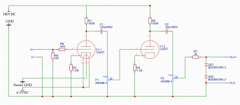
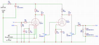
So, I've been sketching my new schematics and I would really appreciate your feedback. I'm attaching the schematics to this message. Basically, it's a hybrid of what I was going to get modifying that DIY kit and a few other things I've read in the past weeks.
In particular I need suggestions about:
R6 — it's not present in this thread's initial schematics, but I've seen it in some other guitar preamps;
R7 — I've read that the resistor is needed in that double Zener clipping circuit and I've taken the value from this video YouTube, but I'm not sure about if it's required in my circuit and if the value is ok, I'm going with 4.3V Zeners;
And about the capacitors — I've taken the .02u/450V value from another guitar preamp. Is it ok? Do I need other caps? What type of capacitor would be the best?
Of course all other necessary corrections would be cool too.
What do you think?
And I won't be tired of saying thank you!
I suppose, I didn't burn the valves just because I was switching the thing on for quite short periods of time just to test... I was feeling there is something fishy in my setup. That 12.6V printed on the board... I was reading the 12ax7 specs, and that 6.3V was a bit confusing, not anymore
.And my current state of mind is the following. I now take this board as a very important stepping stone. I've tried and learned much. And reaching my goal board is possible but I feel like there is a better way. With all that new experience, I'm going to try to order my custom PCB (a colleague has told me about seeedstudio.com service which makes it pretty cheap).
So, I've been sketching my new schematics and I would really appreciate your feedback. I'm attaching the schematics to this message. Basically, it's a hybrid of what I was going to get modifying that DIY kit and a few other things I've read in the past weeks.
In particular I need suggestions about:
R6 — it's not present in this thread's initial schematics, but I've seen it in some other guitar preamps;
R7 — I've read that the resistor is needed in that double Zener clipping circuit and I've taken the value from this video YouTube, but I'm not sure about if it's required in my circuit and if the value is ok, I'm going with 4.3V Zeners;
And about the capacitors — I've taken the .02u/450V value from another guitar preamp. Is it ok? Do I need other caps? What type of capacitor would be the best?
Of course all other necessary corrections would be cool too.
What do you think?
And I won't be tired of saying thank you!
Attachments
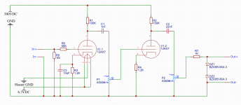
I have updated the schematics a little. Added a 10uF capacitor around the first cathode resistor (in the circuits I've seen it tends to be there more than not to be), updated the output capacitors to 1nF after the first stage and 22nF after the second stage. Also changed the R6 value from 47K to 68K (68K seems to happen much more often). Attaching the picture.
Attachments
You're welcome!OMG, thanks for all your input!
Honestly, I would encourage you to continue to work with this board, at least long enough to fix one channel. Then move on to the next iteration of the project....this board...stepping stone...learned much...
The reason is simple: there is so much more still to be learned from this project! If you find and fix the mistakes you've made on this board, you will learn a tonne. AND that will reduce the number of mistakes you make with your next project, using the custom PCB, so that one will go much better.
If I may get on my soap-box for a second, think about this: a person who doesn't make any mistakes is not learning anything new, because he/she already knows how to do it correctly.
That's so obvious that we should all be aware of it, right? Instead, our extraordinarily dumb popular culture teaches the opposite: that you're a loser if you make a mistake.
That belief is dumb, ego-driven, and completely wrong! A person who makes no mistakes is stuck in place, glued to one spot, learning nothing new. Think about the number of times every single one of us fell down when we were babies learning to stand, and then to walk. If we'd avoided mistakes (falling) then, we would all still be lying on our backs, unable to stand up.
The corollary is obvious: mistakes are a part of learning. If I don't know something, and therefore I make a mistake trying to do it, right there I have the chance to learn, to fix the mistake, and in fixing it, to learn how to do it. Make a mistake, fix it, learn.
But if we make a mistake, and don't fix it - we don't learn as much. We may learn what to avoid (the mistake we already made), but we still don't know how to fix it, to do it the right way, whatever that might be.
This is why I'm encouraging you to finish what you started; fault-find, locate your mistakes, learn how to fix them, until you get at least one triode working properly, and preferably, at least one entire channel of your stereo board.
From my point of view, you have nothing to prove: you've already proven to yourself that you're smart enough to program a computer. So feel free to make lots of mistakes with this valve preamp project, which is a very effective way to learn more in this new (to you) field!
May I suggest you look up the schematic for the AX84 P1 project? You will also find You Tube videos demonstrating the AX84 P1; most are by novice guitarists with untuned guitars who sound terrible, but there are a few by competent musicians that give you an idea how this amp sounds. It's modelled after an early Marshall valve guitar amp, and I have a hunch you might like it better than the Fender-derived one you've been sketching....my new schematics...appreciate your feedback.
Back to your drawing, I've annotated your last schematic, and am attaching the result. But why did I recommend those specific changes? Why lower the input grid stopper from 68k to 10k, for instance? I encourage you to do a little research to find out *why* each of the components in the circuit has the value it has, and how that affects the circuit's behaviour.
I think you need a cathode bypass cap for the second triode, because you want enough voltage gain to generate some distortion, and you have only two gain stages.Do I need other caps?
The truth? Any type of capacitor that has the capacitance value you need, and is rated to withstand the appropriate voltage, is fine.What type of capacitor would be the best?
For big-value cathode bypass caps (like the 10uF you sketched in), there used to be no alternative except for aluminium electrolytic caps. These caps are absolutely fine for the job - inexpensive, proven in millions of audio circuits, and they will last you maybe twenty years.
If twenty years is not enough for you, these days we have an even more durable, alternative: multilayer ceramic caps, like this: https://www.digikey.com/product-detail/en/kemet/C324C106K3R5TA/399-13950-ND/6562361
That particular cap is rated for 25V DC maximum, which is more than enough for the cathode bypass caps in your circuit.
If your pockets are full of money and you want to spend more than you need to on caps, there are "film capacitors", which work better at radio frequencies. They provide no audible benefits in a guitar amp.
There is no need for a 10uF cap in this circuit, by the way; half that value (4.7 uF) is about the biggest you can benefit from in a Fender-style preamp. Newer preamp designs tend to use much smaller capacitors here, to avoid big boomy bass from the guitar, and produce crisper overdrive. The AX84 P1 I mentioned uses 0.68 uF...
-Gnobuddy
Attachments
This is a mistake, which is why I corrected it. 1nF is too small to work with a 500k pot and a guitar; you'll lose most of the bass....updated the output capacitors to 1nF after the first stage
Here's why: https://www.electronics-tutorials.ws/filter/filter_3.html
-Gnobuddy
I will certainly try to make at least one channel work! I have ordered new 12ax7 sockets and a few capacitors from eBay, it usually takes about a month to get them — so I have a space for experiments .
As for making mistakes — making a mistake is totally not my fear. «Failure is always the best way to learn». My only most desperate fear is that I short something bad enough that my wife would notice (like no light in the apartment) — she's very afraid of electrical experiments. For some reason I was never afraid of asking stupid questions. After all, the only person I would want to prove something to is myself. Otherwise I suppose I wouldn't even be here asking all these questions (which are definitely dumb and obvious from a relatively experienced person's perspective). Luckily, there are people like you and JMFahey — the hope that you exist was the most important driver for coming here . Plus I really want to make a musical picture I have in my mind a reality — that's the most important thing for doing it at all.
I've had a quick look at the AX84 P1, and I'll continue to read more about it — thanks for the suggestion! The key thing about Fender vs Marshall to me is that back in the days I've been trying various Marshalls (don't even remember which ones) and for some reason they never sounded satisfactory with the harmonica, while Fenders were the opposite (most of the valve Fenders I've tried fit the harmonica nicely). But that AX84 P1 is a small one, I suppose I've never tried any Marshall like this.
I've upgraded the schematics with your suggestions. Plus I've added a power supply decoupling filter from the AX84 P1 (something similar seems to be present on our board as well, but if I read the schematics correctly, only for the first valve).
About the 68k resistor at the input, I've actually found that article before adding it: Why 68k input resistors for guitar amps?. And my guess about your 10k suggestion is that understanding my wish to get an overdrive, you've increased my input signal level while I will still have some filtering. But that's just a guess.
For the capacitors. For some absolutely irrational weird reason, I really like the looks of those huge yellow capacitors. You might make fun of me, but my guts illogically scream «these are the droids you're looking for!». For that reason I've ordered these for 22nF: 8pc Polypropylene Film Capacitor PPT 0.022uF 1000V K 10% Non Inductive AID Audio | eBay, and these for 1uF (as the AX84 P1 has 1uF): 2pc Polypropylene Film Capacitor PPT 1uF 250V K +-10% Non Inductive AID Audio | eBay. It might be an overkill or a wrong fit, but these are not very expensive (given that I only need a single device for my personal usage), they have the «Polypropylene Film» buzz words, and they are huge and yellow. If those will not work out, I'll just go to the local store to buy whatever is available.
And my current course of actions is the following: trying to get some sound from my current board. When the sockets and the capacitors arrive, try to solder my scheme without PCB, probably readjust and correct something in it, then try to order a PCB for it.
Attaching the updated schematics.
Thank you very much again!
.As for making mistakes — making a mistake is totally not my fear. «Failure is always the best way to learn». My only most desperate fear is that I short something bad enough that my wife would notice (like no light in the apartment) — she's very afraid of electrical experiments
. For some reason I was never afraid of asking stupid questions. After all, the only person I would want to prove something to is myself. Otherwise I suppose I wouldn't even be here asking all these questions (which are definitely dumb and obvious from a relatively experienced person's perspective). Luckily, there are people like you and JMFahey — the hope that you exist was the most important driver for coming here . Plus I really want to make a musical picture I have in my mind a reality — that's the most important thing for doing it at all.I've had a quick look at the AX84 P1, and I'll continue to read more about it — thanks for the suggestion! The key thing about Fender vs Marshall to me is that back in the days I've been trying various Marshalls (don't even remember which ones) and for some reason they never sounded satisfactory with the harmonica, while Fenders were the opposite (most of the valve Fenders I've tried fit the harmonica nicely). But that AX84 P1 is a small one, I suppose I've never tried any Marshall like this.
I've upgraded the schematics with your suggestions. Plus I've added a power supply decoupling filter from the AX84 P1 (something similar seems to be present on our board as well, but if I read the schematics correctly, only for the first valve).
About the 68k resistor at the input, I've actually found that article before adding it: Why 68k input resistors for guitar amps?. And my guess about your 10k suggestion is that understanding my wish to get an overdrive, you've increased my input signal level while I will still have some filtering. But that's just a guess.
For the capacitors. For some absolutely irrational weird reason, I really like the looks of those huge yellow capacitors. You might make fun of me, but my guts illogically scream «these are the droids you're looking for!». For that reason I've ordered these for 22nF: 8pc Polypropylene Film Capacitor PPT 0.022uF 1000V K 10% Non Inductive AID Audio | eBay, and these for 1uF (as the AX84 P1 has 1uF): 2pc Polypropylene Film Capacitor PPT 1uF 250V K +-10% Non Inductive AID Audio | eBay. It might be an overkill or a wrong fit, but these are not very expensive (given that I only need a single device for my personal usage), they have the «Polypropylene Film» buzz words, and they are huge and yellow
. If those will not work out, I'll just go to the local store to buy whatever is available.And my current course of actions is the following: trying to get some sound from my current board. When the sockets and the capacitors arrive, try to solder my scheme without PCB, probably readjust and correct something in it, then try to order a PCB for it.
Attaching the updated schematics.
Thank you very much again!
Attachments
Last edited:
> About the 68k resistor at the input
If you totally digest the Fender 2-Jack network, you will see that the effective resistance in Hi-gain is 34k, not 68k. Not a big difference, but is a small effect.
In Low-gain the guitar is loaded in 136k, which is not the brightest tone around, but the 2:1 divider sufficed to control input-clipping on the early hum-buckers which were not too bright anyway.
In 2-guitar application the 68ks reduce interaction so one axe's Vol knob can't short the other axe too much. This 2-player mode is less used today than in the early 1960s.
I think the two input jacks (Hi / Lo) are essentially irrelevant today. I have never seen a guitarist use the Lo jack.
However: a 33k grid stopper at the input generates more hiss than the entire rest of the amplifier does!
Reducing that input resistor to 10k is believed to provide adequate protection from self-oscillation and radio interference, while reducing the amount of thermal noise to about the level of the input valve itself.
-Gnobuddy
I think the only significant change between the P1 preamp, and the one you've currently sketched, is the value of the input stage cathode resistor (for the first triode in the signal chain.)...that AX84 P1 is a small one...
Fender typically used 1.5k here. Along with a 100k anode resistor, this value produces something called "center bias", which, in a nutshell, makes the preamp very clean, almost Hi-Fi. This might be why you like it for harmonica.
The P1 (and the Marshall from which it came) uses 2.7k for this cathode resistor. This produces a slightly "cold bias", which for our purposes makes more second-harmonic distortion, and a richer (but not as clean) guitar tone.
Since you have two independent channels in this preamp, there is nothing to stop you from using 1.5k in one channel for the harmonica, and 2.7k in the other for the guitar.
No arguing that point. Yes, they certainly are huge and yellow!...they are huge and yellow
Sounds good! First step: find out why the control grids (all four of them) are not at zero volts!And my current course of actions is the following: trying to get some sound from my current board.
It occurs to me that you most likely measured the (non-zero) voltages on the solder blobs under the PCB socket, in which case you actually eliminated the socket-to-valve-pin joint itself as the source of the problem. If this is in fact the case, the remaining most likely culprit is bad solder joints.
Unfortunately the camera has whited-out all the solder joints (the image is overexposed because the solder is bright and reflective), so I can't see whether they look like good soldered joints or not. But you can measure resistance from each of those four control grids to ground, as suggested earlier, and this will tell you if the solder joints are bad.
(There is a tiny possibility of bad - open circuit - grid bias resistors. But all four of them? That's incredibly unlikely. So I prefer the bad solder joint hypothesis, until we have more data to clarify the situation.)
-Gnobuddy
- Status
- This old topic is closed. If you want to reopen this topic, contact a moderator using the "Report Post" button.
- Home
- Live Sound
- Instruments and Amps
- Modifying a 12ax7 HiFi valve preamp to be a guitar preamp