(SOLVED, but still need info for other mods) Fender PR241 Frontman|High pitched noise
Hi to all!
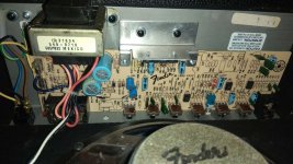
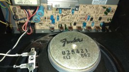
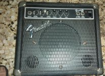
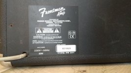
The above mentioned guitar amp was given to me for free. It is an old practice amp made by Fender in Mexico. Says type PR 241 on the sticker on the back and Frontman Amp on the front panel. It consumes 38 Watt and has an 8Ohm loudspeaker, so i suppose it outputs about 15 Watt RMS @8Ohm.
I am trying to repair it (see below), so i can plug an 1x12" cabinet with a speaker like Jensen C12Q or Celestion Vintage 30. If it works OK, i am planning to throw away the factory 8" speaker and cut the amp in half so after modifying it, it will look like an amp head
 .
.
The problem: amp turns on OK, it switches normally between clean and overdrive channel (i can hear the hum noise in OD) but it "screams" (see below) and outputs no audio from the guitar.
When i plug a jack cable in the input, regardless of the guitar being connected or not, when volume is on zero it is quiet, but after trying to set volume at 1 or more then it starts sounding a high-pitched, constant, clear and very loud sound/noise (like a squeal or whine). It is so loud that my head buzzes and my my ears hurt even after i turn it of. My dog gets very stressed from this noise/sound. The sound changes pitch with treble equalizer knob, but other than that it is always stable on max db not dependent on the volume setting, and stops when i set volume to zero (volume/gain in OD mode) or unplug the input jack. With the guitar connected or not, it does the same thing whenever i have a jack plugged in the input of the amp. It does not change if i ground or short circuit the contacts on the other end of the cable, or if i connect and play the guitar. Already tested different good cables and guitars.
Any ideas?
Where should i start from for troubleshooting?
I have a (good) multimeter and some basic skills on desoldering and soldering. I know Physics well too, but i have little practical electronic repair skills.
Also, if anyone could send me any schematics of the board, i would be grateful.
If you need more photos of the amp or the circuit board, just ask for them and i will upload.
Thanks in advance,
Panos.
P.S. Sorry for my poor/not-perfect English, i am from Greece .
.
Hi to all!
The above mentioned guitar amp was given to me for free. It is an old practice amp made by Fender in Mexico. Says type PR 241 on the sticker on the back and Frontman Amp on the front panel. It consumes 38 Watt and has an 8Ohm loudspeaker, so i suppose it outputs about 15 Watt RMS @8Ohm.
I am trying to repair it (see below), so i can plug an 1x12" cabinet with a speaker like Jensen C12Q or Celestion Vintage 30. If it works OK, i am planning to throw away the factory 8" speaker and cut the amp in half so after modifying it, it will look like an amp head
.The problem: amp turns on OK, it switches normally between clean and overdrive channel (i can hear the hum noise in OD) but it "screams" (see below) and outputs no audio from the guitar.
When i plug a jack cable in the input, regardless of the guitar being connected or not, when volume is on zero it is quiet, but after trying to set volume at 1 or more then it starts sounding a high-pitched, constant, clear and very loud sound/noise (like a squeal or whine). It is so loud that my head buzzes and my my ears hurt even after i turn it of. My dog gets very stressed from this noise/sound. The sound changes pitch with treble equalizer knob, but other than that it is always stable on max db not dependent on the volume setting, and stops when i set volume to zero (volume/gain in OD mode) or unplug the input jack. With the guitar connected or not, it does the same thing whenever i have a jack plugged in the input of the amp. It does not change if i ground or short circuit the contacts on the other end of the cable, or if i connect and play the guitar. Already tested different good cables and guitars.
Any ideas?
Where should i start from for troubleshooting?
I have a (good) multimeter and some basic skills on desoldering and soldering. I know Physics well too, but i have little practical electronic repair skills.
Also, if anyone could send me any schematics of the board, i would be grateful.
If you need more photos of the amp or the circuit board, just ask for them and i will upload.
Thanks in advance,
Panos.
P.S. Sorry for my poor/not-perfect English, i am from Greece
.Attachments
-
 IMG_20191009_223233.jpg802.6 KB · Views: 507
 -
 IMG_20191009_223302.jpg823.8 KB · Views: 388
 -
 IMG_20191009_223308.jpg779.7 KB · Views: 394
 -
 IMG_20191009_223205.jpg823 KB · Views: 386
 -
 IMG_20191009_223145.jpg846.4 KB · Views: 508
 -
 IMG_20191003_140335.jpg755.4 KB · Views: 302
 -
 IMG_20191009_223412.jpg806.9 KB · Views: 622
Last edited:
Very loud sounds like this can cause permanent hearing damage - you may find yourself becoming increasingly deaf as the years go by. The symptoms you're describing (buzzing, ears hurting) are part of a medical condition called "TSH" or "Temporary Shift of Hearing", which indicates that your ears have actually been damaged by exposure to this very loud sound. Over time, your ears are recovering at least partially, so the buzzing and pain subside over time.It is so loud that my head buzzes and my my ears hurt even after i turn it of. My dog gets very stressed from this noise/sound.
Repeated exposure to these loud sounds will cause "PSH", Permanent Shift of Hearing, which means your ears will now be permanently damaged, and will not recover. You will have reduced hearing for the rest of your life; you may also have buzzing or ringing or whistling inside your ears for the rest of your life (tinnitus).
So please take precautions. You should not allow yourself to be exposed repeatedly to this very loud sound. As a very simple first step, place your guitar amp face-down on the floor or on a folded blanket or towel during testing, until you cure the problem. If the amp has an open-back cabinet, place a pillow or two over the back, too.
There are more elegant solutions involving adding power resistors between amp and speaker, to temporarily limit the amount of power that can reach the speaker. If you're interested, I can go into those.
But whatever you do, please PROTECT YOUR EARS. They have to last you a lifetime. Deafness and tinnitus are incapacitating medical conditions - please don't want to inflict them on yourself!
-Gnobuddy
Thanks guyz, i will definitely start with the input jack and it's joints on the board. I will keep you updated.
Do you guys know any other components that tend to fail, showing the above described symptoms? Any other ideas?
Can someone explain or give me some link on this: Why a mono jack has four points at the bottom for the PCB (as i see from fender parts) when only 2 are needed for signal and ground?? The other two, are they some kind of on-off switch, are they unused or what else?
Board schematics still needed to educate me, helping me understand exactly how my amp board works.
Gnobuddy you are absolutely right! Safety first. Only excuse i have is that i did not know the actual problem when i first checked. My friend that gave it away did not tell me exactly the problem. I was shocked! Next time i will be wearing earplugs.
My (old) dog that is 99% deaf, heard the noise and she went away to hide!
My right ear is a little deaf, after almost a decade of gigging in studio with the band, 1-2 meters (3-6.5 feet) away from a double 4x12 stack of Marshall cabs with no protection...
With the fender frontman, i felt "strange" for 1-2 minutes yesterday. Today i feel totally fine. I hope that i fully recovered.
All kinds of things can make all kinds of symptoms. I suggest following advice in order given as it is more likely than something esoteric.
The schematic I attached is REALLY close to your unit.
Extra pins on jacks? SOme may be unused, others are cutout contacts that do jobs like ground the tip when jack is empty. Others may be involved with muting circuits. All depends upon the amp.
The schematic I attached is REALLY close to your unit.
Extra pins on jacks? SOme may be unused, others are cutout contacts that do jobs like ground the tip when jack is empty. Others may be involved with muting circuits. All depends upon the amp.
Attachments
SOLVED PROB! Schematics still needed to add FX loop send-receive and reverb circuit.
I was very lucky, easiest fix ever!
I now need info and ideas for modding the PCB to add FX loop and/or a reverb circuit (read after the fixing procedure).
How it was fixed: After your ideas i started disassembling the actual amp board from the cab.
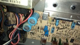
From the bottom of the PCB all solder joints seemed OK, no visible cracks and/or cold solder joints (Mexicans did a great job while assembling it). From the top i noticed that the transparent cover of the input jack socket was missing. After checking the others i realized that this cover is just for the dust, i think it has no other functionality.
I also used my Ohm meter to check both jack sockets and i learned this way why it has 4 pins for mono signal: the 2 extra pins are for connecting signal to ground when jack is removed from socket, like an auto switch. Also by this test i realized that the input jack socket works electrically as intended. While doing all the previous tinkering, i noticed that the pin inside the input jack socket that contacts to the tip of the jack (signal) is broken and has no contact with the jack. It had a little more of the pin left, so i just bent it upwards and it makes good contact with the tip when the jack is inserted. I double checked that it has continuity as intended and no short circuit when jack is plugged and unplugged, i temporarily connected the speaker and power cord, i wore my earplugs, sent my dog to the bottom floor and fired up the "beast". Everything is fixed! The amp works again like a charm! 
Reassembled it and i am amazed by the sound and db this small amp produces. Both with closed back (factory) and open back, it produces great clean and OD tones for practicing in my room.
I am sure it will be able push a fair amount of air, when i add an adequate 1X12" 8Ohm speaker cabinet. (i plan to create a new thread when i finish building the cab and converting the combo amp to an amp head)
So now i have four options:
i) Leave it as it is right now, until jack socket dies again and then replace it.
ii) Replace with the original Fender jack socket for PCB, that costs 7.5 euros local price (about 8.5$ atm).
iii) Replace with a generic metal jack socket with nut (like the one electric guitars have, cost from 2$ i may have one in my spare parts box) using some short wires from the PCB to the socket pins and,
iii.a) leave the two switching pins always disconnected (input always on: it may produce the same noise if the guitar cable gets unplugged from amp while on volume other than zero)
iii.b) add a microswitch to manually turn input on-off.
iv) Replace with a 4 pin mono jack socket, like those that some electroacoustics with EQ-compressor and piezoelectric pickup have, in order to switch off the 9V battery. I don't know how easy it will be to find one or how much it costs, i suppose from 3-4 euros.
What do you say? I think the best route is to enjoy it like it is now and replace with the original part when it dies again. Notice that the cost of this small part, is almost 1/5 of the used market price of this amp.
I loved the quality and simplicity of the construction and hardware.
The Fender logo on the front grill is made out of metal (sweet)!!! Even if this amp goes to garbage some day, the metallic Fender logo will stay here.
Next step, modding the PCB:
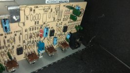
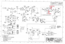
If you examine closely the last three photos, you can see clearly that there is a reverb circuit printed on the PCB but has no components on.
Is it possible to find or calculate the characteristics of the components of the reverb circuit? Is there any other similar reverb circuit available online?
Do you have any schematics or guidelines to share?
Google did not help me till now. I suppose the Frontman R is the reverb version of the amp, maybe like Frontman 15R.
Also i would like to add an FX loop (send-receive) but i have no clue. Is that possible and how? Even if i don't add the reverb components on the PCB, FX loop capability gives me the opportunity to use whatever modulation pedal i like.
Does anyone know any DIY spring reverb pedal circuit, worth building?
Any other recommendation or ideas for modding the amp is welcome. Like any kind of EQ boost or tone-sound setting i could add. Even a tube preamp for making it a hybrid amp. Or some good and cheap circuit for converting it to full tube. Or finally whatever kind of small components (resistors, capacitors, etc) i could add and use as switchable effects with on-off switches, dip switches, etc.
Adding some foot-switch jack connections will be the easy part, if i need to foot switch the OD or the reverb in the future.
Thanks everyone,
Panos
(after you open the photos they look OK, some thumbnails look a little stretched)


I was very lucky, easiest fix ever!
I now need info and ideas for modding the PCB to add FX loop and/or a reverb circuit (read after the fixing procedure).
How it was fixed: After your ideas i started disassembling the actual amp board from the cab.
From the bottom of the PCB all solder joints seemed OK, no visible cracks and/or cold solder joints (Mexicans did a great job while assembling it). From the top i noticed that the transparent cover of the input jack socket was missing. After checking the others i realized that this cover is just for the dust, i think it has no other functionality.
I also used my Ohm meter to check both jack sockets and i learned this way why it has 4 pins for mono signal: the 2 extra pins are for connecting signal to ground when jack is removed from socket, like an auto switch.
Also by this test i realized that the input jack socket works electrically as intended. While doing all the previous tinkering, i noticed that the pin inside the input jack socket that contacts to the tip of the jack (signal) is broken and has no contact with the jack. It had a little more of the pin left, so i just bent it upwards and it makes good contact with the tip when the jack is inserted. I double checked that it has continuity as intended and no short circuit when jack is plugged and unplugged, i temporarily connected the speaker and power cord, i wore my earplugs, sent my dog to the bottom floor and fired up the "beast". Everything is fixed! The amp works again like a charm! Reassembled it and i am amazed by the sound and db this small amp produces. Both with closed back (factory) and open back, it produces great clean and OD tones for practicing in my room.
I am sure it will be able push a fair amount of air, when i add an adequate 1X12" 8Ohm speaker cabinet. (i plan to create a new thread when i finish building the cab and converting the combo amp to an amp head
)So now i have four options:
i) Leave it as it is right now, until jack socket dies again and then replace it.
ii) Replace with the original Fender jack socket for PCB, that costs 7.5 euros local price (about 8.5$ atm).
iii) Replace with a generic metal jack socket with nut (like the one electric guitars have, cost from 2$ i may have one in my spare parts box) using some short wires from the PCB to the socket pins and,
iii.a) leave the two switching pins always disconnected (input always on: it may produce the same noise if the guitar cable gets unplugged from amp while on volume other than zero)
iii.b) add a microswitch to manually turn input on-off.
iv) Replace with a 4 pin mono jack socket, like those that some electroacoustics with EQ-compressor and piezoelectric pickup have, in order to switch off the 9V battery. I don't know how easy it will be to find one or how much it costs, i suppose from 3-4 euros.
What do you say? I think the best route is to enjoy it like it is now and replace with the original part when it dies again. Notice that the cost of this small part, is almost 1/5 of the used market price of this amp
.I loved the quality and simplicity of the construction and hardware.
The Fender logo on the front grill is made out of metal (sweet)!!! Even if this amp goes to garbage some day, the metallic Fender logo will stay here.
Next step, modding the PCB:
If you examine closely the last three photos, you can see clearly that there is a reverb circuit printed on the PCB but has no components on.
Is it possible to find or calculate the characteristics of the components of the reverb circuit? Is there any other similar reverb circuit available online?
Do you have any schematics or guidelines to share?
Google did not help me till now. I suppose the Frontman R is the reverb version of the amp, maybe like Frontman 15R.
Also i would like to add an FX loop (send-receive) but i have no clue. Is that possible and how? Even if i don't add the reverb components on the PCB, FX loop capability gives me the opportunity to use whatever modulation pedal i like.
Does anyone know any DIY spring reverb pedal circuit, worth building?
Any other recommendation or ideas for modding the amp is welcome. Like any kind of EQ boost or tone-sound setting i could add. Even a tube preamp for making it a hybrid amp. Or some good and cheap circuit for converting it to full tube
. Or finally whatever kind of small components (resistors, capacitors, etc) i could add and use as switchable effects with on-off switches, dip switches, etc.Adding some foot-switch jack connections will be the easy part, if i need to foot switch the OD or the reverb in the future.
Thanks everyone,
Panos
(after you open the photos they look OK, some thumbnails look a little stretched)
I have seen your reply after posting my previous message
I have seen your reply after posting my previous message.
I solved the problem, it was the input jack socket. It had a broken contact point. Check my previous reply for details.
Thanks for the service manual! Looks like it is what i need for the reverb and schematics of the amp. On first sight it looks the same with my amp, but it is one product version newer.
If you have any clue for the other mods i ask in my previous message (FX loop, etc) please share your knowledge and/or thoughts.
Extra pins i meant. Check my last reply, i answered my question "why there are 4 pins on the PCB mount of the jacks socket for mono signal", using my Ohmmeter and logic. Briefly, in my amp they ground the signal input when the cable is disconnected from the amp.
All kinds of things can make all kinds of symptoms. I suggest following advice in order given as it is more likely than something esoteric.
The schematic I attached is REALLY close to your unit.
Extra pins on jacks? SOme may be unused, others are cutout contacts that do jobs like ground the tip when jack is empty. Others may be involved with muting circuits. All depends upon the amp.
I have seen your reply after posting my previous message.
I solved the problem, it was the input jack socket. It had a broken contact point. Check my previous reply for details.
Thanks for the service manual! Looks like it is what i need for the reverb and schematics of the amp. On first sight it looks the same with my amp, but it is one product version newer.
If you have any clue for the other mods i ask in my previous message (FX loop, etc) please share your knowledge and/or thoughts.
Extra pins i meant. Check my last reply, i answered my question "why there are 4 pins on the PCB mount of the jacks socket for mono signal", using my Ohmmeter and logic. Briefly, in my amp they ground the signal input when the cable is disconnected from the amp.
Congratulations!I was very lucky, easiest fix ever!

Thanks to Enzo providing that manual, adding reverb looks straightforward. All you need is one double op-amp, a few passive components, and the actual spring reverb unit (the only slightly tricky part!)
-Gnobuddy
> leave the two switching pins always disconnected (input always on: it may produce the same noise if the guitar cable gets unplugged
No. There is a standard Switchcraft jack with a shorting switch, which was used on ALL guitar amps until that plastic PCB style came into favor. The one you want has 3 wire-lugs but only one plug-finger. Under that finger is a short leaf which touches the plug finger when no plug is installed. Wire the short leaf to ground.
You can also use the "Marshall" style plastic jacks. These usually have a lug which touches the plug-finger when no plug is installed.
A amp which SCREAMS if unplugged is Dangerous. As you dog will tell you.
Congratulations!
Thanks to Enzo providing that manual, adding reverb looks straightforward. All you need is one double op-amp, a few passive components, and the actual spring reverb unit (the only slightly tricky part!)
-Gnobuddy
You all gave me great info and advice! Service manual is always priceless, like any kind of technical or safety info.
Again, thank you all!!!
The reverb circuit seems easy now. I have to check the components for availability and total cost, to consider if it is worth the money. Else i will just build a reverb pedal
.Still need to figure out where i could add FX loop (send-receive) in the amp circuit . I suppose it is easy and simple, but i am not totaly sure atm. I am trying to learn from other amp schematics that have FX loop sockets implemented from factory. Could you provide any FX loop circuit that would be OK for my PCB and purposes? Alternatevely a simply designed amp model that in your experience has a simple FX loop circuit, will also do the job after i locate and read it's schematics.
Last edited:
> leave the two switching pins always disconnected (input always on: it may produce the same noise if the guitar cable gets unplugged
No. There is a standard Switchcraft jack with a shorting switch, which was used on ALL guitar amps until that plastic PCB style came into favor. The one you want has 3 wire-lugs but only one plug-finger. Under that finger is a short leaf which touches the plug finger when no plug is installed. Wire the short leaf to ground.
You can also use the "Marshall" style plastic jacks. These usually have a lug which touches the plug-finger when no plug is installed.
A amp which SCREAMS if unplugged is Dangerous. As you dog will tell you.
You have spoken wisely.
Thanks! I don't want to risk my ears, or my dogs ears, my friends ears, etc. Marshall amps are sold everywhere here, but i have no clue for their parts.This "auto-switch" has a good reason of being.
When my temporary fix dies, i will spend the 7.5 euros for the original Fender part.
The Marshall part i suppose will be at the same price or even more. Fender part is plastic too. The only metallic on this is the nut-washer and the contacts.
Also i have easy access to Fender parts, but i am not sure who imports Marshall parts here.
Last edited:
If you are going to install the reverb circuit, then either ordering up a spare reverb tank from Fender is an option, also consider Mod/Ruby tanks. Either way it's a tank with high input impedance designed to be driven by op-amps, not the low impedance version which is usually for valve/transformer drivers.
The replacement tank for Fender 15R is going to be tiny, and I don't like the sound of them much. You could go for a medium size tank and mount in bottom of amplifier cabinet, if you want. The Blues Jr has op-amp driven reverb despite being a valve amp, and uses the medium size tank.
Electrically the size doesn't matter. The crappy little reverb in this amp is used for its size, it fits in the amp. The small pan in the BLues Junior fits in its cabinet. But if you have the room, a full size pan is fine. The circuits won't care.
4EB2C1B is typical of full size. 8EB2C1B for small pan.
4EB2C1B is typical of full size. 8EB2C1B for small pan.
I owned a 25R briefly. The reverb wasn't bad if you kept the level low....The 25R used the same tiny reverb...
But turn it up a bit, and it would make this bizarre hyperactive-metallic-woodpecker-sliding-down-the-inside-of-a-drainpipe noise. Pick a note on the guitar, hear the mad woodpecker.

-Gnobuddy
Yes it was passable at quite low levels, from what I remember.. but the mad woodpecker sound is a good description!I owned a 25R briefly. The reverb wasn't bad if you kept the level low.
In the next month i will have an appropriate 1X12 inch cabinet to connect.
The 8inch speaker will be removed and i am planning to cut the amp combo in half so it looks like an amp head. So no problem to fit a bigger than factory spring reverb in there.
BUT the only problem i see is the cost. I can find even bigger/better amp combos with spring reverb for like 50-80 euro used (like Randal RG80 for 80 euros, Dean Markley K65 for 80, Ibanez 50 for 60euro, Fender Rock pro 1000 combo for 100euro, etc). An aftermarket reverb tank costs like 30-40 euros plus shipping/fees. A Frontman R costs like 50 euros max, used. I suppose that Fender will not sell for less than 30-50 euros their reverb tank as a part (Monday i will know).
What i am trying to say: i see that it is possible to add reverb on my amp, but does not worth the money, cause sping tank is not cheap and i have better alternatives.
Also i already have a GFX-5 guitar effects processor and some pedal effects including Digitech polara and Boss reverb, so the most value for money is to add an FX loop on my Frontman amp to make good use of my effects gear.
In the end it is much better to build my custom spring reverb external module/pedal and use it in FX loop anywhere i like, full of pride .
.
So coming back to the question: is it possible to add a proper FX loop on my amp? Is it possible to use the reverb circuit except of the reverb tank, using the reverb send and receive as FX loop send/receive? How many watts and what Ohms is my amps circuit rated to send and receive from the reverb tank? How do i calculate from Fender reverb circuit, how many Ohms it sends and how many is it supposed to receive? Is it possible with minor adjustments to the resistors or caps, to modify this and work as FX loop? Check my attached image to understand what i am talking about.
The 8inch speaker will be removed and i am planning to cut the amp combo in half so it looks like an amp head. So no problem to fit a bigger than factory spring reverb in there.
BUT the only problem i see is the cost. I can find even bigger/better amp combos with spring reverb for like 50-80 euro used (like Randal RG80 for 80 euros, Dean Markley K65 for 80, Ibanez 50 for 60euro, Fender Rock pro 1000 combo for 100euro, etc). An aftermarket reverb tank costs like 30-40 euros plus shipping/fees. A Frontman R costs like 50 euros max, used. I suppose that Fender will not sell for less than 30-50 euros their reverb tank as a part (Monday i will know).
What i am trying to say: i see that it is possible to add reverb on my amp, but does not worth the money, cause sping tank is not cheap and i have better alternatives.
Also i already have a GFX-5 guitar effects processor and some pedal effects including Digitech polara and Boss reverb, so the most value for money is to add an FX loop on my Frontman amp to make good use of my effects gear.
In the end it is much better to build my custom spring reverb external module/pedal and use it in FX loop anywhere i like, full of pride
.So coming back to the question: is it possible to add a proper FX loop on my amp? Is it possible to use the reverb circuit except of the reverb tank, using the reverb send and receive as FX loop send/receive? How many watts and what Ohms is my amps circuit rated to send and receive from the reverb tank? How do i calculate from Fender reverb circuit, how many Ohms it sends and how many is it supposed to receive? Is it possible with minor adjustments to the resistors or caps, to modify this and work as FX loop? Check my attached image to understand what i am talking about.
Attachments
Last edited:
- Status
- This old topic is closed. If you want to reopen this topic, contact a moderator using the "Report Post" button.
- Home
- Live Sound
- Instruments and Amps
- Fender PR 241 repair (Frontman amp made in Mexico, high pitch sound)