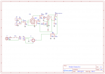
I have been trying to design a schematic based on the Fender Champ 5c1, with a few tweaks and updated some of the outdated design aspects. Among other things i wanted to switch from the original 5y3 rectifier tube to a SS bridge rectifier, but i am unsure of wether the way i did it is right or not. I have excluded a few bits of the schematic as they were irrelevant to the main circuit.
I'd appreciate some feedback on the rectifier, and maybe other potential flaws. Thank you.
Google Drive: Sign-in
I'd appreciate some feedback on the rectifier, and maybe other potential flaws. Thank you.
Google Drive: Sign-in


Agree^^^ Back when 5C1 was a current model, caps were not cheap, especially at voltage, so they used 8uf filter caps. These days 8uf is not a standard value, though you can pay largeg money for them on the nostalgia amp market. 10uf and 22uf are standard values. 10 uf would be indistinguishable from 8uf. I myself would use 22uf, but either way...
Not sure I would use a bridge rectifier and only use half. I would just use two diodes.
The 5C1 and 5E1 draw the power tube B+ from the second node, 5F1 and later draw it from the first (reservoir) node. So the 5C1 should be RELATIVELY less humy than the later ones. That is why most Champs and other SE amps are hummy, they use the first node which always has ripple.
The very first DIY amplifier I ever built was a 5C1 clone. This was in about 1964 and all the parts came from scrap radios and TV sets. I built it like the original from a hand traced schematic. It worked, but had one big problem which the genuine Fender also had.
The input tube uses grid leak bias, as was common in those days. It's not a big problem when you plug in the old Hagstrom with relatively wimpy single coil pickups, but slam that thing with a DIY Vox Tone Bender (a germanium pedal like a fuzz face) and you can create blocking distortion in the input stage.
I got the ham radio guy who traced his brother's Champ for me to explain cathode bias to me and draw out a schematic. Problem solved, amp rocked as good as any in 1964. I just wished it had reverb since surf music was king.....until those kids from Liverpool took over the radio.
Basically you replace the 5 meg resistor (R3) with something around 220K eliminate C1 (replace with a short) reduce one of the 75K resistors (R1 or R2) to a low value like 1K to make one of the inputs higher gain. Break the connection between the cathode of the 6SJ7 and ground and insert a resistor of around 2.2K with a cap across it. Something in the 1 to 4.7uF is good, adjust to tweak the sound once it's working. R4 is currently 2 meg, It will need to be a lower value, probably around 470K.
I made a similar amp recently with a 6AU6 miniature tube for the input stage and I spent several days with three pots, one for the new cathode resistor, one for the screen grid (R4) and one for the plate load (R5) and three guitars. These three parts and the cathode bypass cap determine the amps tone, and how it reacts to overload on the input (pedals), tweak to taste.
I also played around with a 6AU6 and a pot for the plate, cathode and screen. Also switched in and out caps on the cathode and the screen. You can twiddle them and fairly quickly find the sweet spot(s) in the response. I never really paid attention to the input pentode, oops, it is grid leak. Actually they can sound interesting as long as you don't send any dc into it (capacitor on the input is a must if you run pedals that might leak dc) but cathode bias gives you grater versatility. I gave an example in another forum of switching between cathode bias and grid leak, not hard to do.

You people are doing god's work out here  .
.
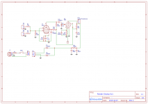
I have made a revised schematid based on a mix of all of your advice.
By the way, i was plannng to put all of the passive components on a PCB with wires going to the transformers and tubes, and then put the whole package in an adequately compact head, is this possible?
.I have made a revised schematid based on a mix of all of your advice.
By the way, i was plannng to put all of the passive components on a PCB with wires going to the transformers and tubes, and then put the whole package in an adequately compact head, is this possible?
Attachments
it is grid leak. Actually they can sound interesting as long as you don't send any dc into it
Driving it hard with a distortion pedal capable of nearly 9 volts peak to peak will turn that input tube's grid / cathode into a rectifier that generates a negative voltage. That will charge the input cap such that the grid can swing several volts negative when the input overload is gone. This cuts the input tube completely off until the cap's charge bleeds off, which can be a long time with a 5 meg resistor. The amp worked almost OK as long as I kept my cheapie voltmeter (maybe 100K ohm input) wired into the amp from grid to ground.
A dumm blonde 12 year old kid could not figure this out, hence my trip back to see my friend's older brother, the ham radio guy.
For some unique distortion effects, plug a 6SK7 into the input socket. It is a remote cutoff pentode which puts up with pedals a bit better.
R3 should be 1 mega ohm. Guitars don't like feeding into a lower load than that (you'll lose treble, i.e. experience the dreaded "tone sucking" that you read about on the 'Web, particularly with humbucker-equipped guitars.)...revised schematic...
R4,R5,R6 are inter-dependent. Using semi-random values for R4, R5, R6 can prevent the 6SJ7 stage from working at all. I think your 6SJ7 screen grid resistor is considerably too big. I've never used this exact tube, but similar ones I've tried required around 330k - 470k for the screen grid resistor.
George and Printer2 both recommend using pots for all three and tweaking to taste; if you don't want to take the time and trouble to do that, at least tweak R4 (screen resistor) by trial and error until you have 1.5V - 2V DC across R6 (cathode resistor.) This will give you a starting point, an operating point that will at least work, even if it's not exactly to your taste.
It's certainly possible - and frequently done, for example, in my old Fender Blues Junior....put all of the passive components on a PCB with wires going to the transformers and tubes, and then put the whole package in an adequately compact head, is this possible?
Make sure to keep wire lengths - especially to tube grids and anodes - as short as possible. Not only do these wires pick up noise and interference, they can also cause the amp to become an oscillator, either squealing audibly, or oscillating at radio frequencies, much higher than we can hear.
Personally, if I was going to the trouble of making my own PCB, I would put the tubes on the PCB as well. Just reinforce the top surface of the PCB, where each tube socket goes, with an appropriately sized square of thin aircraft plywood (available at hobby shops and craft shops) epoxied to the PCB itself, and then drill your PCB holes through both plywood and PCB substrate.
This approach will shorten the "wires" (PCB traces) from passive components to tube pins a great deal, and this usually pays rewards in improved amp stability and reduced noise and interference pickup. The plywood reinforcement keeps the PCB from flexing too much and becoming damage when you insert or remove a tube.
-Gnobuddy
...updated some of the outdated design aspects....
You draw the heater with one side grounded. That was marginally acceptable in 1952. It is better to spend the extra wire and run the heaters center-tapped around ground.
The grid-leak bias is a matter of taste; and what guitars are used. As TL says, it worked in the old days, but can be fussy with today's hotter pickups and with effects. For grid-leak you want an input cap and a >1Meg grid resistor so leakage builds up good grid bias. The alternate is to add a 1k + 22u cathode bias network and use the conventional Fender 1Meg input found on all later amps.
With sillystate diodes you could raise the first filter cap off the rectifier to 50uFd or more, less hum. The 500r dropper is essential to low hum (do not be afraid to raise it to 1k-- less hum for only small change of power). The next (OT) 8-10uFd cap *may* affect tone in overdrive; I'd lean to staying in the original range. Or play it a week with 10u and a week with 100u, see what difference it makes to you.
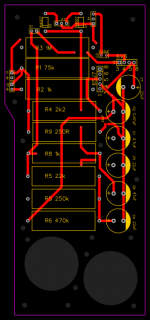
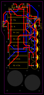
Thank you all so much! I have again made multiple revisions, this time however i have made a PCB, with pads which will take wires from the pcb into the tubes, which are to be mounted on the board, but not with TH sockets, rather by Gnobuddy's suggestion.
I'm planning on using 5w carbon film resistors as well as radial electrolytic caps rated at 400v for the circuit, will these work fine?
I'm planning on using 5w carbon film resistors as well as radial electrolytic caps rated at 400v for the circuit, will these work fine?
Attachments
I think 1/2 watt resistors will be fine everywhere except for R7 & R9, which will need bigger power ratings.I'm planning on using 5w carbon film resistors as well as radial electrolytic caps rated at 400v for the circuit, will these work fine?
Is R7 really only 250 ohms? The 5F1 schematic I looked up uses 470 ohms. And online discussion suggests that even 470 ohms is too small, a design mistake on Fender's part; Leo raised the B+ voltage for more output power, but forgot to increase the cathode resistor at the same time.
I see 1k recommended for the Champ cathode resistor, to keep power dissipation in the 6V6 within its design ratings. For instance, post #8 by John Phillips here: More on 6V6 bias: Fender Champ | The Gear Page
If you know the designed DC cathode voltage (control grid bias voltage) of the 6V6, that lets you figure out what the power rating of R7 will be. Double or triple that for a nice big safety margin. Or find out what other people use, and use that. The Champ is an ancient design, no need to re-invent the wheel.
For R9, I note that the 6V6 datasheet shows anode currents up to 110 mA (at Vgk=0), and that's with only 250V on the screen grid; the Champ seems to put much higher voltage on the screen, so it's probably safe to assume up to 150 mA peak anode currents, worst case.
So you have a 500 ohm resistor (R9) with peak currents of 150 mA, and an average current roughly half that; 75 mA and 500 ohms compute to nearly 3 watts power dissipation.
I think a 5W resistor here will run quite hot, so my suggestion is to use a 10 W resistor for R9 instead. It's a bit overkill, but I've never regretted using a slightly too-big power rating. (I can't say the same for using a slightly too-small power rating!)
Incidentally, 470 ohms is the standard value, not 500 ohms. It won't make a difference electrically, but you may find it easier to source a 470 ohm, 10 W resistor than a 500 ohm, 10 W resistor.
-Gnobuddy
- Status
- This old topic is closed. If you want to reopen this topic, contact a moderator using the "Report Post" button.
- Home
- Live Sound
- Instruments and Amps
- DIY 5c1 style amp