I agree!...headers...are definitely confusing...
This is too confusing to be even the least little bit usable. It invites errors, and lots of them. Trying to draw a correct schematic in which every component is shown as a rectangle is a bit like trying to correct the spelling of the rest of this sentence, which I shall write using only the letter "a" to replace all aaa aaaaa aaaaaaa aa aaa aaaaaaaa.

See the attached image for yet another bit of confusion - what happened to the value of the 6V6's screen grid resistor?
-Gnobuddy
Attachments
The thing that's being overlooked is the screen grid voltage on the 6V6, which also factors into the proper value of cathode resistor.1k for the cathode on the 6V6? Seems a little high.
The 5C1 seems to use a very large 25k dropper resistor to feed the screen grid (and the preamp pentode). The screen grid must be at a relatively low DC voltage as a result. And Leo used a 470 ohm cathode resistor.
The 5F1 uses a 10k dropper resistor between B+ and the screen grid node of the power supply, less than half as big as the 5C1's 25k. It seems power transformer voltage was raised too. So there's going to be lots more DC voltage on the screen grid. As a result, some people found it took a 1K cathode resistor to bring plate dissipation within the 6V6's specifications - I linked to a thread about this earlier.
Me, I take the conservative engineering approach. I would rather start with the 1k cathode resistor, measure DC voltages, calculate plate dissipation, and only lower the 1k if the 6V6 was safely within specs and still had a safe margin for further abuse.
-Gnobuddy
For a beginner, it is much safer to start with a solid-state guitar amp or FX pedal. There are very simple solid-state guitar amp designs out there too, such as the Ruby amp.
[...]
If it must be a tube amp (more on this later), I encourage you to work from
[...]
Why not download and read some of the many free introductory electronics books on the 'Web?
There are several nice free books at this link: Lessons In Electric Circuits
There are many DIY guitar pedal kits here: DIY Guitar Effects Pedal and Amplifier Kits – Build Your Own Clone
Lots of DIY guitar pedal schematics and builds here: freestompboxes.org • Index page
-Gnobuddy
Thank you sir!! You are a Sensei (a.k.a. the one that already knows=teacher/professor).
This is what i need, more resources to read. Good info for the wattage of resistors, this is what i was asking for(not amperage). Thankfully i know electromagnetism through my scientific field, just needed a "push" to practically apply some basic laws on electronics too. Thanks!
I have already built the Ruby amp, used it as a pedal effect too.
I am planning to build some effect pedals, also maybe a tube preamp/overdrive pedal too.
But for the amp, yeah, it has to be a tube amp
. I feel it doesn't worth to build a transistor amp for my guitar. Giving all this effort i would like to end with a full tube(valve) guitar head . Good transistor amps are dirt cheap when used, and most of the time they are not something special, so no reason to build one. On the other hand, tubes sound great when playing the guitar.Among others, i have read the Rob Robinette's page, i will do it again.
I will certainly follow your suggestions and start from a better 5E1 (5F1) amp design.
In general, i prefer amp designs with FX loop capability. Is there any other (simple) amp model design you would suggest, that has FX loop? Preferably a tube driven FX loop, if it needs to be amplified or impedance matched.
Last edited:
I understand. Most transistor guitar amps sound horrible, and most have sounded horrible since the 1960s, for over fifty years now!I feel it doesn't worth to build a transistor amp for my guitar.
(But very recently there are starting to be a few noticeable exceptions: listen to this solid-state amp: YouTube )
I agree about the "not something special", at least 99.9% of the time. But the reason to build one is to gain experience with electronics, while keeping you alive!Good transistor amps are dirt cheap when used, and most of the time they are not something special, so no reason to build one.
Seriously, it scares the heck out of me to think about newcomers to electronics starting to work with circuits that have 350 volts or more inside them. These are potentially lethal voltages.
Not all, in my opinion. I have heard tube amps that sound like "nothing special" too. Years ago I bought a VOX AC4TV, hated the boxy sound, returned it. I also bought a Blues Junior, hated the boxy sound and "growly" tone, and sold it on Craigslist.On the other hand, tube sounds great when playing the guitar.
The thing is, an FX loop by itself is about as complicated as an entire Champ - it may actually use more components!Is there any other (simple) amp model design you would suggest, that has FX loop? Preferably a tube driven FX loop, if it needs to be amplified or impedance matched.
For example, a 5F1 Champ has one 12AX7 tube in it, and just a few resistors and caps in the preamp, and one pot. To add an FX loop, you would need one more 12AX7 tube, one more tube socket, extra heater power, several more caps and resistors, one send-level pot, one return-level / recovery gain pot, a 1/4" jack for the "Send" signal, another one for the "Return" signal, and maybe a few other things I forgot. Suddenly the circuit will be at least twice as complicated.
So "simple tube amp" and "FX loop" pretty much do not go together. That's why you don't see any schematics for these.
Personally, I think "tube driven FX loop" makes no sense whatsoever; today, a guitar FX loop is an ideal application for modern high-voltage MOSFETs, not tubes. But that is an entirely different discusion.
-Gnobuddy
Indeed today exist modelling amps that are really good on what they offer. But they are 100% digital... and they are still starting... No comparison though with a JCM 800 or any good tube amp from Orange, Fender, Mesa Boogie, Hughes Kettner, VOX, ENGL, etc Till now, all good tube amps are far better sounding than modelling amps. Imo in the future this may change and digital modelling will get much better.I understand. Most transistor guitar amps sound horrible, and most have sounded horrible since the 1960s, for over fifty years now!
(But very recently there are starting to be a few noticeable exceptions: listen to this solid-state amp: YouTube )
-Gnobuddy
Good point, but still makes some sense to have FX loop on tube amps, when you need i.e. reverb and do not want to implement it straight in the main amp circuit. I use reverb most of the time.The thing is, an FX loop by itself is about as complicated as an entire Champ - it may actually use more components!
[...]
So "simple tube amp" and "FX loop" pretty much do not go together. That's why you don't see any schematics for these.
Personally, I think "tube driven FX loop" makes no sense whatsoever; today, a guitar FX loop is an ideal application for modern high-voltage MOSFETs, not tubes. But that is an entirely different discusion.
-Gnobuddy
Maybe Bugera, tonecity or Marshall tube products that have reverb and FX loop could serve my purposes, and also build my own without FX loop, and call it minimalistic vintage amp
.Don't get scared with me and electricity, i am the kind of guy that tinkers even my houses 220Volt lines, repairs fridges, microwave ovens, etc. I believe i can build a tube amp and remain aliveI agree about the "not something special", at least 99.9% of the time. But the reason to build one is to gain experience with electronics, while keeping you alive!
Seriously, it scares the heck out of me to think about newcomers to electronics starting to work with circuits that have 350 volts or more inside them. These are potentially lethal voltages.
-Gnobuddy
Last edited:
1k for the cathode on the 6V6? Seems a little high.
I wanted to use one with the same resistance and power rating as another on the board, since i'm ordering everything in multiples of atleast 5 it would have been most efficient, however these parts are cheap as chips so thats not a problem, how about 470 ohm?
Also, would it be possible to take my existing design and replace the preamp section with the 12ax7 based one from the 5E1 Champ instead? those tubes are a bit more readily available and apparently work better with modern guitars from what i can gather.
At the time that I was building Champ clones (mid 60's) there were no schematics available, and 12AX7's were not yet common in the trash. Sometime later, maybe late 60's a high school friend traced out the circuit of his 5F1 which used a 12AX7.
I built one, again with parts sourced from the trash. I liked it better than the 5C1 clone, so started making them.....It was about the time that you could find some scrap Magnavox HiFi sets with a 12AX7 and a 6V6 in the trash dump.
Fast forward to the late 90's. My daughter was in the high school marching band. Most of her friends carried musical weapons of some sort, often a guitar. My daughter had a full double bass drum cage, so our rec room was the designated practice spot. I made them a guitar amp.....then another, then several. All based on the Fender 5F1 Champ. No two were the same, and some of them used car stereo speakers obtained real cheap when the local K-mart closed down.
Most were hastily built from whatever I had around. Output tubes ranged from 6V6's and 6K6's to KT88's with several different transformer sets, most salvaged from amps that I had dissected. Many of the power transformers came from some scrap HP audio oscillators, some had tube rectifiers, some solid state due to the lack of a 5 V winding on the HP transformers. Most were given away for free, so cost was the driving factor, but they were good sounding amps. Some were upgraded, or built with real guitar speakers at the new owner's request. They bought the speaker.
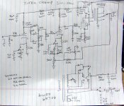
After the last amp was built I drew up this schematic from memory. it probably doesn't exactly match any of the amps since all were different, and no two were the same. All had some switches to affect the tone, some had tone stacks, some didn't. The number of switches and controls varied depending on what I was using for a chassis, how many holes I could get in it, and what switches and pots I had in my box of dead circuits.
At least two or three did use the 6K7VG power transformer, a KT88 and a Hammond 125 series OPT. That transformer produces about 430 volts of B+ which is far too much for a 6V6 or 6K6 tube. Those amps got the HP transformer for about 350 volts, or a 6K56VG transformer for about 335 volts.
I built one, again with parts sourced from the trash. I liked it better than the 5C1 clone, so started making them.....It was about the time that you could find some scrap Magnavox HiFi sets with a 12AX7 and a 6V6 in the trash dump.
Fast forward to the late 90's. My daughter was in the high school marching band. Most of her friends carried musical weapons of some sort, often a guitar. My daughter had a full double bass drum cage, so our rec room was the designated practice spot. I made them a guitar amp.....then another, then several. All based on the Fender 5F1 Champ. No two were the same, and some of them used car stereo speakers obtained real cheap when the local K-mart closed down.
Most were hastily built from whatever I had around. Output tubes ranged from 6V6's and 6K6's to KT88's with several different transformer sets, most salvaged from amps that I had dissected. Many of the power transformers came from some scrap HP audio oscillators, some had tube rectifiers, some solid state due to the lack of a 5 V winding on the HP transformers. Most were given away for free, so cost was the driving factor, but they were good sounding amps. Some were upgraded, or built with real guitar speakers at the new owner's request. They bought the speaker.
After the last amp was built I drew up this schematic from memory. it probably doesn't exactly match any of the amps since all were different, and no two were the same. All had some switches to affect the tone, some had tone stacks, some didn't. The number of switches and controls varied depending on what I was using for a chassis, how many holes I could get in it, and what switches and pots I had in my box of dead circuits.
At least two or three did use the 6K7VG power transformer, a KT88 and a Hammond 125 series OPT. That transformer produces about 430 volts of B+ which is far too much for a 6V6 or 6K6 tube. Those amps got the HP transformer for about 350 volts, or a 6K56VG transformer for about 335 volts.
Attachments
The thing that's being overlooked is the screen grid voltage on the 6V6, which also factors into the proper value of cathode resistor.
The 5C1 seems to use a very large 25k dropper resistor to feed the screen grid (and the preamp pentode). The screen grid must be at a relatively low DC voltage as a result. And Leo used a 470 ohm cathode resistor.
The 5F1 uses a 10k dropper resistor between B+ and the screen grid node of the power supply, less than half as big as the 5C1's 25k. It seems power transformer voltage was raised too. So there's going to be lots more DC voltage on the screen grid. As a result, some people found it took a 1K cathode resistor to bring plate dissipation within the 6V6's specifications - I linked to a thread about this earlier.
Me, I take the conservative engineering approach. I would rather start with the 1k cathode resistor, measure DC voltages, calculate plate dissipation, and only lower the 1k if the 6V6 was safely within specs and still had a safe margin for further abuse.
-Gnobuddy
The 290WEX, 239VAC@50mA? With no losses (x 1.414) you get 335Vdc. A little shy of the 350V in the above schematic. Even at 50mA across 470 ohms is there need for a 10W cathode resistor in an amp that puts out 5W? 23V across the resistor, multiplied by 50mA, 1.2W. Again, with no losses which is not realistic.
Given the transformer being used a 470R 5W would seem more appropriate. But then again, I am not a great authority on Champs. But these guys are, current production.
https://www.thetubestore.com/lib/thetubestore/schematics/Fender/Fender-57-Champ-Schematic-Rev-B.pdf
Effects loop can fit on a pef board, no heater current required. Put it after the volume control and before the second stage.
Last edited:
I built one, again with parts sourced from the trash.
All based on the Fender 5F1 Champ. No two were the same, and some of them used car speakers
This post really hit a nerve!!! 5C1 was my first Champ,, it uses a 10R Delco car speaker,, cause I had a NOS Merritt OPT with a 10R output,,, sounds amazing, much bigger sound than its small size... The last 5F1 I built turned into a 5F2A Princeton, to mess with the tone control... The latest is a 5F1 with 12 volt tubes, to use a PT with a 12V heater winding,,, and a 5V4 to get about 20-25 more B+ volts out of it...
Totally agree no two are exactly the same!!!!
Have fun with them!
The 6V6 tube in the Fender Champ, and many other Fender amps is run far beyond it's plate voltage spec of 315 volts. The screen voltage spec for the 6V6 at the time the original Champ was designed was 285 volts. Also exceeded in many amps. Some modern 6V6 tubes can eat a lot more voltage than the vintage stuff.
The large 10 to 25K dropping resistor prevented tube meltdown when the amp was driven hard into clipping because the screen voltage would drop when it started drawing heavy current. This also pulled the preamp's B+ voltage down, reducing it's gain and performing a self limiting function that prevented blown tubes. It is also a built in compressor of sorts with it's gain and time constants determined by the large resistor and the filter cap values.
This is what gives those old amps that punchy attach and long sustaining sound when driven hard. The small OPT and speaker had poor low frequency response which helps to reduce hum. That's why these amps often exhibit a faint hum when wired to a cabinet with bigger speakers.
I'm going by the part numbers in the linked TubeStore schematic since it's the most clear, and correct schematic. If one were to DIY a Fender Champ clone, it's a good schematic to use.
The resistors and cap values in the power supply filter R13, R14, C5, C6, and C7 will affect the B+ voltage, and how much of this "compressor" effect, and it's attack and recovery time you will get. Larger caps and smaller resistors will reduce the effect, but increase the B+ voltage, so the output tube's cathode resistor must be increased.
Diodes D1 and D2 and thermistor RT1 are added to prevent blown rectifier tubes and will not affect the sound. I added them to my SSE HiFi amp design to reduce dead rectifiers. A 5AR4 tube can be used instead of the 5Y3, it will produce more B+ voltage and better voltage regulation for a "tighter" sound.
R12 is the feedback resistor. It is a big contributor to the "tone" of the amp, and it's action is highly dependent on the speaker being used. Another place to tweak the tone.
C2 and C3 are the coupling caps. A higher value .047 or so will allow more bass through the amp, this can make it "fuller" or more muddy, this depends on your guitar, speaker, output transformer, and playing style. Adjust to taste, and they do not need to be the same value.
I see no reason for fuse F2, but someone must have found one.....I would leave it out, but that's just me.
So 18.5V across the 470R resistor, 0.0439mA. The GE datasheet says at 315V, -13V bias and 0.036mA, so not too far off of Fender's take. Seems the newer Champ's run the same voltages as the 360V (350V plate) in the Harvard schematic. They did increase the cathode resistor from 1W to 2W though, also added a 470R on the screen. So say 350-20 = 330V, multiplied by 0.040, 13.2W. So if we have 12W on the plate and 1.2W on the screen it would seem that the Champ is operating within its limits with Fender's values.
Using LND150s instead of tubes makes total sense, but the 3.2 HzEffects loop can fit on a pef board, no heater current required. Put it after the volume control and before the second stage.

input high-pass filter doesn't, nor does the unreliable biasing method (self-bias) for the recovery MOSFET. It only takes two more components to turn this into a reliable biasing scheme. Add one resistor to bias the gate of the 2nd MOSFET with a potential divider, like the first, but chosen to put something like 20V DC on the gate. Increase the source resistor accordingly. And add the second component - a small resistor in series with the source bypass cap - to define the AC gain.
-Gnobuddy
it would seem that the Champ is operating within its limits with Fender's values.
I have seen old Fender Champs that measure near 400 volts of B+ when plugged into the 122 volt outlet in Florida. Others have reported 380+ volts.
I haven't seen one here, but my wall outlet is around 125 to 126 volts on days with minimal electrical load. It drops to around 122 to 124 during the coldest days of winter.
The dissipation may be right at the edge of spec, and the B+ can be at or over spec, but even the old 6V6GT tubes seem OK with it. They live as long or longer than the 6L6GC's in a Bandmaster.
The official Fender schematic for my '65 Princeton Reverb reissue shows 440 volts on the 6V6 anodes.I have seen old Fender Champs that measure near 400 volts of B+ when plugged into the 122 volt outlet in Florida.
Probably not coincidentally, my second-hand PRRI came with big and beefy JJ 6V6S output valves in it.
I don't know what military-era Soviet tube this started out as, before JJ re-labelled it and changed the pin-out, but the JJ 6V6S appears internally identical to the JJ 7591. And IMO, doesn't look or sound much like current production "real" 6V6s that try to be closer to authentic.
-Gnobuddy
Using LND150s...sense... does the unreliable biasing method (self-bias) for the recovery MOSFET. ...
It makes sense. The LND150, unlike almost any other device we can name, is tightly specified for Id vs Rs, see page 5:
http://ww1.microchip.com/downloads/...etion-Mode-DMOS-FETs-Data-Sheet-20005454A.pdf
Also the output is a "small" signal (relative to supply voltage) so we don't need precision of operating point.
K.I.S.S.
I think you are misinterpreting that datasheet.The LND150, unlike almost any other device we can name, is tightly specified for Id vs Rs, see page 5:
The datasheet shows that Id vs Rs for one specific LND150 shows little variation with temperature (image attached.) There is no variation shown with Rs because the data is for one (bogey) FET.
I know that data is only for one single FE, because elsewhere on the same datasheet we see that Idss and Vgs(off) each vary over a huge 3:1 ratio (image attached.)
Just like ye olde JFETs of ancient times, apparently. Evidently the rumours of tighter tolerances in MOSFET parameters don't apply to the LND150.
300% variations in Idss and Vgs(off) automatically mean there will be large variations in drain current (Id) between different samples of the LND150, all with the same value of external source resistance.
Along with that will come large variations in headroom and voltage gain as well.
Isn't this exactly what good electronics design is supposed to eliminate? Large amounts of random variation between production samples?
As mentioned earlier, it doesn't take much additional complexity to do much better: just two additional resistors.
-Gnobuddy
Attachments
I don't understand why I can no longer see the schematic, I copied the link and pasted it in my browser and it opens.
https://music-electronics-forum.com/attachment.php?attachmentid=36235&d=1445867855
I'm not married to the circuit, fix bias the second stage, I don't mind. I just did not have time to go through a lot of pages to find the ideal circuit just to find it is discarded. I just wanted to show that you did not have to use tubes, sticking it after the volume control does reduce the need for another volume control on the send. On the return I would hope the effect jumpered in has a volume control on its output. You could still get some triode clipping of the first stage before sending it out the loop. I am sure it can be tweaked a little more in terms of parts count and simplicity, smart enough people on the forum.
- Status
- This old topic is closed. If you want to reopen this topic, contact a moderator using the "Report Post" button.
- Home
- Live Sound
- Instruments and Amps
- DIY 5c1 style amp