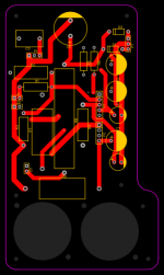
Cool! i beefed up the resistors and tweaked a bit more, all in all, what i'm most paranoid about is wether all the connections are right, but since im buying PCBs from JLCPCB and NOS russian tubes i wont be out much if that part gets messed up, but does it all look right? Thanks again for all the help 

78 cents for the 5W 470 ohm at Digikey.com ( https://www.digikey.com/product-det...nents/AC05000004700JAC00/PPC5W470CT-ND/596731 ); 85 cents for the 10 W, 470 ohm ( https://www.digikey.com/product-detail/en/yageo/SQP10AJB-470R/470W-10-ND/18774 ). Not much of a price difference for cooler operation and a nice safety margin.
I agree about keeping electrolytic capacitors cool. I have a pair of powered speakers that die every few years, because one of the power supply electrolytic caps is mounted right next to a hot power resistor, which slowly cooks it to death.
-Gnobuddy
I agree about keeping electrolytic capacitors cool. I have a pair of powered speakers that die every few years, because one of the power supply electrolytic caps is mounted right next to a hot power resistor, which slowly cooks it to death.
-Gnobuddy
I can read a simple schematic in a flash, but reading a PCB is tedious and slow. So I'm assuming the connections are correct.does it all look right?
You have lots of room to use fat copper traces, if you want. They don't have to be skinny. Wide traces will be more robust, and less copper needs to be etched away.
At first glance, the two tubes look very close together. Remember, they have to be able to radiate heat away from themselves, and you don't want any unwanted stray capacitance between the two tubes to cause the amp to oscillate and squeal. I suggest an inch or two of space between the two tubes.
I tend to do my physical layouts so they are not terribly different from the schematic itself. Signals enter at one end of the board, and leave at the other; ground is along one edge of the board, B+ along the other; passive components are mounted as close as possible to the tube or transistor they're connected to.
This tends to make the actual PCB traces or wires short and simple. But the component side of the board doesn't look like a tightly planned McHousing complex, with rows of identical components identically spaced in straight lines.
You've taken a very different approach, more typical of turret-board layouts in old Fender amps. All the resistors and caps are laid out in neat rows, but the wiring between them gets messy (lots of plated-through-hole vias and so on.)
I don't think either approach is wrong - both can get you to a working circuit. It's just a matter of preference, and which aspects matter most to you.
For me, short traces, minimal unwanted stray cross-capacitances, a logical signal and power flow, and most of all, good electrical performance matter most. For many hobbyists, the superficial appearance and neatness of of the layout matters most, and everything else is secondary (or not even a consideration.)
-Gnobuddy
At this point i have tweaked pretty much everything, i have moved the components around in order to keep traces shorter and i have updated the power ratings on most of the resistor, most notably the huge 10w R8 laying across the middle of the board, further away from all of the caps. i would like to keep the tubes where they are however, since if i were to move them apart i would likely have to redo most of the layout, or make the whole board into some awkward shape. In regard to the tubes i am not very worried about heat, but as far as that capacitance goes, would some form of shielding aid against that?
In terms of transformers i was thinking about a 290WEX for power and a 1750A for output, both from Hammond.
In terms of transformers i was thinking about a 290WEX for power and a 1750A for output, both from Hammond.
Attachments
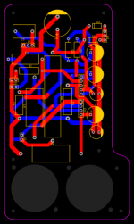
That looks much cleaner. Nice!I have moved the components around in order to keep traces shorter

27k is the standard value in the E12 resistor series now, and has been for many decades. 25k was presumably available in the early 1950s when the 5C1 was designed. That was a long time ago now - some sixty-five years!... huge 10w R8 laying across the middle of the board
This applies to most of the other resistors, too. 4.7M is standard, 5M is not; 2.2M and 1.8M are standard, 2M is not; 220k is standard, 250k is not.
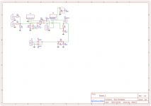
I'm still concerned about the value of R7, the 6V6 cathode resistor. The 5C1 schematic shows 500 ohms; you have 270, about half the proper value. And even the original 500 ohms apparently biases the 6V6 too hot, beyond its ratings.
Using a 270 ohm cathode resistor can make your 6V6 run very hot, so hot that it could be damaged.
I would suggest you replace R7 with at least a 470 ohm resistance to start (not 270). Once your circuit is up and running, you can measure the DC voltages and calculate power dissipation in the 6V6, to make sure it's not cooking itself to death. If it is, you can replace R7 with an even bigger resistor, as needed.
Is it an option to make the board a couple of inches longer, without changing anything else? Or are you locked into a certain maximum length dimension?...tubes...to move them apart...have to redo most of the layout...
I have no personal experience with cramming tubes this close together, so I can't tell you from personal experience how much this might affect the ability of the 6V6 to shed heat. It's the 6V6 I'm concerned about, as it's usually operated at the ragged edge of its ratings in a simple class A amp like this. The preamp tube is operating at relatively low power, and not near its maximum ratings, so it's not stressed as much.
Unwanted stray capacitive coupling between the two tubes is the easier part to deal with. Firstly, it may turn out not be an issue at all, in which case, great! But if it does become an issue, you may be able to insert a grounded sheet of metal (or blank copper-clad PCB board) vertically between the two tubes. (But this will give even less room for the tubes to radiate away heat.)
-Gnobuddy
The 290WEX, 239VAC@50mA? With no losses (x 1.414) you get 335Vdc. A little shy of the 350V in the above schematic. Even at 50mA across 470 ohms is there need for a 10W cathode resistor in an amp that puts out 5W? 23V across the resistor, multiplied by 50mA, 1.2W. Again, with no losses which is not realistic.
Well, Gnobuddy, i am unsure wether you looked through the newest schematic but i have now changed up most of the resisor values, including increasing R7 to 1kohm as well *** switching all of the resistor values to standard values, even going as far as researching each part individually, which was made very easy by the connection between easyeda and lcsc.com.
As far as any of the resistors being overkill, with any electronics i have worked with, heat has always been the biggest killer, hence the liberal use of 10, 5 and 3w resistors, which should hopefully keep avoidable heat to a minimum.
Also, i am unsure, but are cement resistors alright for this purpose? they are the easiest ones to get with these values and ratings, as well as keep the price of what is, essentially, a first experiment, as low as possible.
You guyz rock!
This will may be my first diy tube amp. I love how simple it is.
Excuse me for my noob/silly questions.
Which resistor/resistors need to be of more amperage? i.e. R7,R8 and R9 should be 10 Watts. The rest? Which could be 1/2, 3, 5 Watts?? I think Gnobuddy already partially answered on page 2, but i am lost. How do you plan to do it Alex1238?
Noob question No2: Alex1238, where is the volume/gain pot on the last schematic you uploaded? What Wattage should it be?
Noob question No3: What type of capacitors and of what voltage rating should all of the capacitors be? Are all of them the same type and max voltage rating?
Noob question No4: What type of transformers are needed?
Last edited:
Well i'm a complete noob as well but i will answer what i can. I'm still not completely sure regarding the wattage of the resistors myself. The pot is P1 on the schematic, i am planning to use a regular panel mount potentiometer which are typically rated to 1/2-1w, which should be enough. All of the capacitors i used are radial electrolytic caps except for C3 which is a CBB cap, all rated to 400v, although 350v rated ones should also work.
For transformers i have opted to go for the 290WEX for power and the 1750a for output, both from Hammond.
For transformers i have opted to go for the 290WEX for power and the 1750a for output, both from Hammond.
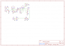
Please see the attached image. I took the newest schematic you posted, and indicated some of the problems I see....the newest schematic...
There are two sets of different pin numbers on the 6V6, making it hard to be sure what you intended, but the schematic still shows 270 ohms from one of the pins to ground. Logically, that should be the 6V6 cathode. This resistor is R9. It should not be 270 ohms.
They should be fine.are cement resistors alright for this purpose?
-Gnobuddy
Attachments
For a beginner, it is much safer to start with a solid-state guitar amp or FX pedal. There are very simple solid-state guitar amp designs out there too, such as the Ruby amp.This will may be my first diy tube amp. I love how simple it is.
Tube amps contain very dangerous high voltages. Not recommended for beginners.
If it must be a tube amp (more on this later), I encourage you to work from the unmodified Champ schematic. The one shown in this thread is a work in progress, untested, and it still contains errors.
Even with the errors corrected, this particular, very old Champ (5C1) has problems with modern guitars with powerful pickups, and/or effects pedals. Tubelab pointed these out early in this thread.
If you're looking for a first DIY tube amp, you might be better off with a later, improved Champ design. The 5E1, for instance, which uses a 12AX7 rather than the 6SJ7, and cathode bias rather than the problematic grid-leak bias which was abandoned long, long ago.
This page by Rob Robinette has a nice explanation of the 5E1 Champ circuit: How Amps Work
You mean wattage? This is calculated by using any one of three formulae. Power in a resistor = V * V/R, or I*I*R, or V*I. In each case, "V" is the DC voltage across the resistor, "R" is the resistance in ohms, and "I" is the current through the resistor in amperes.Which resistor/resistors need to be of more amperage?
If you find a Champ schematic with DC volts indicated on it, you can then fairly easily calculate the amount of power dissipated in each resistor.
Resistors get very hot if used at their full power rating. A "half watt" resistor gets extremely hot if you actually ask it to dissipate half a watt. So the next step is to add a nice safety margin to your calculation. If you calculate that a certain resistor will dissipate, say, 0.8 watts, I recommend doubling or tripling that to tell you what resistor wattage to buy. In this case, doubling 0.8 watts suggests a 1.6 W resistor (not available), and tripling it suggests a 2.4W resistor (also not available.) So I would use a 2 W resistor in that location.
What I described above is how you do it with a design that's new. But the Champ is an ancient design. So if you're not in the mood to calculate the power in each resistor, you don't need to. Simply look up the parts list / BOM (bill of materials) for a suitable Champ kit or DIY build on the 'Web, and use those.
Alex has used a schematic editor that does not include tube symbols, and perhaps not even a potentiometer symbol. As a result, he's used a simple rectangle for many different components. This is a bad idea, as it's confusing, and causes errors.Noob question No2: Alex1238, where is the volume/gain pot on the last schematic you uploaded?
So my recommendation is do NOT build your amp starting with Alex's current schematic. There are known good schematics all over the 'Web, please start with one of those.
If you are entirely new to electronics (and from your questions, I think you are), please consider starting by building a guitar pedal or other low-voltage solid-state circuit. The high voltages inside a tube guitar amp can kill or injure you badly if you make a mistake. It's much better to acquire some experience by building some safe low-voltage circuits first.
These are all very good questions, but it would take a small book to answer them (much more than I can find time to type here.)Noob question No3: What type of capacitors and of what voltage rating should all of the capacitors be? Are all of them the same type and max voltage rating?
Noob question No4: What type of transformers are needed?
Why not download and read some of the many free introductory electronics books on the 'Web?
There are several nice free books at this link: Lessons In Electric Circuits
There are many DIY guitar pedal kits here: DIY Guitar Effects Pedal and Amplifier Kits – Build Your Own Clone
Lots of DIY guitar pedal schematics and builds here: freestompboxes.org • Index page
-Gnobuddy
The software does have libraries for tubes and pots, which i had used in the first few drafts, i decided to replace them with headers for the sake of the later pcb conversion, which is "bound" to the schematic, while they get the point across for asking for advice from more experienced users, they are definitely confusing if at all taken out of context, as such i would not recommend using them. I'm not completely sure if I'm going to go through with this myself, and if i do it will be in quite a bit, after much more refinement to the schematics.
- Status
- This old topic is closed. If you want to reopen this topic, contact a moderator using the "Report Post" button.
- Home
- Live Sound
- Instruments and Amps
- DIY 5c1 style amp