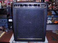
I was at a big Radio/audio show yesterday and was looking for some vintage git amp speakers...
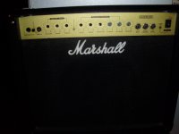
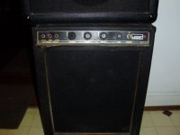
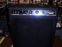
Found a couple of SS guitar amps, in not working condition,,, A Montgomery Ward Bass amp with a nice 15" Rola,,, and a newer Marshall with a 10" MG series Marshall speaker...
Also found a couple of other loose speakers, and thought rebuilding the non working amps with tube amps could make winter projects... So,,, anyone have a idea/schem for a vintage Marshall or MG/Airline tube amp I could build for either box??
I have some experience with vintage Fender circuits,,, but Marshall is new to me, and has its own unique tone, that I would like to keep with this project,,, The Marshall amp PCB appears to have been damaged(but there is no physical damage on the outside of the cab) as 6 of the[ 9 pots are sheared off the PCB, which I read was a design problem with them,,, There doesn't seem to be a schematic available for it, so the tube amp chassis seems like a good "fix"...
Thanks
Attachments
Schematic not hard to find. Here.
As ti building a tube amp in either solid state amp, you will have a metal chassis and the cab with speaker. None of the rest of the parts will be of use.
As to design flaws, some people gripe that pots ar mounted right on the board, instead of flying wires. But really, the ONLY way all the pots broke off is physical abuse.
Attachments
Thank for the reply and schematic,,, I was looking last night, and came up empty... however I did read that the pots usually broke off their mounting to the PCB,,, the board is fastened to front plate by the pots and two thin plastic sticks hold the rear of the board to the chassis... horrible mounting system, which is prone to failure by bumping or even the amp tipping over... Since this seems to be a cheaply built chip amp, with broken parts,,, I would rather find a vintage Marshall tube amp schem, gut the metal chassis, and try to use the speaker (which sounds very good with my Champ project), and rebuild the nice cabinet, with its speaker,, and a Champ sized Marshall tube amp clone...
The Wards amp turns out to be made by Marlboro USA, and I found some examples of a simalar amp with their name on it,,, no schem turned up yet tho... This Bass amp has a nice 15" Rola,,,, compared to the 12" amps I found reference to,, so far... I can see using an old Airline Bass tube amp schem for this one....
Thanks again for the input....

Here's the broken pots,,, lugs are all snapped off clean,,, not sure where they ended up,, they aren't in the amp...

The Wards amp turns out to be made by Marlboro USA, and I found some examples of a simalar amp with their name on it,,, no schem turned up yet tho... This Bass amp has a nice 15" Rola,,,, compared to the 12" amps I found reference to,, so far... I can see using an old Airline Bass tube amp schem for this one....
Thanks again for the input....
Here's the broken pots,,, lugs are all snapped off clean,,, not sure where they ended up,, they aren't in the amp...
Thanks!!! This is exactly the info I needed,,, looks like EL84s,,, so they will be easier to source than EL34s or the KTxx that I saw on most of their schems... The British OPTs may be a bit different sounding, but I have some vintage PTs that should provide the right specs...
I'll experiment a bit with the speaker, see how it handles 20W of tube power,,, it sounds good with a couple Champ ckts I built so far... This SS amp also has a small reverb tank,,, not sure it can be used here tho...
I also cleaned up the SS amp in the Monty Ward bass amp,,, fixed some wiring, cleaned the pots, and it sounds good, like to find a schematic for it, to check bias but its OK for now...
I'll clean up the cab and Tolex, tighten up the grill cloth and concentrate on the Marshall!!! as soon as I finish the 5F1 Champ project!
Thanks again for the replies...
Thanks...
I'll experiment a bit with the speaker, see how it handles 20W of tube power,,, it sounds good with a couple Champ ckts I built so far... This SS amp also has a small reverb tank,,, not sure it can be used here tho...
I also cleaned up the SS amp in the Monty Ward bass amp,,, fixed some wiring, cleaned the pots, and it sounds good, like to find a schematic for it, to check bias but its OK for now...
I'll clean up the cab and Tolex, tighten up the grill cloth and concentrate on the Marshall!!! as soon as I finish the 5F1 Champ project!
Thanks again for the replies...
This circuit looks fine for my project,,, I found two other schems that are very similar, as you said...Only question I have so far, is what are the OPT specs,,, they aren't on the schems... Looked at replacement tx at ClassicTone,, Their replacement OPT is 9.2K at 8R, which is the speaker I have to work with... 6BQ5/EL34 Specs 8K PP... Think this is a good match, or should I look for a closer output tx?Build one of the 20W Marshalls.
Although they are labelled Guitar/Bass/PA they are basically the same.
This is the "PA" one: the only other Marshall amp which can fully reproduce all sounds achieved with a 100W "Plexi" Marshall head. https://www.youtube.com/watch?v=W-C9w4zluM0
Thanks...
Yeah they do sound great and a very good fit for that size combo cabinet. 20 "more than enough"watts to get "that sound" without the earsplitting volume of a 100W stack.Build one of the 20W Marshalls.
What's going on with that LTP phase-splitter stage? It looks as though the control grids are biased to 0 V, and the tail resistor is 8.2k, equivalent to 16.4k for each triode. In other words, both triodes are set at extremely cold bias.This is the "PA" one:
Normally the tail resistor will be split into two, the triode control grids returned to the junction of the two resistors, and the control grids AC coupled to the input signal and ground, respectively. Control grids are not at 0 V DC in this arrangement.
The arrangement in this schematic, however, will produce extremely cold bias, so much so that I wonder if a long-tailed pair will even work under these conditions - if the input triode is biased off, there is no signal at its cathode to drive the second triode. In other words, there will be no output from the second half of the LTP, until the input signal to the first triode is quite large.
I could imagine that serving as the Marshall "cold clipper" stage in a guitar amp, but for P.A.? We need relatively linear small-signal operation for P.A. use.
I think there's a mistake in the schematic. Or am I misunderstanding something?
-Gnobuddy
Attachments
1917 schem is posted,,, I think they came from this site,,, #s 17, 18 and 19... they may be different or revisions?
Marshall Schematics - Tube amp Schematics
Marshall Schematics - Tube amp Schematics
Thanks for the link!I think they came from this site,,, #s 17, 18 and 19... they may be different or revisions?
I looked at those three (#17, 18, 19), and all three show the same (faulty) LTP design. Control grids at 0V, single 8.2k tail resistor, 100k and 150k anode load resistors.
Is this a case of an accidental error in the first schematic, accidentally copied over to two more? Or a deliberate error in the schematic, to discourage copycats? Or does the circuit actually work as drawn (which I doubt?)

There are other strange things in these three related (identical?) schematics, such as the 320uF cathode bypass cap for the input triode. Firstly 320 uF is not a standard value (330 uF is), and secondly, 330 uF is about fifty to a hundred times bigger than it needs to be for full bypassing over the entire audio range.
Schematic #20 on the same page (Marshall 2100 Lead & Bass), by contrast, shows an LTP design which will actually work.
I wonder if anyone has tried to build the 20W designs using these schematics, and if so, what problems they encountered? The mis-biased LTP and oversized cathode bypass cap are easy enough to fix if you know what you're doing, but I wonder what circuits/values Marshall actually put in these amps?
-Gnobuddy
Well,,, I'm glad you saw that as I wouldn't have noticed it until I built the amp!!! It sounds like just what I was looking for to replace the damaged SS amp in that Marshall,,, so I, for one, would be glad to see it sorted!!!
Just guessing where the posted schem came from, but they look like original Marshall drawings...
Maybe the JMFahey will have more info....
Just guessing where the posted schem came from, but they look like original Marshall drawings...
Maybe the JMFahey will have more info....
That makes two of us!so I, for one, would be glad to see it sorted!!!
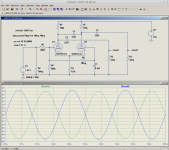
Having had all those doubts, I decided to simulate the circuit in LTSpice. The results are attached.
Unsurprisingly, LTSpice says each 12AX7 is biased to -3.5 volts, which is really cold, most of the way into cutoff - take a look at the 12AX7 datasheets to see how far to the right and down this puts the operating point.
However, to my complete surprise, LTSpice says that this crazy super cold-biased LTP actually works. The attached screenshot shows the two outputs of the PI, with the input driven by a 2V (peak to peak) input signal. What's more, the cold-biased LTP doesn't distort audibly until it's driven fairly hard - 6 Vpp at the input is still pretty linear.
While it does work, there is a penalty for operating so cold: voltage gain is a pathetic 7 times (17 dB) , instead of the roughly 25 - 30 times (~ 30 dB) we'd expect from a more conventionally biased LTP phase splitter. In other words, the cold-biased LTP has about one-fourth of the voltage gain of a more conventional one.
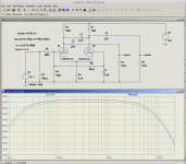
LTSpice shows a second problem (seen in the second attached image.) The signal from the volume pot to the first LTP triode is fed through an enormous 680k resistor, which acts as a low-pass filter with the input capacitance of the 12AX7 triode.
The second 680k resistor (from the second volume pot) helps out a little bit - if that volume pot is turned to zero, this 680k resistor effectively halves the source impedance to the triode, so it's effectively fed from 340k rather than 680k.
Still, this is ten times bigger than the usual 34k grid stopper at the input of a Fender amp (two 68ks in parallel), and LTSpice says it will severely limit high-frequency response: it's down 3dB at a mere 10 kHz!
This is probably plenty for electric guitar, but today, we wouldn't consider it enough for P.A. duty. Still, unsophisticated listening tests I ran on friends when I was a teenager showed that most of them would not notice a 10 kHz low-pass filter if I switched it in before they began listening to the music. (Some would notice if I switched it in while they were listening.)
Bottom line, my concerns were overblown; the circuit will in fact work as shown.
(But more voltage gain can easily be found by changing the LTP stage biasing to a more conventional setup; this may affect overdriven tone for e-guitar use, however, so it would be an experiment to try, rather than a for-sure improvement.)
-Gnobuddy
Attachments
Well,,, all I know about Marshall amps I learned from Uncle Doug!!! I can follow a schem and built a few amps,,, but finding this SS Marshall last week,, (which I only grabbed for the speaker on a Champ project),, with a damaged PCB, gave me the idea to look into a tube amp to work with the speaker and cab... Going to try to rebuild the SS amp also,, just for SnGs,, but it has pots broken off it!!!
Thanks for looking into this schem,, as I said, I wouldn't have noticed it til I built the amp... So, do you agree that it will be a good , Marshall sounding, guitar amp for this project?
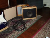
Heres the 5F1 Champ,, got it fitted in the box,, with the 8" Heppner speaker i grabbed last week also,,, sound better than the Marshall speaker in this circuit1
Thanks for looking into this schem,, as I said, I wouldn't have noticed it til I built the amp... So, do you agree that it will be a good , Marshall sounding, guitar amp for this project?
Heres the 5F1 Champ,, got it fitted in the box,, with the 8" Heppner speaker i grabbed last week also,,, sound better than the Marshall speaker in this circuit1
Attachments
The simulation tells me that the dodgy bits of this (tube) amp design do work. But they tell us nothing at all about the way it sounds (overdrives).do you agree that it will be a good , Marshall sounding, guitar amp for this project?
Personally, I have zero experience with Marshall amps - I've never owned or played through one. J.M. Fahey, on the other hand, has decades of experience with every imaginable guitar amp. He's a bit like Argentina's version of Leo Fender. I wouldn't doubt his recommendation at all (plus, he linked a video where you can hear what his recommended amp can do.)
I once tried to use a speaker from a SS guitar amp in a tube amp, and that particular speaker turned out to have a very dull sound. I think it was chosen to smooth-off some of the harsh overdrive in the SS amp. But in the tube amp, it just sounded too muffled.
I think that speaker came from a solid-state Fender amp that was called a "Princeton 65 DSP" or "Princeton DSP 65" or something like that. To my ears, it was an absolutely horrible sounding amp, on both clean and overdrive channels; I bought it cheap for the cab and 12" speaker.
-Gnobuddy
In posted the "PA version" only because it was the first one which showed up.
The actual one is the "Guitar and Bass" one so by all means follow that one.
As of how it sounds, I uploaded a modern video showing , not only that it rules, but also is basically same sound as a full blast Plexi ... what´s not to like?
The actual one is the "Guitar and Bass" one so by all means follow that one.
As of how it sounds, I uploaded a modern video showing , not only that it rules, but also is basically same sound as a full blast Plexi ... what´s not to like?
I built a 5way switch to quickly sample different speakers,,, I was leaning towards the 8" Heppner, as I built a 5F1+12" speaker, (5F2A really, I added the tone pot).. and wanted to try a Champ with a smaller speaker as it was originally... Turns out it's a good combo... The Marshall 10" has a bit more Bass to it, but sounds good enough to try the it with a Marshall tube amp...The simulation tells me that the dodgy bits of this (tube) amp design do work. But they tell us nothing at all about the way it sounds (overdrives). <snip>
We'll see as I gather parts and mock up an amp,,, probably be back with more questions!!!
Thanks again...
Thanks for all the info,, I will look thru the schems and post any with differences, to try and get the best version,,, I never heard or played thru a Marshall, either,, so looking forward to this project...In posted the "PA version" only because it was the first one which showed up.
The actual one is the "Guitar and Bass" one so by all means follow that one.
As of how it sounds, I uploaded a modern video showing , not only that it rules, but also is basically same sound as a full blast Plexi ... what´s not to like?
Thanks again...
Is this "Lead and Bass" schematic the one you are referring to?
Thanks...

There are no specs or voltages on Lead and Bass schematic,,, are the specs on older "20W PA Amp 1917" schematic accurate to use? Choke value isn't listed, older amp schems don't have a choke...
- Status
- This old topic is closed. If you want to reopen this topic, contact a moderator using the "Report Post" button.
- Home
- Live Sound
- Instruments and Amps
- Replace SS with vintage tube amps...