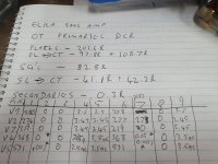
Yes there are resistors from the UL taps to the screens. My meter is working fine, all preamp tubes warm up and yes the heaters all work properly. I'm not sure why all the cathodes are 0v but I do suspect that the volume control on channel A acts as some sort of bias because if I turn it up full I get very low output but also I can hear the power tubes glass clinking like when tubes warm up or cool down
...if I turn it up full I get very low output but also I can hear the power tubes glass clinking like when tubes warm up or cool down
That should never happen? By the looks of your measured voltages, I think whatever connects the preamp tube cathodes to ground is shorted.
Also, instead of Photobucket, just upload the pictures to this forum... It works much better
Well some news....when I plug a guitar cable in the input I do get voltage on the preamp cathodes so not too sure what's going on there. 1 or 2vdc. Biased it to around 33ma. I still think it's the OT but at the same time channel B not working at all has me in doubt. There are 75ohm resistors on the UL taps.


What happen to preamp tubes plate voltages ?when I plug a guitar cable in the input I do get voltage on the preamp cathodes so not too sure what's going on there
OK, let's assume that V1 to V4 are working since their plate voltages are lower than B+ voltage .I guess V5 is drving output tubes and it's a long tail phase inverter, can you confirm? having 531V on plates and nothing on cathodes and grids ,i would check components / connections around V5 This would also explain low power at output
If you want to check OT (IMHO it's fine) With the amplifier disconnected from mains, remove output tubes, apply low AC voltage (6 ... 12 VAC should be fine) at output of OT or speaker output jack if provided (with speaker unplugged) and measure AC between plates wires at output tubes sockets.
If OT is a 3500R to 8R the voltage ratio is around 20, so applying 6V AC at output should give you around 120V AC between plates, less voltage between screens terminals.
OT is fine so I will check splitter / driver stage, check for open resistors.
If CT was unsoldered it's fine, with CT connected to B+ (with unit unpowered) you should read 0Vac
I would trace the amp schematic, not that hard and really helpfull
29vac CT to ground
If CT was unsoldered it's fine, with CT connected to B+ (with unit unpowered) you should read 0Vac
I would trace the amp schematic, not that hard and really helpfull
Last edited:
- Status
- This old topic is closed. If you want to reopen this topic, contact a moderator using the "Report Post" button.
- Home
- Live Sound
- Instruments and Amps
- OT question