I’m designing switching circuit for my amp using DPDT relays.
One relay will turn on overdrive, the other one preamp boost.
I’ll have two toggle switches on the frontal panel (to power the relay coils) and two LEDs as indicators.
I’m planning to use a footswitch too (same configuration, two switches and two LEDs) and what I’d like to achieve is this:
When the footswitch is connected the switches on the front panel must be isolated (they must not influence the power supply on the relay coils which will instead be controlled by the footswtich), however I’d like that the LEDs follow the status of those on the footswitch.

I had exactly the same thought earlier. It's the simplest solution, however, it is worth a mention that this idea requires that V+ be at about two volts greater than the voltage needed to actuate the relay. If you're running 12V relays on a 12V power supply, the extra voltage drop of the LED might stop the relay from closing reliably - the relay will only ever "see" 10 volts or so.Shunt the LED with 50-75 ohms. The 2.x volt drop across the the resistor will carry most of the current.
Also, I would suggest putting a regular silicon rectifier diode (1N4001 or similar) in reverse parallel with the LED, to protect the LED from reverse-voltage spikes when the relay is turned off.
-Gnobuddy
I had exactly the same thought earlier. It's the simplest solution, however, it is worth a mention that this idea requires that V+ be at about two volts greater than the voltage needed to actuate the relay. If you're running 12V relays on a 12V power supply, the extra voltage drop of the LED might stop the relay from closing reliably - the relay will only ever "see" 10 volts or so.
Also, I would suggest putting a regular silicon rectifier diode (1N4001 or similar) in reverse parallel with the LED, to protect the LED from reverse-voltage spikes when the relay is turned off.
-Gnobuddy
The datasheet of the 12V realay I'd like to use here https://omronfs.omron.com/en_US/ecb/products/pdf/en-g5v_2.pdf
on page 2 says it will work with 75% of rated voltage.... so maybe a 12Vcc would be enough?

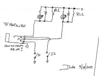
Since your relays will work on 9V, that looks like a good starting point.<circuit diagram snipped>
")
I suggest 1N4148s or 1N914s for the four protection diodes. They are easy to find, fast, and will handle the currents involved in this application.
You may find that you need to adjust the value of those 47 ohm resistors by trial and error - if they're too small, the LEDs in the foot-pedal won't light, and if they're too big, the LEDs will be too bright, and might even burn out.
Also, this is one situation where I would avoid high-efficiency LEDs - some of these will light with less than 0.1 mA, and in this particular case, that is not a good thing. Old-fashioned low efficiency LEDs that require 10 - 20 mA is what you want for this particular application.
-Gnobuddy
Since your relays will work on 9V, that looks like a good starting point.
I suggest 1N4148s or 1N914s for the four protection diodes. They are easy to find, fast, and will handle the currents involved in this application.
You may find that you need to adjust the value of those 47 ohm resistors by trial and error - if they're too small, the LEDs in the foot-pedal won't light, and if they're too big, the LEDs will be too bright, and might even burn out.
Also, this is one situation where I would avoid high-efficiency LEDs - some of these will light with less than 0.1 mA, and in this particular case, that is not a good thing. Old-fashioned low efficiency LEDs that require 10 - 20 mA is what you want for this particular application.
-Gnobuddy
Thanks for the suggestions!
Why is better to not use low current LEDs in this case?
Putting a resistor in parallel with an LED is a "touchy" circuit - if the current through the circuit is a little bit too small, the LED won't light. If the current through it is a little bit too big, the LED will be too bright, or burn out.Why is better to not use low current LEDs in this case?
I think the circuit becomes less touchy when the LED current is a larger fraction of the total current in the circuit.
Consider: if you have 20 mA LED current and 40 mA total current, you also have 20 mA in the resistor. If the 40 mA current increases by 10% to 44 mA, most of the change goes into the LED, so the LED current is up to about 24 mA, a 20% increase. That's probably acceptable.
Now suppose you have a high-efficiency LED that only needs 0.1 mA to light up. The resistor has to carry the remaining 39.9 mA. If the total 40 mA current increases to 44 mA as before, the LED current now rises from 0.1 mA to 4.1 mA. That's a 4100% increase!
The LED may cope with the 4.1 mA current, but if it was bright enough at 0.1 mA, then it will be painfully bright at 4.1 mA, maybe even damagingly bright. Nobody wants a guitar pedal with an eye-wateringly bright LED glaring up at them from a dark stage floor!
So my concern is that the circuit will be much more "touchy" with high-efficiency LEDs. The unavoidable small changes in circuit current will cause much bigger changes in LED brightness if you use high-eta LEDs.
(Those small changes in circuit current can be caused by slight changes in V+, or the change in resistance of the relay coils with temperature, or resistor temperature coefficient, or the temperature coefficient of the voltage drops across the LEDs themselves.)
-Gnobuddy
- Status
- This old topic is closed. If you want to reopen this topic, contact a moderator using the "Report Post" button.
- Home
- Live Sound
- Instruments and Amps
- Switching circuit and footswitch for new amp