Hi guys my first post here:
Recently I got a VOX AC15 tube amplifier which was smoked and I wrote about in the following link.
Error | All About Circuits
Just a summary of what happened.
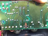
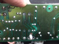
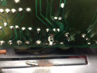
After removing the pcb I discovered that R72 was completely fried and there was visible blackening between terminal TT5 and TT7 and a conductive path was formed between the two terminals. There was a trace inbetween the terminals which was connected to the ground pour which showed signs of pitting.
What I did
I removed all the blackened pcb bits between the terminals and completely cleaned it and I filled the gap with epoxy. There was no conductivity between the terminals. I also removed the copper trace between the terminals as I couldn't understand any reason for it to be there. I replaced the blown resistor and also the HT fuse (250mA). Got fresh new tubes.
What happened
I used a 100W bulb in series to power up the amp with an 8ohm dummy load connected. I started with no tubes and then continued adding tubes one by one starting from the pre amp tubes. Each time powering down the amp and powering it up again. There were no shorts, as the light bulb remained dimmly lit. The voltage measurements taken from different points also seemed to be in check. However after a little while the light bulb seemed to go just 'slightly' bright I assumed that's because with all the tubes in and with the normal temperature that should happen.
So with no smoke or apparent short I powered it up from the mains and connected the speaker. Straight away there was a hum at about 100Hz (mains frequency here is 50Hz), turning the volume pot had no effect on the hum so I assumed bad filter caps. I injected a tone to the input and the output was amplified.
After maybe a minute or so I saw a wisp of smoke coming from the TT7 terminal area, I quickly turned off the amp. The resistors R72 and R73 was boiling hot.
What I discovered afterwards.
There were some black coloration near the TT7 terminal. I thought it might have been left from before, so just to make sure I dig out the epoxy and used a dremel to remove slightest bit of black bits. In the process of removing the pcb I noticed that connecting point to chassis ground SG1 had a high resistance reading measured with other grounding points and also it looked very tarnished so I used sand paper to clean out that point on the chassis which gave a low resistance reading to other ground points.
Since the Pcb was out I checked all the filter caps and everything seemed ok :S. I checked other components and nothing seemed out of place.
Without filling the gap between TT7 and TT5 I soldered back all the connection and powered up the amp following the procedure as before, this time I was measuring the current draw from the supply as well. This time I didn't see the slight increase in bulb brightness and it was lightly glowing all the while, and then I tried powering from the mains with the speaker connected. Current draw was about 200mA there was no smoke but the hum was still there. With a signal applied the current draw didn't vary much from the 200mA mark. I didn't want to run the amp too long with the hum so I turned it off and checked the temperature of R72 and R73 which was slightly warm to touch which I believe is normal right?
I am hoping that the smoking issue is fixed with the proper ground connection. Could it have been the culprit? Because the owner of the amp said that he saw some sparking and heard something like gunshots from the speaker before it start smoking before bringing it to me.
Now my biggest concern is the hum - the filter caps checks out ok on the multi meter removed from the circuit. However on the ESR meter I got some erroneous value, either way I have ordered new caps and waiting for them to arrive. What I worry about is since I removed the copper trace between TT5 and TT7 which was connected to the ground pour is causing the hum due to parasitic capacitance or something? I'm going to fill in the gap again with epoxy once I am soldering on the new caps.
I was hoping that you could shed some light on this matter and point me to somethings to look for
Thanks so much for the help in advance.
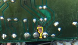
P.S I have included some photos and the schematic. In the photo named "Closeup Marked" I have marked the copper trace bit which I have removed, the think trace at the bottom is left intact.
Recently I got a VOX AC15 tube amplifier which was smoked and I wrote about in the following link.
Error | All About Circuits
Just a summary of what happened.
After removing the pcb I discovered that R72 was completely fried and there was visible blackening between terminal TT5 and TT7 and a conductive path was formed between the two terminals. There was a trace inbetween the terminals which was connected to the ground pour which showed signs of pitting.
What I did
I removed all the blackened pcb bits between the terminals and completely cleaned it and I filled the gap with epoxy. There was no conductivity between the terminals. I also removed the copper trace between the terminals as I couldn't understand any reason for it to be there. I replaced the blown resistor and also the HT fuse (250mA). Got fresh new tubes.
What happened
I used a 100W bulb in series to power up the amp with an 8ohm dummy load connected. I started with no tubes and then continued adding tubes one by one starting from the pre amp tubes. Each time powering down the amp and powering it up again. There were no shorts, as the light bulb remained dimmly lit. The voltage measurements taken from different points also seemed to be in check. However after a little while the light bulb seemed to go just 'slightly' bright I assumed that's because with all the tubes in and with the normal temperature that should happen.
So with no smoke or apparent short I powered it up from the mains and connected the speaker. Straight away there was a hum at about 100Hz (mains frequency here is 50Hz), turning the volume pot had no effect on the hum so I assumed bad filter caps. I injected a tone to the input and the output was amplified.
After maybe a minute or so I saw a wisp of smoke coming from the TT7 terminal area, I quickly turned off the amp. The resistors R72 and R73 was boiling hot.
What I discovered afterwards.
There were some black coloration near the TT7 terminal. I thought it might have been left from before, so just to make sure I dig out the epoxy and used a dremel to remove slightest bit of black bits. In the process of removing the pcb I noticed that connecting point to chassis ground SG1 had a high resistance reading measured with other grounding points and also it looked very tarnished so I used sand paper to clean out that point on the chassis which gave a low resistance reading to other ground points.
Since the Pcb was out I checked all the filter caps and everything seemed ok :S. I checked other components and nothing seemed out of place.
Without filling the gap between TT7 and TT5 I soldered back all the connection and powered up the amp following the procedure as before, this time I was measuring the current draw from the supply as well. This time I didn't see the slight increase in bulb brightness and it was lightly glowing all the while, and then I tried powering from the mains with the speaker connected. Current draw was about 200mA there was no smoke but the hum was still there. With a signal applied the current draw didn't vary much from the 200mA mark. I didn't want to run the amp too long with the hum so I turned it off and checked the temperature of R72 and R73 which was slightly warm to touch which I believe is normal right?
I am hoping that the smoking issue is fixed with the proper ground connection. Could it have been the culprit? Because the owner of the amp said that he saw some sparking and heard something like gunshots from the speaker before it start smoking before bringing it to me.
Now my biggest concern is the hum - the filter caps checks out ok on the multi meter removed from the circuit. However on the ESR meter I got some erroneous value, either way I have ordered new caps and waiting for them to arrive. What I worry about is since I removed the copper trace between TT5 and TT7 which was connected to the ground pour is causing the hum due to parasitic capacitance or something? I'm going to fill in the gap again with epoxy once I am soldering on the new caps.
I was hoping that you could shed some light on this matter and point me to somethings to look for
Thanks so much for the help in advance.
P.S I have included some photos and the schematic. In the photo named "Closeup Marked" I have marked the copper trace bit which I have removed, the think trace at the bottom is left intact.
Attachments
Is it a Vox AC15CC?
A current draw of 200 mA seems way too high to me. The two EL84's take about 85 mA with no signal. The two ECC83's take about 5 mA. The rest of the amplifier (the semi-conductors, filaments) runs on seperate windings of the power transformer so they do not contribute to the 200 mA you measure. So where is that extra 110 mA coming from?
How did you exactly measure the current?
I advise you to measure the DC voltage on the cathodes of the EL84. It should be about 10.3 V.
Greetings,
Robert
@Robert, thanks for the reply. I measured current from the primary side of the transformer. Could the lack of good grounding be the problem of the heating up? I didn't measure the current draw that time.
But after sanding down the chassis, and then when I powered on that's when I measured the 200mA from the primary side of the transformer. There is no smoke now.
An update
I have changed the filter capacitors and the 100Hz hum is now no more, well maybe just a little bit when I have the ear up close to the speaker.
I am hoping the problem is fixed. Now I am looking for good solution to secure components onto the board to mechanically reinforce it.
I will measure the cathode voltages as suggested. How much higher would be a problem?
Thanks
Hello Yambo,
I first thought that you measured the current from the secondary for the high voltage but now i understand you have measured the current at the primary (looks ok to me).
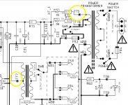
The cathode voltage in the schematic i have, is 10.25 Volts. The two EL84's share one cathode resistor of 120 Ohm. Ohm's Law (I = V/R) gives that the two EL84's draw 85 mA.
The anode voltage in the schematic i have, is 351 Volts. So minus the cathode voltage, one EL84 dissipates about 340 X 0,0425 = 14,45 Watt. That is about as high as you can go with an EL84 (allready over the limits given in the datasheets).
So you should measure not much more than 10.25 Volts at the cathodes. A little bit less looks better to me. You should also measure the anode voltages. Maybe the schematic i have (a hand drawn one) is not accurate.
Greetings,
Robert
I first thought that you measured the current from the secondary for the high voltage but now i understand you have measured the current at the primary (looks ok to me).
The cathode voltage in the schematic i have, is 10.25 Volts. The two EL84's share one cathode resistor of 120 Ohm. Ohm's Law (I = V/R) gives that the two EL84's draw 85 mA.
The anode voltage in the schematic i have, is 351 Volts. So minus the cathode voltage, one EL84 dissipates about 340 X 0,0425 = 14,45 Watt. That is about as high as you can go with an EL84 (allready over the limits given in the datasheets).
So you should measure not much more than 10.25 Volts at the cathodes. A little bit less looks better to me. You should also measure the anode voltages. Maybe the schematic i have (a hand drawn one) is not accurate.
Greetings,
Robert
Hi Robert,
Thanks for the explanation, the schematic I have got also shows similar values as you mentioned.
Now I'm looking for a good solution, to secure the components on to the board. I don't want to use hot glue. I am looking for a solution which I can get from the local hardware store. Would RTV silicon be good? Have you got any suggestions?
Once again thanks so much for the help.
Please don't use RTV silicon - it releases acid (acetic acid) as it cures, and the acid is very bad for printed circuit boards, soldered joints, and delicate metal parts....secure the components... Would RTV silicon be good?
Acetic acid is the same thing as vinegar. It's a relatively weak acid, but it's still enough to do damage to the delicate copper traces and small solder joints of a PCB.
There are silicone adhesives that do not release acid, though I've never used one.
I'm sorry I don't have a better answer for you.
-Gnobuddy
Acid curing silicone will destroy your pcb and components over time, its a classic mistake!
And its not the same as vinegar, its glacial acetic acid which is much more corrosive - it leaches out of the silicone gradually so continues to destroy for ages.
Acid-curing is also called acetoxysilane silicone.
And its not the same as vinegar, its glacial acetic acid which is much more corrosive - it leaches out of the silicone gradually so continues to destroy for ages.
Acid-curing is also called acetoxysilane silicone.
- Status
- This old topic is closed. If you want to reopen this topic, contact a moderator using the "Report Post" button.
- Home
- Live Sound
- Instruments and Amps
- Trying to repair a Smoked Vox AC15 amplifier