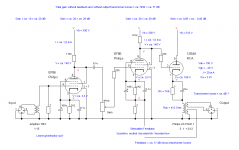
I want to build a dual mic preamp.
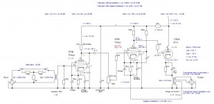
The output transformers are from a Philips AG7600 organ amplifier with 800 Ohm loudspeakers and 2 x ECL86 (one per channel) as output tubes. The turns ratio is about 3:1 (7K-800 Ohm).
The transformers have a separate winding (originally for hum-suppression) wich i want to use for feedback (with 3 positions: neutral / somewhat boosted high / somewhat boosted low).
Probably not the best transformers for the job but i want to use parts i allready have (the input transformers i had to buy though).
On an other forum i was advised to first try without a gridresistor at the first EF86. If this would turn out (too) noisy, i should try high valued resistors.
Advise is welcome.
Greetings,
Robert
Attachments
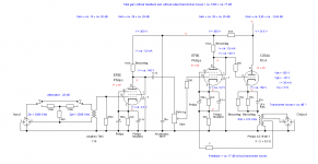
Meanwhile the schematics for this project evolved to these.
The remaining problem is how to calculate the value of the feedback resistor (and should the 100 Ohm resistor in the cathode-lead of the second EF86 have an other value?).
So advise is still welcome.
Greetings,
Robert
The remaining problem is how to calculate the value of the feedback resistor (and should the 100 Ohm resistor in the cathode-lead of the second EF86 have an other value?).
So advise is still welcome.
Greetings,
Robert
Attachments

> how to calculate the value of the feedback resistor (and should the 100 Ohm resistor in the cathode-lead of the second EF86 have an other value?).
What is the goal? Audio gain or a desired amount of NFB?
In either case, a resistor-box or potentiometer will find an answer real fast. Faster than I can think math.
What is the goal? Audio gain or a desired amount of NFB?
In either case, a resistor-box or potentiometer will find an answer real fast. Faster than I can think math.
Hi PRR,
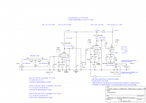
My goal is a total gain of 60 dB.
But there is an issue with my design (explained to me on an other forum). The gain of the second stage (29 dB) is about the same as the loss in the OPT when looking at the winding intended for NFB. So NFB this way is impossible in my design.
My calculation of the total gain without NFB was also wrong (i forgot that the OPT steps down so at the secondary there is about 0,33 less voltage than at the primary). The right figure is 67 dB without NFB.
I am considering the following solutions:
1) Forget about the NFB from the transformer (and maybe use the winding for level indication) and leave the cathode resistor of the second stage unbypassed
so to get rid of (part of) the 7 dB surplus.
2) Higher the gain of the second stage.
With an EBC91 (6AV6) and Ra = 220K i would get an extra 8 dB.
With the EF86 in pentode mode and Ra = 100 K i would get an extra 13 dB.
With EF86 in pentode mode and Ra = 220K i would get an extra 16,7 dB.
Downside of the EF86 in pentode mode is that Va is relatively low (60 to 80 V) which means that the direct coupling with the 12B4A also has to be re-designed. With the EBC91 Va would be 160 V, which is way closer to the current design.
Greetings,
Robert
Attachments
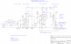
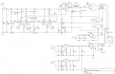
Yes, forget using the 0.12 ratio winding. That's for a loudspeaker. (It is likely too low for a level indicator.)
Take NFB from the primary. There is very little advantage taking NFB from a tertiary winding.
The value of "R?" should be 10X the to-ground NFB resistor. It should also be higher than the design load of the 12B4, which seems to be 5k-6k. 10r gives 1k which is too low a load. We need >5k at "R?", which leads to >500r at the to-ground resistor. Hey, we have a 1K right there! Throw out two caps and a resistor, run 10k from primary to cathode.
Not done yet. The self-bias EF86 is now 909r instead of 1k, no big deal. But there is 7VDC at primary, so 0.66V at cathode, before EF86 current flows. I suspect the EF86 could run at much less than 2.4mA, work it out.
Attachments
Thanks again for your advise, PRR.
I will try my original plan first, but if that failes, i will try your plan. If both fail, i will have to find better OPT's.
The schematics are pretty much done. Time to start to build.
Greetings,
Robert
I will try my original plan first, but if that failes, i will try your plan. If both fail, i will have to find better OPT's.
The schematics are pretty much done. Time to start to build.
Greetings,
Robert
Attachments
- Status
- This old topic is closed. If you want to reopen this topic, contact a moderator using the "Report Post" button.
- Home
- Live Sound
- Instruments and Amps
- Mic preamp - advise is welcome