I would like to create a tube-based "sustain pedal", increasing gain as the signal decays. The AVC (automatic volume control) and AGC (gain) circuits for AM radio are well known, but I have not found many examples which adjust audio signals rather than the intermediate frequency or transmission frequency. The closest I have found are this patent and perhaps the following paper (I am not a member of IEEE and cannot download it): US2849546A - Compressor circuit - Google Patents Audio automatic volume control circuit - IEEE Conference Publication The patent actually performs the opposite task of my target by compressing strong signals rather than increasing the gain for weak ones, and doing so manually rather than automatically. Are there templates which I have missed? If not, is there a more expedient solution than a 6D6 followed by an 85 (with the diodes in the 85 suppressing gain in the 6D6 via G3)?
Think about it, compresses strong signals then lessens as the signal fades. That is just a different way of saying as the signal fades, the level is boosted. Compressor is what you want, and the music industry is full of them.
I used to restore jukeboxes, and the amplifiers in those usually incorporate an auto level control.
I used to restore jukeboxes, and the amplifiers in those usually incorporate an auto level control.
Um, excellent design but ... the OP stated
I guess having the word "valve" in the designer´s name is not enough to qualifytube-based

As of:
The AVC (automatic volume control) and AGC (gain) circuits for AM radio are well known, but I have not found many examples which adjust audio signals rather than the intermediate frequency or transmission frequency.
the principles of RF companders apply to audio just fine, provided you scale the frequency response appropriately.
Well, sort of.
Big difference is that rectifying signal peaks (any frequency, RF or Audio) does not give you a smooth clean control voltage, but one which still contains some audio but worse, "thumps" at a low frequency but which is still real close to Audio frequencies.
So in an AM radio a very crude diode+capacitor combination shifting bias big time in earlier stages causes no problem, because RF is *decades* higher and IF transformers straight do NOT pass this annoying low frequencybthump.
Nor any Audio frequencies.
But same in a controlled gain preamp is a mess; it will thump, "breathe", duck and take ages to recover, a mess.
So Tube Audio compressors in general do rectify, do change bias to affect gain ... but are designed as push-pull stages end to end, and rely on balancing signals at output transformer to null out annoying thumpy control signal.
Which makes them large, heavy and complex.
No big deal in Rack mounted Studio equipment, I guess way too much to fit in a pedal.
The late Fred Nachbaur included a compressor option in his (tube) guitar amp design, "Spunky": "Spunky" Tube Amplifier
I don't know how "thumpy" this might be. Perhaps the use of a small speaker and output transformer filters out enough bass to make the remaining thumping acceptable.
I've never been happy with any of the DIY compressors I built, so these days I use an ART Tube MP/C: Access to this page has been denied.
The MP/C is priced at $130 (USD) now (it used to be $100 until recently.) I do not think it is possible to build a DIY compressor with anything even close to the features and capabilities of the MP/C for the same money (just the box, connectors, knobs, switches, and LED metering will suck up most of that budget if you DIY.)
Other than the MP/C, I don't think you can buy an equally good compressor without spending two to three times the price, either.
I find it a really useful little tool. I've used it with vocals, bass guitar, and guitar, and it performed well with all of them. You can also turn off the compressor and use it as a preamp, DI box, or to supply phantom power to a condenser mic.
The one thing this nifty little box doesn't do is stereo. As far as I know, there is no way to link two of them together for proper stereo compression.
By the way, I have no connection whatsoever with the manufacturer. I just like this particular product a lot.
-Gnobuddy
Talk about taking the long and roundabout route.
-Gnobuddy
I don't know how "thumpy" this might be. Perhaps the use of a small speaker and output transformer filters out enough bass to make the remaining thumping acceptable.
I've never been happy with any of the DIY compressors I built, so these days I use an ART Tube MP/C: Access to this page has been denied.
The MP/C is priced at $130 (USD) now (it used to be $100 until recently.) I do not think it is possible to build a DIY compressor with anything even close to the features and capabilities of the MP/C for the same money (just the box, connectors, knobs, switches, and LED metering will suck up most of that budget if you DIY.)
Other than the MP/C, I don't think you can buy an equally good compressor without spending two to three times the price, either.
I find it a really useful little tool. I've used it with vocals, bass guitar, and guitar, and it performed well with all of them. You can also turn off the compressor and use it as a preamp, DI box, or to supply phantom power to a condenser mic.
The one thing this nifty little box doesn't do is stereo. As far as I know, there is no way to link two of them together for proper stereo compression.
By the way, I have no connection whatsoever with the manufacturer. I just like this particular product a lot.
-Gnobuddy
I think I once read about a tube compressor that actually converted the incoming audio to amplitude-modulated RF, compressed the RF, and then detected it to produce compressed audio....RF is *decades* higher...
Talk about taking the long and roundabout route.
-Gnobuddy
Which makes them large, heavy and complex.
No big deal in Rack mounted Studio equipment, I guess way too much to fit in a pedal.
Yes, this is both out of scope for the pedal, and over my head anyway.
The late Fred Nachbaur included a compressor option in his (tube) guitar amp design, "Spunky": "Spunky" Tube Amplifier
Fred's "how it works" compressor link takes us here:
"Li'l 4x4" Compressor Option
He realized 9db of compression with a simple circuit. Without a reference point (as I have never used the commercially available compressors) is that enough?
He rejects the remote cutoff pentodes I was planning to use due to the difficulty of applying up to 50V to the suppressor grid. Actually the 6D6 would not require quite 50V, but shouldn't the diodes in a type 85 tube support this anyway?
Can you tell us the intended usage, i.e., what are you planning to do with it?...9db of compression...is that enough?
Nachbaur was using his compressor for live music. With live music, personally, I dislike heavy compression on anything (bass, guitar, vocals). I think too much compression sucks the life out of music by removing the dynamics.
When I use a compressor, I never set it for more than 6 dB of compression, maximum. More than that, and the music starts to sound increasingly "canned", dead, stiff, lifeless, to me.
But I don't know what your tastes are, and it's possible you might feel very differently from me - so I have no idea if 9 dB of compression will make you happy, or not. There are genres of recorded music that compress the living daylights out of the music, and there are plenty of people who like those types of music too.
I'm not quite sure if I understood your question, but I believe the issue is that Nachbaur derived his control voltage from the voltage across the loudspeaker....the difficulty of applying up to 50V to the suppressor grid. ..shouldn't the diodes in a type 85 tube support this anyway?
The "Spunky" is rated at 8 watts, which means at full output you have 8 volts RMS across an 8 ohm speaker. That's less than 12 volts peak. Even if you rectify it with a solid-state diode as Nachbaur did, the maximum control voltage you can get from his circuit is probably around ten or eleven volts.
Obviously at less than full power the available control voltage will be even less.
The link you posted is actually for another Nachbaur amp design, the "Lil 4x4" (not the "Spunky"). For this amp he designed a voltage-doubler circuit to generate the control voltage, and also had good things to say about a remote-cutoff tube he tried: "Li'l 4x4" Compressor Option
-Gnobuddy
Last edited:
Agreed. I think Nachbaur specifically mentions he was trying to make his guitar sound louder given the low power amp he was using - he wanted the compressor so it would increase the average loudness of his instrument.compressing the whole mix is one thing, but for guitar, a compressor is essentially a sustain pedal.
Lots of compression takes away dynamics and IMO it tends to make a guitar sound rather generic and lifeless. But a few guitarists (like Adrian Belew) built their styles around extreme amounts of compression, finding other ways to add some texture to their sound.
Still, they often ended up sounding almost like an electronic keyboard, which may have actually been what they were after: these guitarists invariably came from the 1980s, the period when popular music was heavily infested with electronic keyboard and synth sounds, and guitarists found themselves suddenly filled with insecurity and keyboard-envy.
-Gnobuddy
Motorola make an 8pin chip that has a 13dB gain and attenuates up to 80dB.
I have used them in many disco and PA systems to auto level the audio signal.
All you do is rectify the output to convert it to a dc level and feed it to pin 2.
MC3340P Datasheet
I have used them in many disco and PA systems to auto level the audio signal.
All you do is rectify the output to convert it to a dc level and feed it to pin 2.
MC3340P Datasheet
Here is one , symmetrical no thump and no user controls. Uses grain of wheat 'valves'.
But you could add a fade between one and two stage.
Simple discrete Sziklai pre
-
But you could add a fade between one and two stage.
Simple discrete Sziklai pre
-
The link you posted is actually for another Nachbaur amp design, the "Lil 4x4" (not the "Spunky"). For this amp he designed a voltage-doubler circuit to generate the control voltage, and also had good things to say about a remote-cutoff tube he tried: "Li'l 4x4" Compressor Option
Serendipitously, the 6BJ6 works as a direct plug-in replacement for the 4AU6/6AU6 in the Li'l 4x4 circuit. The pinout is slightly different, i.e. the G3/IS and K connections are reversed, but since these are tied together anyway it makes no difference.
Yes and no. Frank did revert to a remote cutoff pent., but I believe he tied G3 to the cathode rather than using it as an "active" suppressor grid receiving its own signal from a diode downstream (or the speaker downstream).
It seems that the compressor circuits are DC versions of negative feedback. Using DC enables certain tools for modification of the feedback (like caps to delay it), but can also resulting in the "thumping".
Are there examples of AC compression via dynamically variable NFB?
mea culpa maximaUm, excellent design but ... the OP stated
I guess having the word "valve" in the designer´s name is not enough to qualify
Others have mentioned Fred Nachbaur, also see the Dogzilla bass amp which has a compressor built in (here and here). (Any amp with a tremolo/vibrato can also do compression if you replace the oscillator with an AM detector)
Bruce Vicknair posted an EF86 compressor (here or hereabouts in 2017 - can't find the link today) based on US PATENT 2,766,331
Also see Ken Stone's VCA
Same basic idea : modulate the screen grid on a pentode designed for VGA use
Last edited:
Tube ones? Don´t think so, variable gain or vari-mu is a straightforward solution.Are there examples of AC compression via dynamically variable NFB?
SS?: many do so, from CDS cells triggered optically (typically by a Led) to Fets to transconductance Op Amps feeding back some of the output signal.
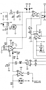
As an example, this is Peavey DDT circuit:
U1b output signal on pin 7 is attenuated and fed into U2 input, pin 2 .
It´s actually a house numbered CA3080 OTA.
Its output is fed back into U1b input pin 5, and how much of it depends on rectified distortion signal detected by U3a, so it compresses when it detects distortion (DDT) by varying NFB around U1a , so varying its gain.
Attachments
variable gain or vari-mu is a straightforward solution
Which brings me back to my variable mu 6D6!
An incremental change in G3 bias can suppress Gm from 800 to 100 (-32 to -42V).
When someone such as Nachbaur (infinitely more knowledgeable than I) states that the remote cutoff "would have made the circuitry fairly complex" , I fear that I am missing something...
Or was this complexity caused by his tapping of the speaker voltage (post OPT) for control as that voltage is so low? Are his issues addressed just by tapping the signal prior to the OPT?
Thanks for that! It certainly makes rudimentary AGC and basic compressor design very simple.Motorola make an 8pin chip that has a 13dB gain and attenuates up to 80dB.
Getting a good control signal for complex musical signals is a challenge in itself. I remember how proud Signetics was of their true-RMS control voltage generation circuitry when they released the NE570/571 compander chips.
The affordable guitar compressors I've tried (DIY or commercial) tend to introduce rather obtrusive artifacts unless you use the compression with a light touch. The sharp initial transient of a guitar note tends to burst through the compressor before the control signal has time to do anything to tame it.
-Gnobuddy
I think you'd have to buffer the signal. Compressors need to be capable of a fast attack time, which means that somewhere in the control circuitry there is a capacitor that needs to be charged up in (at most) a few milliseconds. This will demand some current, perhaps more than you can readily get at the output transformer primary side.Are his issues addressed just by tapping the signal prior to the OPT?
You can reduce the capacitance to help with this problem, but then you run into another issue: the decay constant generally has to be quite long (at least hundreds of milliseconds, maybe as much as a second or two), so if you use a small capacitor to get a fast attack, you now have to use very large resistance values to achieve a sufficiently slow decay.
Better-behaved compressors have often used clever tricks such as self-adjusting attack and decay constants that automatically vary with signal voltage. I think I first saw this in a discrete version of ye olde Dolby B noise reduction circuit, itself a type of compressor/expander that works only at treble frequencies.
For those too young to have heard of Dolby B, it was a key technical advance that made audio compact cassette players sound less-bad than before.
-Gnobuddy
For those too young to have heard of Dolby B, it was a key technical advance that made audio compact cassette players sound less-bad than before.
Too young for Dolby B? My collection includes vinyl for 78 RPM, recorded from inside to outside!
- Status
- This old topic is closed. If you want to reopen this topic, contact a moderator using the "Report Post" button.
- Home
- Live Sound
- Instruments and Amps
- Automatic volume control for audio rather than radio