Hi
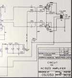
I was wondering where to measure the bias from on this model AC50 MK2 OS/053. The schematic shows set bias point coming off the two 220k resistors would this be the point to measure the the voltage coming off each tube (17.5)? , or could I measure across the 800 ohm resistor and set to -35v as the schematic states which is right in the 70% dissipation range for the EL34.
I Have also replaced the 800 ohm resistor to an 827 ohm as the original was reading around 600 ohm on the LCR and was badly burnt up. Would I need to tweak the bias slightly to accommodate this higher resistance also?
Cheers
Attachments
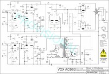
The bias voltages indicated in OS/044, -32 to -35v, will therefore have been brought closer to the values later expressed in OS/053, -32v to -40v. Presumably the range -32v to -35v was felt to be too limiting, running less strong EL34s too hard.
The neon is a coarse type of regulator.
Set the -ve bias to whatever you want from cold to hot.
See schematic;
The neon is a coarse type of regulator.
Set the -ve bias to whatever you want from cold to hot.
See schematic;
Attachments
Last edited:
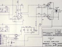
Great thanks. Installing resistors from the cathodes to ground sounds like a good idea. Also i was thinking of working out the individual plate dissipation of each EL34 by measuring the resistance on each side of output transformer, and dividing the voltage drop by the resistance X plate voltage. Schematic shows pin 7 of the rectifier runs to the centre of the output transformer but runs through a 22ohm resistor first. I was wondering if this method would work? or would the resistor make the transformer resistance measurement inaccurate.
The voltage drop across the transformer winding is a fairly accurate way to measure, assuming no signal is present. The 22R resistor will not affect the readings. As it is before the tank capacitor, it cannot be used to measure the current accurately as it forms part of a reactive supply with the rectifier and mains transformer inductance.
Ah I see so the plate voltage reading will be inaccurate using this method. Looking over the original hand drawn schematic the voltage drops to 490v from 480v by the time it reaches the plates of the output tubes. So im thinking installing cathode resistors to ground and measuring across those instead would be a better option to determine plate dissipation?.
Cheers
Cheers
- Status
- This old topic is closed. If you want to reopen this topic, contact a moderator using the "Report Post" button.
- Home
- Live Sound
- Instruments and Amps
- Set Bias Vox AC50 MK2 (GZ34 Version) OS/053