No need to yell, I was polite with my misunderstanding. I thought the whole point was to show off the little cabinet, why bother with it otherwise? I still do not see much value in your waving your microphone around when you have one near field that I guess was there for looks. My comments still stand, an A/B pedal with comparable speakers in each cabinet would have been my way to go showing off my technology if I wanted to be taken seriously.
There were three cabinets there, the Upsetter 110, the Reformer 112 and the Radical 212H. We used the 110 to discuss the design, the 112 was the one demo'd and the 212H was discussed briefly at the end.
The nearfield mic was there because that's how Rob normally captures guitar sound. As Rob explained in the video, he suggested using the boom mic to demonstrate the variance in on and off-axis response of the cabs.
This was an impromptu video where I turned up with the cabs for Rob to review them and he changed his method because of the difference he heard vs a conventional cab. It was not a video arranged by Barefaced Audio to demonstrate this patent pending technology in laboratory conditions.
Linkwitz Lab - Loudspeaker Design
Are we to wade through the whole site? If you do not have the interest in making your point what makes you think we want to spend the time sifting through the site to make it for you?
I had hoped that those posting on diyAudio might want to actually understand the truth about loudspeakers, polar response, room interaction and so on. There are few better places online to learn such things, than from one of the late pioneers of audio, Siegfried Linkwitz.
Loudspeakers
Room Acoustics
I'll respond with your own words:Duh...
If you think a single driver monopole with a beam blocker can have comparable power response to a dipole system with a diffracting waveguide on the rear, then I suggest you head over here and start reading:
Linkwitz Lab - Loudspeaker Design
It's not making it any louder on-axis, it's just improving the power response by using the rearward output to provide lots of well dispersed output. So you don't have to turn up as loud to hear yourself and you don't end up with a huge spike in output when you're in the line of fire but struggle to hear it when you're off to the side.
Makes everything easier!
Improving the power response is exactly what a beam blocker does. So you don't end up with a huge spike in output when you're in the line of fire but struggle to hear it when you're off to the side.
Makes everything easier.
The difference is a beam blocker does it on the front where it's more effective.
I'll respond with your own words:
The difference is a beam blocker does it on the front where it's more effective.
That's what you think. I'll just have to wait until you hear one.
I am sorry to see this thread starting to turn acrimonious and beginning to smoulder at the edges.
I have no emotional investment in this fight, but I would like to learn more about this interesting new cab design before forming an opinion. IMO that is always the wise thing to do.
IMO, what would be very interesting to see is some polar frequency responses. Both a Barefaced and a generic non-AVD speaker cab, both cabs with identical external dimensions to produce the same diffraction and baffle-step effects, both cabs containing the same speaker; one polar response for each cab in a highly reverberant environment (tiled bathroom, glass-walled office, etc), one polar response in something close to an anechoic environment (out on the lawn far from all large hard objects will probably do well enough.)
Turning to beam-blockers, I will say that I have tried more than one DIY beam-blocker, and I have always found them utterly lacking and pretty much useless. They are crude devices going back to the early years of loudspeaker design, a time when the typical loudspeaker manufacturer understood very little of how loudspeakers actually work.
The history of the "beam blocker" goes back at least seventy-one years, as Gilbert Briggs describes one that he made in his 1948 (!!) book "Loudspeakers: The why & how of Good Reproduction". That book was published long before I was born, but I found and read a copy at the local library when I was a boy.
The "beam blocker" idea (and close relatives based on hemispherical or conical reflectors with straight or parabolic shapes) is based on the mistaken belief that the majority of the high frequencies are only radiated from the dust-cap and the area of the speaker cone immediately surrounding it. This isn't actually true of the bothersome frequencies from guitar speakers. If it was true, then we wouldn't need a beam blocker in the first place, because all the treble would be coming from a small region the size or a Hi-Fi tweeter, and treble would disperse beautifully on its own!
So the whole idea of the beam-blocker is based on lack of understanding of both speakers and diffraction. Blocking off the centre of a speaker cone doesn't actually do what the happy beam-blocker inventor imagines it does! (I have never seen a manufacturer-supplied polar frequency response plot showing a beam-blocker doing what it's supposed to; have you?") )
)
The real problem isn't that the speaker is radiating treble only from its centre; the problem is that the entire cone radiates frequencies sufficiently high in frequency that the diameter of the cone is too large compared to the wavelength of these treble frequencies. Blocking off the centre does nothing to solve this. A good tweeter isn't shaped like a 12" diameter ring! And if you made one, it wouldn't work, because such a ring also beams treble like a lighthouse!
There is a better way. What is actually needed is to block the outer part of the speaker cone, not the centre. This has the effect of reducing the speaker's effective diameter. If you Google "Mitchell Doughnut" you'll turn up information on a rather clever way of doing that. (There is a cost, you lose some treble, and might have to turn the treble tone control on your amp up a little to compenste.)
I don't want to discuss the Mitchell Doughnut further here, as this thread is about the new technology in Barefaced Audio guitar cabs, not about DIY approaches to managing treble beaming from guitar speakers.
-Gnobuddy
I have no emotional investment in this fight, but I would like to learn more about this interesting new cab design before forming an opinion. IMO that is always the wise thing to do.
IMO, what would be very interesting to see is some polar frequency responses. Both a Barefaced and a generic non-AVD speaker cab, both cabs with identical external dimensions to produce the same diffraction and baffle-step effects, both cabs containing the same speaker; one polar response for each cab in a highly reverberant environment (tiled bathroom, glass-walled office, etc), one polar response in something close to an anechoic environment (out on the lawn far from all large hard objects will probably do well enough.)
Turning to beam-blockers, I will say that I have tried more than one DIY beam-blocker, and I have always found them utterly lacking and pretty much useless. They are crude devices going back to the early years of loudspeaker design, a time when the typical loudspeaker manufacturer understood very little of how loudspeakers actually work.
The history of the "beam blocker" goes back at least seventy-one years, as Gilbert Briggs describes one that he made in his 1948 (!!) book "Loudspeakers: The why & how of Good Reproduction". That book was published long before I was born, but I found and read a copy at the local library when I was a boy.
The "beam blocker" idea (and close relatives based on hemispherical or conical reflectors with straight or parabolic shapes) is based on the mistaken belief that the majority of the high frequencies are only radiated from the dust-cap and the area of the speaker cone immediately surrounding it. This isn't actually true of the bothersome frequencies from guitar speakers. If it was true, then we wouldn't need a beam blocker in the first place, because all the treble would be coming from a small region the size or a Hi-Fi tweeter, and treble would disperse beautifully on its own!
So the whole idea of the beam-blocker is based on lack of understanding of both speakers and diffraction. Blocking off the centre of a speaker cone doesn't actually do what the happy beam-blocker inventor imagines it does! (I have never seen a manufacturer-supplied polar frequency response plot showing a beam-blocker doing what it's supposed to; have you?
)The real problem isn't that the speaker is radiating treble only from its centre; the problem is that the entire cone radiates frequencies sufficiently high in frequency that the diameter of the cone is too large compared to the wavelength of these treble frequencies. Blocking off the centre does nothing to solve this. A good tweeter isn't shaped like a 12" diameter ring! And if you made one, it wouldn't work, because such a ring also beams treble like a lighthouse!
There is a better way. What is actually needed is to block the outer part of the speaker cone, not the centre. This has the effect of reducing the speaker's effective diameter. If you Google "Mitchell Doughnut" you'll turn up information on a rather clever way of doing that. (There is a cost, you lose some treble, and might have to turn the treble tone control on your amp up a little to compenste.)
I don't want to discuss the Mitchell Doughnut further here, as this thread is about the new technology in Barefaced Audio guitar cabs, not about DIY approaches to managing treble beaming from guitar speakers.
-Gnobuddy
Amazing response from these drivers. They go up to 5000kHz & some even to 5500kHz Barefaced Upsetter 110
– Barefaced Audio LOL, of course they are mistakes I'm surprised nobody has spotted them until now
@ alexclaber
It seems that you have actually produced something new/novel, even if it incorporates existing ideas etc, & should therefore normally expected to be granted a patent, & i hope you do But, as far as i've been aware for years, you are supposed to keep it secret until After the patent is granted ?
– Barefaced Audio LOL, of course they are mistakes
I'm surprised nobody has spotted them until now @ alexclaber
It seems that you have actually produced something new/novel, even if it incorporates existing ideas etc, & should therefore normally expected to be granted a patent, & i hope you do
But, as far as i've been aware for years, you are supposed to keep it secret until After the patent is granted ?...up to 5000kHz & some even to 5500kHz...of course they are mistakes
I looked up the manufacturer's datasheet for the Celestion G10, and I would say there is no mistake - the G10 has quite a wide frequency response for a guitar speaker. See attached image.
-Gnobuddy
Attachments
How I see the cabinet, a slot loaded horn/port, I can see it producing a gain in acoustic output, over what range? For the 'truth' on loudspeakers, depending on what your intent is. Do you want a better sound field? Heck I get that with my open back cabinets. In some situations that is not a bad thing, in live situations it can be a plus or minus depending on the type of band you are and where you play. Fender has been putting out dipol cabinets for a long time, not new and not a secret.
As far as high frequencies and beaming, yes the loudspeakers do. And yes the highs do get radiated more from the center of the cone rather than the whole surface of the diaphragm. Part of the reasons why we have cones with wizzers, the center gets decoupled from the rest of the cone at high frequencies. If you are unsure of it, stick a mic at different parts of the cone. A Celestion K12H-100 with a wizzer cone, on centre and 45 degree off axis plots. Seems they do the 45 degree plot for PA type speakers of theirs.
As far as high frequencies and beaming, yes the loudspeakers do. And yes the highs do get radiated more from the center of the cone rather than the whole surface of the diaphragm. Part of the reasons why we have cones with wizzers, the center gets decoupled from the rest of the cone at high frequencies. If you are unsure of it, stick a mic at different parts of the cone. A Celestion K12H-100 with a wizzer cone, on centre and 45 degree off axis plots. Seems they do the 45 degree plot for PA type speakers of theirs.
An externally hosted image should be here but it was not working when we last tested it.
I worked side-by-side with two loudspeaker designers for a couple of years; they change the glue used to attach the speaker cone to the voice coil, depending on how much they want the cone to decouple (or not) from the voice coil.Part of the reasons why we have cones with wizzers, the center gets decoupled from the rest of the cone at high frequencies.
For ancient-technology "whizzer cone" full range speakers, there are two tricks played to encourage the whizzer to take over at high frequencies: soft rubbery glue is used to attach the cone to the voice coil former, and often concentric circular rings are pressed into the cone itself, encouraging outer parts of the cone to be only loosely coupled to the central areas.
Most guitar speakers don't have these concentric circular grooves, rubbery glue isn't used to attach the cone to the voice coil former because you need the big cone to make all the treble you can, and the cone itself isn't particularly designed to break up until you get somewhere near the highest frequency the speaker makes (the big peak you usually see just before the response falls like a rock.)
But the treble-beaming problem starts long, long before you get to this very highest frequency the guitar speaker can manage. We don't hear shrieky 5 kHz stuff - we hear shrieky stuff starting by maybe 500 Hz - 600 Hz and up! The speed of sound in air at room temp is about 340 m/S; a 12" speaker (30 cm dia) is a half-wavelength at 567 Hz.
Sound from two opposite edges of the cone are completely out of phase 90 degrees off-axis at this frequency, so the speaker is already becoming directional, and only becomes more so as the frequency climbs above 570 Hz. By 1.2 kHz we have quite a lot of beaming, by 1.8 kHz the speaker is beaming like a lighthouse, and we may still have the entire cone moving as one piece because we're still well below that cone breakup up at 3.5 kHz or 4kHz.
(And those dual cone full-range speakers? Remember, those little "whizzer" cones are designed to fill out the top octave, say 5 kHz to 10 kHz. But guitar speakers never really venture much into that top octave at all - usually all the important stuff is below 5 kHz. We are not in whizzer territory.)
The simple proof that guitar speakers do indeed radiate their treble from most of the cone (and not just the centre) is in my previous post: IF most of the cone decoupled from the centre at high frequencies, THEN only the centre is radiating high frequencies, which means it behaves like a small tweeter, which means it produces wide dispersion.
But it does not produce wide treble dispersion. Ergo, our assumption is false. Ergo, the annoying treble frequencies are not being radiated only from the centre, but from most of the cone area.
The "mic in the centre" experiment doesn't prove what you say it does - it leads to a false conclusion, which is almost universally believed by sound engineers (but that doesn't make it any less wrong.)
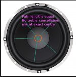
The fallacy occurs because most people think that when you point the mic at one spot on the cone, it picks up sound from just that one spot. This is simply not true - it picks up the sum of the sound fields from every microscopic point on the entire speaker cone, each of which has travelled a different distance to get to the mic, and arrives with a different phase-shift. In mathematical terms, the local sound field at the mic is the superposition of all the tiny sound fields generated by every tiny little microscopic area of the cone.
Now, when the microphone is positioned in the centre of the cone, every point on the cone is matched by another point equally distant on the opposite side of the mic (see attached image.) The signals from both regions are in phase, so you get reinforcement. So, when the mic is placed exactly in the centre, you get good treble response, as there are no sound cancellations at this on-axis location.
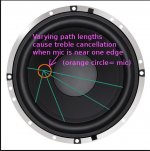
Now move the mic off-centre (second image.) Now, at treble frequencies, for many regions of the speaker cone, there will be a counterbalancing region on the other side of the cone that is half a wavelength further from the mic; those two sounds will cancel out as the signals are 180 degrees out of phase (destructive interference.)
The net result is a considerable droop in treble response at the location of the off-axis microphone. This treble loss is caused by destructive interference between sound from the differently-spaced near and far sides of the cone, and not because the edges of the cone radiate less treble than the centre.
-Gnobuddy
Attachments
I worked side-by-side with two loudspeaker designers for a couple of years; they change the glue used to attach the speaker cone to the voice coil, depending on how much they want the cone to decouple (or not) from the voice coil.
For ancient-technology "whizzer cone" full range speakers, there are two tricks played to encourage the whizzer to take over at high frequencies: soft rubbery glue is used to attach the cone to the voice coil former, and often concentric circular rings are pressed into the cone itself, encouraging outer parts of the cone to be only loosely coupled to the central areas.
Most guitar speakers don't have these concentric circular grooves, rubbery glue isn't used to attach the cone to the voice coil former because you need the big cone to make all the treble you can, and the cone itself isn't particularly designed to break up until you get somewhere near the highest frequency the speaker makes (the big peak you usually see just before the response falls like a rock.)
But the treble-beaming problem starts long, long before you get to this very highest frequency the guitar speaker can manage. We don't hear shrieky 5 kHz stuff - we hear shrieky stuff starting by maybe 500 Hz - 600 Hz and up! The speed of sound in air at room temp is about 340 m/S; a 12" speaker (30 cm dia) is a half-wavelength at 567 Hz.
Sound from two opposite edges of the cone are completely out of phase 90 degrees off-axis at this frequency, so the speaker is already becoming directional, and only becomes more so as the frequency climbs above 570 Hz. By 1.2 kHz we have quite a lot of beaming, by 1.8 kHz the speaker is beaming like a lighthouse, and we may still have the entire cone moving as one piece because we're still well below that cone breakup up at 3.5 kHz or 4kHz.
(And those dual cone full-range speakers? Remember, those little "whizzer" cones are designed to fill out the top octave, say 5 kHz to 10 kHz. But guitar speakers never really venture much into that top octave at all - usually all the important stuff is below 5 kHz. We are not in whizzer territory.)
The simple proof that guitar speakers do indeed radiate their treble from most of the cone (and not just the centre) is in my previous post: IF most of the cone decoupled from the centre at high frequencies, THEN only the centre is radiating high frequencies, which means it behaves like a small tweeter, which means it produces wide dispersion.
But it does not produce wide treble dispersion. Ergo, our assumption is false. Ergo, the annoying treble frequencies are not being radiated only from the centre, but from most of the cone area.
The "mic in the centre" experiment doesn't prove what you say it does - it leads to a false conclusion, which is almost universally believed by sound engineers (but that doesn't make it any less wrong.)
The fallacy occurs because most people think that when you point the mic at one spot on the cone, it picks up sound from just that one spot. This is simply not true - it picks up the sum of the sound fields from every microscopic point on the entire speaker cone, each of which has travelled a different distance to get to the mic, and arrives with a different phase-shift. In mathematical terms, the local sound field at the mic is the superposition of all the tiny sound fields generated by every tiny little microscopic area of the cone.
Now, when the microphone is positioned in the centre of the cone, every point on the cone is matched by another point equally distant on the opposite side of the mic (see attached image.) The signals from both regions are in phase, so you get reinforcement. So, when the mic is placed exactly in the centre, you get good treble response, as there are no sound cancellations at this on-axis location.
Now move the mic off-centre (second image.) Now, at treble frequencies, for many regions of the speaker cone, there will be a counterbalancing region on the other side of the cone that is half a wavelength further from the mic; those two sounds will cancel out as the signals are 180 degrees out of phase (destructive interference.)
The net result is a considerable droop in treble response at the location of the off-axis microphone. This treble loss is caused by destructive interference between sound from the differently-spaced near and far sides of the cone, and not because the edges of the cone radiate less treble than the centre.
-Gnobuddy
Very nicely put

I looked up the manufacturer's datasheet for the Celestion G10, and I would say there is no mistake - the G10 has quite a wide frequency response for a guitar speaker. See attached image. -Gnobuddy
Well you've gone and misread it as have lots of others ! Have another look. It says 5000kHz & 5500kHz NOTE kHz
Ah. In that case, I guess I'm as thick as the proverbial whale omlet.NOTE kHz
-Gnobuddy
Amazing response from these drivers. They go up to 5000kHz & some even to 5500kHz Barefaced Upsetter 110
– Barefaced Audio LOL, of course they are mistakes
Aarghhh!!! I can't believe they've got that wrong and that no-one here spotted it (admittedly it was a very intense session for one of our team to set up all the custom driver pages). Will get it changed asap.
@ alexclaber
It seems that you have actually produced something new/novel, even if it incorporates existing ideas etc, & should therefore normally expected to be granted a patent, & i hope you do
No, you are supposed to keep it secret until the patent submission has been made - it takes years for patents to be granted!
I looked up the manufacturer's datasheet for the Celestion G10, and I would say there is no mistake - the G10 has quite a wide frequency response for a guitar speaker. See attached image.
-Gnobuddy
I think what you mean is 5.5khz.. Or 5500hz..
5500khz is a frequency way beyond our hearing..
Yes, yes, yes. You are quite right.konakaiyak said:I think what you mean is 5.5khz.. Or 5500hz..
5500khz is a frequency way beyond our hearing...
However - we sorted out that little mental slip-up nearly two and a half years ago! See post # 30 and #31.
-Gnobuddy
Apologies for reviving a two-and-a-half-year-old thread, but I was hoping to DIY an AVD-style cab, and I'm wondering what the target frequency is of the helmholtz resonator for these cabs, and how it's determined, i.e. Is it the same for say, all the 1x12 cabs, or does it vary based on the driver?
Alternatively, if someone who has one just wanted to give me exact measurements of a 1x12 Reformer, that would also work
Alternatively, if someone who has one just wanted to give me exact measurements of a 1x12 Reformer, that would also work
Apologies for reviving a two-and-a-half-year-old thread, but I was hoping to DIY an AVD-style cab, and I'm wondering what the target frequency is of the helmholtz resonator for these cabs, and how it's determined, i.e. Is it the same for say, all the 1x12 cabs, or does it vary based on the driver?
Made a quick and dirty estimate from the first port calculator that popped up, using the 1x12 Reformer dimensions, and a WAG on the cabinet volume reduction due to the speaker and rear flat sided 90 degree parabolic horn to determine the net volume.
Fb (Frequency of Box tuning/ Helmholtz resonance) looks to be around 98 Hz .
Low E on a standard tuned 6 string guitar is 81Hz.
Guitar speakers Fs (free air resonance) ranges from ~60 to 120Hz, 100Hz being fairly common.
If the speaker's Fs matches Fb, and it's VAS (Volume of Air having the same acoustic compliance as driver Suspension) is ~the net cabinet volume, the port will provide the most low end "boom".
The 1x12 Reformer net volume is similar to the VAS of many guitar speakers.
The tight suspension/small VAS of guitar speakers keeps them from "flapping" below Fb or when used in open back cabinets.
The box Fb will be the same regardless of the driver used, other than small deviations due to the volume the driver occupies, a deeper cone and bigger magnet structure uses more volume than a shallow cone with small magnet.
A larger cone volume will raise the Fb slightly, smaller will lower the Fb.
12" guitar speakers are around 100dB using 1 watt at one meter, 10 watts makes 110dB at 1 meter, 104dB at 2 meters, 98 at 4 meters outdoors. Indoors in a small room the level might have hardly any drop.
You could use a smaller driver if you prefer to distort at a lower volume, a 6" might be as much as -10dB less sensitive than a 12", sounding half as loud. That said, smaller speakers have wider high frequency dispersion, if setting on the floor with no tilt, the smaller speaker may sound brighter than a 12".
https://www.the12volt.com/caraudio/boxcalcs.asp#porsq
The port width appears to be the slightly less than the width of the Speakon connector, so just under <24mm, or 1".
If you blow the pictures up on screen, you should be able to easily duplicate this simple cabinet.
Anyway, this is all basic speaker design, not rocket science.
Make the slot wider, Fb goes up, rear dispersion narrows, thinner, Fb drops, rear dispersion gets wider.
If you wanted to be clever, you could make the port exit width adjustable using an overlapping plate with thumb screws into T-nuts.
The little parabolic horn chamber is also a bandpass filter, boosting the rear midrange output, while cutting the highs. Lining the cabinet with damping material would reduce the high end from the horn.
Small changes in the cabinet will be similar to adjusting a tone knob.
Art
Last edited:
Appreciate the thorough reply Art! Based on your back-of-napkin math, it seems like the target Fb for all these cabs is around 100Hz, since that was roughly what I calculated from the smaller 1x10 design that's in the patent. Part of what was throwing me off was the fact that when I was trying to calculate the Fb of the 1x12, I forgot to subtract the volume of the AVD design on the back, which was giving me some numbers that were absolutely wrong, haha.
I was curious if the Fb was varied based on the driver's Fs, but I imagine that would be a nightmare from a production standpoint, so they're almost certainly all the same enclosures no matter the driver.
Regarding the back being a horn, at least according to the measurements published in the patent, the rear vent is acting more as a waveguide than a horn, so there shouldn't be any low-pass filtering, at least according to Barefaced.
- Home
- Live Sound
- Instruments and Amps
- Rear vent/diffractor cab