Welcome back! ")
If the goal is weight reduction, a single-ended output transformer is heavier than a push-pull transformer. I think any weight you save by eliminating one 6V6 will be more than gained back by having to use a heavier SE output transformer.
So if the primary goal is to reduce weight, I would focus my attention on the heaviest components (speaker, transformers, speaker cabinet), and try to reduce the weight of each of them. For example, you could use a smaller speaker in a lightweight pine cab. The power transformer could be replaced by a switch-mode power supply (a modified 220V AC inverter for use in a car contains 340 volts DC inside, and can easily power a small amp.) Heaters and AC inverter can be fed from a small 12 volt switch mode power supply.
If the goal is (B), to reduce power, can you tell us the intended use for the amp? 6 watts is too quiet to use with a drummer, and at the same time, much too loud to use at home, so the intended usage is very important.
-Gnobuddy
I'm a little confused. Is the goal (A) to make a VOX-like amp that's lighter, or (B) one that's lower power, or (C) to mate a Champ power section to a VOX preamp? (And how do you know that this will result in good tone? Have you tried this out before?)Hello!,
- The idea behind the amp is to cross the VOX ac15 preamp with a champ power section.
<snip>
I want to make a light combo amp with a superb tone.
If the goal is weight reduction, a single-ended output transformer is heavier than a push-pull transformer. I think any weight you save by eliminating one 6V6 will be more than gained back by having to use a heavier SE output transformer.
So if the primary goal is to reduce weight, I would focus my attention on the heaviest components (speaker, transformers, speaker cabinet), and try to reduce the weight of each of them. For example, you could use a smaller speaker in a lightweight pine cab. The power transformer could be replaced by a switch-mode power supply (a modified 220V AC inverter for use in a car contains 340 volts DC inside, and can easily power a small amp.) Heaters and AC inverter can be fed from a small 12 volt switch mode power supply.
If the goal is (B), to reduce power, can you tell us the intended use for the amp? 6 watts is too quiet to use with a drummer, and at the same time, much too loud to use at home, so the intended usage is very important.
I hope you are having a good time, and enjoying your holidays!Hello!,
I am travelling during my first week of holidays.
-Gnobuddy
Since you plan on going off the beaten path it might be good to ask a few questions. Do you have any building experience in tube electronics, metal forming, woodworking? Do you want an exact copy of the preamp and just mate it to the power section? Do you want both channels, want the tremolo circuit? If you want the circuit as is but only a low power output stage I would say use the Slucky documentation and build on the board as shown.
As far as the power section is concerned you could go 6V6 SE off one of the PI outputs with no problem. The 6V6 does take a little more signal than an EL84 that is in the AC-15 but the PI should have plenty of signal to drive it. As Gnobuddy has said earlier, a 6AK6 P-P output section will put out about 4W. That or the 6V6 could both be rather loud going into a efficient 12". Into a lower efficient 8-10" will give less volume and less weight. It also depends on whether you want run a clean amp or overdrive it. I think the addition of the attenuator might be a good idea. I need to try the HV inverter that are sold online (rather than modify a car inverter) on an amp, one of them and a switched 12V laptop supply should knock off the power transformer weight to a great extent.
If building your own cabinet, selecting a lightweight pine board can save some weight. I found some boards to be half the weight as the heaviest boards. A light aluminum chassis will cut down on weight also.
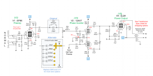
1960 Vox AC-15
As far as the power section is concerned you could go 6V6 SE off one of the PI outputs with no problem. The 6V6 does take a little more signal than an EL84 that is in the AC-15 but the PI should have plenty of signal to drive it. As Gnobuddy has said earlier, a 6AK6 P-P output section will put out about 4W. That or the 6V6 could both be rather loud going into a efficient 12". Into a lower efficient 8-10" will give less volume and less weight. It also depends on whether you want run a clean amp or overdrive it. I think the addition of the attenuator might be a good idea. I need to try the HV inverter that are sold online (rather than modify a car inverter) on an amp, one of them and a switched 12V laptop supply should knock off the power transformer weight to a great extent.
If building your own cabinet, selecting a lightweight pine board can save some weight. I found some boards to be half the weight as the heaviest boards. A light aluminum chassis will cut down on weight also.
1960 Vox AC-15
Last edited:
Since you plan on going off the beaten path it might be good to ask a few questions. Do you have any building experience in tube electronics, metal forming, woodworking? Do you want an exact copy of the preamp and just mate it to the power section? Do you want both channels, want the tremolo circuit? If you want the circuit as is but only a low power output stage I would say use the Slucky documentation and build on the board as shown.
As far as the power section is concerned you could go 6V6 SE off one of the PI outputs with no problem. The 6V6 does take a little more signal than an EL84 that is in the AC-15 but the PI should have plenty of signal to drive it. As Gnobuddy has said earlier, a 6AK6 P-P output section will put out about 4W. That or the 6V6 could both be rather loud going into a efficient 12". Into a lower efficient 8-10" will give less volume and less weight. It also depends on whether you want run a clean amp or overdrive it. I think the addition of the attenuator might be a good idea. I need to try the HV inverter that are sold online (rather than modify a car inverter) on an amp, one of them and a switched 12V laptop supply should knock off the power transformer weight to a great extent.
If building your own cabinet, selecting a lightweight pine board can save some weight. I found some boards to be half the weight as the heaviest boards. A light aluminum chassis will cut down on weight also.
1960 Vox AC-15
Hi there,
I have built a two stroke amplifier and a Vox AC4. I'm no expert at all, but I'm starting to manage.
I have a VOX AC15 heritage with the EF86 channel and it's super awesome. Every guitar I plug there shines. It's the best preamp I have heard of all the amps I have tried. Even hot humbuckers sound pristine.
Regarding weight: lightweight pine cab is no problem and I use 12" neodymium speakers, less than 2.5kg.
I love the sound of the 6V6, and it's the tube I understand better. So I deeply rely on it for the power section.
The metalwork it's not an issue. I can easily fit everything in a 5F2 or 5e3 chassis.
I would choose the usual guitar power transformers.
Thanks again. This really cheers me up with my project!
I agree that using the little pre-made inverter is much simpler. But I wasn't sure if it would support a 15-watt guitar amp, which probably draws 40 - 50 watts from the B+ rail at full output....I need to try the HV inverter that are sold online (rather than modify a car inverter) on an amp...
However, those little inverters for the car can easily be found rated for 100W or more. Unfortunately, in North America, they only contain about 170 volts DC internally, which isn't enough for most valve guitar amp designs.
But Jaidn seems to be in Spain, a country with 230 V electricity; that means the auto inverters sold in his country should have about 330 - 340 volts DC inside them already. Perfect for a small 6V6 amp! (Except for the need to find it inside the inverter, and solder on wires to bring it out.)
If output power is lowered considerably, it may be that the little Ebay module can handle it. That would certainly make life simpler, and B+ is adjustable with a screwdriver, which could also come in very handy.
Jaidn, to repeat Printer2's questions, can you tell us if you plan to include the second channel of the AC-15 as well? And the tremolo oscillator? That is a lot of stuff to fit in a 5E3 chassis, if so.
If you want to make absolutely minimal changes to the push-pull amp, I agree with Printer2's very clever suggestion: I think all you have to do is omit one output valve, change the cathode resistor on the remaining one to bias it into class A, and change the output transformer to a suitable single-ended one.
It is not usual to use any kind of phase splitter in an SE amp, but it won't hurt anything (other than wasting half of a 12AX7), and the long-tailed phase splitter will give you some of the same sound characteristics as a push-pull output stage.
-Gnobuddy
I agree that using the little pre-made inverter is much simpler. But I wasn't sure if it would support a 15-watt guitar amp, which probably draws 40 - 50 watts from the B+ rail at full output.
However, those little inverters for the car can easily be found rated for 100W or more. Unfortunately, in North America, they only contain about 170 volts DC internally, which isn't enough for most valve guitar amp designs.
But Jaidn seems to be in Spain, a country with 230 V electricity; that means the auto inverters sold in his country should have about 330 - 340 volts DC inside them already. Perfect for a small 6V6 amp! (Except for the need to find it inside the inverter, and solder on wires to bring it out.)
If output power is lowered considerably, it may be that the little Ebay module can handle it. That would certainly make life simpler, and B+ is adjustable with a screwdriver, which could also come in very handy.
Jaidn, to repeat Printer2's questions, can you tell us if you plan to include the second channel of the AC-15 as well? And the tremolo oscillator? That is a lot of stuff to fit in a 5E3 chassis, if so.
If you want to make absolutely minimal changes to the push-pull amp, I agree with Printer2's very clever suggestion: I think all you have to do is omit one output valve, change the cathode resistor on the remaining one to bias it into class A, and change the output transformer to a suitable single-ended one.
It is not usual to use any kind of phase splitter in an SE amp, but it won't hurt anything (other than wasting half of a 12AX7), and the long-tailed phase splitter will give you some of the same sound characteristics as a push-pull output stage.
-Gnobuddy
No tremolo or oscillator, just the normal preamp.
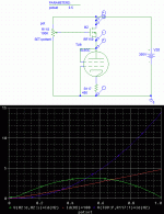
Here is the Sluckey schematic modified as little as possible, but still converted to single-ended.
One output pentode is removed, the OT is now a single-ended type (same impedance as a Champ), and the cathode bias resistor for the single 6V6 has been changed to 470 ohms, as in a Fender Champ.
The schematic still shows an EL84, because I didn't want to edit all the pin numbers. But the 470 ohm cathode resistor is, I believe, correct for a Champ, with more or less your B+ voltage.
-Gnobuddy
Attachments
I was thinking that too, 100 ohms seems too small to protect the screen grid from melting during overdrive.Maybe a 470R for R62?
I also forgot to mention that the point labelled "from Vib/Trem preamp" should be grounded. This is necessary for the phase splitter to work properly when the second channel preamp is removed.
Finally, while Fender shows 470 ohms for R60, that is really hard on the poor 6V6, overheating it well beyond its maximum rating. Depending on the actual B+ you use, you may have to increase R60 to keep the 6V6 power dissipation within ratings.
The Sluckey drawing shows 336V on the anode, and that means anode current should be kept to no more than 35 mA for 12 watts anode dissipation in the 6V6. R60 should be increased if necessary to achieve this.
-Gnobuddy
Here is the Sluckey schematic modified as little as possible, but still converted to single-ended.
One output pentode is removed, the OT is now a single-ended type (same impedance as a Champ), and the cathode bias resistor for the single 6V6 has been changed to 470 ohms, as in a Fender Champ.
The schematic still shows an EL84, because I didn't want to edit all the pin numbers. But the 470 ohm cathode resistor is, I believe, correct for a Champ, with more or less your B+ voltage.
-Gnobuddy
Absolutely KILLER!
Member
Joined 2009
Paid Member
Here is the Sluckey schematic modified as little as possible, but still converted to single-ended.
-Gnobuddy
lovely schematic! what software did you use ?
All credit for the lovely schematic goes to the mysterious Sluckey(?) - the PP version was included in Jaidn's first post in the thread.lovely schematic! what software did you use ?
All I did was take a screen-capture of that beautifully clear schematic on my Linux PC, open it up in The Gimp (free and open-source Photoshop-alike), and edit away one output valve and a few other unnecessary gubbins. I also edited the value of one resistor (the cathode resistor for the remaining single output valve.)
-Gnobuddy
lovely schematic! what software did you use ?
For those Visio people, Sluckey has the shapes in a file at the bottom of his home page. He is a moderator at el34world.com
Index: Amp projects and more...
Member
Joined 2009
Paid Member
> I couldn't quickly find a big pentode datasheet showing curves for multiple screen grid voltages
7027 data has a useful range of Vg1=0 curves for several Vg2. Since first-crack load-line is to cutoff and Vg1=0, this is a start. I don't mind you using a smaller pendode though.
I have built an amp with fixed Vp and variable Vg2. It "did a right thing" on dummy resistor. I am not sure this extends to loudspeakers with 10:1 variation of impedance at key points on the frequency range. (When "turned down" it may drive bass resonance far better than midrange.)
I will assume Vp and Vg2 are similar and track the same way; this may be the more-right way to go.
> the MOSFET VVR has to dissipate more power than the speaker attenuator does
The MOSFET dissipation is milder than you might expect. If the amplifier is modeled as a resistor, then half-voltage is half-current. At this point both tube and resistor dissipate 1/4 of what the tube alone dissipated at 100%. For a 14W plate dissipation, 50% gives 3.5W in tube and 3.5W in MOSFET.
In an actual tube, Voltage varies directly but current falls-off as Child's Law, a little faster than voltage. Then worst-case for MOSFET happens near 53%, and for 14.3W tube at 100% the worst-case for the MOSFET is 3.4W. So assuming the tube "is a resistor" is very close and conservative. Max MOSTFET dissipation is 1/4 of 100% tube dissipation.
Contrast to speaker attenuator. The 14W tube(s) will make 5.6W SE or could be 8W push-pull. Assuming we attenuate to bedroom level, <1W, the speaker attenuator must have a peak dissipation of 5W-8W. But only when playing LOUD. Unless you head-bang (quietly) ALL night, the average pad dissipation will be far less. The tube dissipation is high all the time.
The MOSFET reducer basically cooks steady. However at bedroom level (20%-40%): 20%: 2W MOSFET 0.4W tube; 40%: 3W MOSFET 2W tube.
It is kinda a wash, except the MOSFET dropper is less total electric bill and heat in the room. If we only had a 1,000 Watt bedroom amp(!!) then the dissipation differences would be important. But we can build a Champ or DeLuxe nearer a dozen watts, with another dozen Watts in heaters and losses, and not much care about the penny/hour electric cost or the tenth-degree rise of room temp.
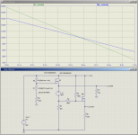
In dummy-sim: Generic tube (could be 6V6 etc), self-biased, all non-DC parts ignored. V(M).. is voltage across the MOSFET, V(TU)... is voltage across the tube+bias, I(M) is current which is the same in MOSFET and tube (no gate current). The multiplications compute the power in each part. Tube heat falls-off, MOSFET heat peaks near 50% on pot, at about 1/4 of tube max heat.
The red line is current. If a tube were a perfect resistor this would be straight. Child's Law (a fair approximation on real tubes) says it curves. Indeed, from 48mA@100% we go to 22mA@50%, where a resistor would be 24mA. Close enough for rock.
There is an added glitch because the MOSFET needs 4V to turn on at all, and the tube is slow to rise from zero, so the <5% zone is "dead". In experiment, anything under 10% starts to sound "broken" because the current has fallen-off faster than the voltage which screws bias and loading. In practice we put a stopper under the bottom of the pot to give some low-point like 15% or 8% depending on designer taste.
7027 data has a useful range of Vg1=0 curves for several Vg2. Since first-crack load-line is to cutoff and Vg1=0, this is a start. I don't mind you using a smaller pendode though.
I have built an amp with fixed Vp and variable Vg2. It "did a right thing" on dummy resistor. I am not sure this extends to loudspeakers with 10:1 variation of impedance at key points on the frequency range. (When "turned down" it may drive bass resonance far better than midrange.)
I will assume Vp and Vg2 are similar and track the same way; this may be the more-right way to go.
> the MOSFET VVR has to dissipate more power than the speaker attenuator does
The MOSFET dissipation is milder than you might expect. If the amplifier is modeled as a resistor, then half-voltage is half-current. At this point both tube and resistor dissipate 1/4 of what the tube alone dissipated at 100%. For a 14W plate dissipation, 50% gives 3.5W in tube and 3.5W in MOSFET.
In an actual tube, Voltage varies directly but current falls-off as Child's Law, a little faster than voltage. Then worst-case for MOSFET happens near 53%, and for 14.3W tube at 100% the worst-case for the MOSFET is 3.4W. So assuming the tube "is a resistor" is very close and conservative. Max MOSTFET dissipation is 1/4 of 100% tube dissipation.
Contrast to speaker attenuator. The 14W tube(s) will make 5.6W SE or could be 8W push-pull. Assuming we attenuate to bedroom level, <1W, the speaker attenuator must have a peak dissipation of 5W-8W. But only when playing LOUD. Unless you head-bang (quietly) ALL night, the average pad dissipation will be far less. The tube dissipation is high all the time.
The MOSFET reducer basically cooks steady. However at bedroom level (20%-40%): 20%: 2W MOSFET 0.4W tube; 40%: 3W MOSFET 2W tube.
It is kinda a wash, except the MOSFET dropper is less total electric bill and heat in the room. If we only had a 1,000 Watt bedroom amp(!!) then the dissipation differences would be important. But we can build a Champ or DeLuxe nearer a dozen watts, with another dozen Watts in heaters and losses, and not much care about the penny/hour electric cost or the tenth-degree rise of room temp.
In dummy-sim: Generic tube (could be 6V6 etc), self-biased, all non-DC parts ignored. V(M).. is voltage across the MOSFET, V(TU)... is voltage across the tube+bias, I(M) is current which is the same in MOSFET and tube (no gate current). The multiplications compute the power in each part. Tube heat falls-off, MOSFET heat peaks near 50% on pot, at about 1/4 of tube max heat.
The red line is current. If a tube were a perfect resistor this would be straight. Child's Law (a fair approximation on real tubes) says it curves. Indeed, from 48mA@100% we go to 22mA@50%, where a resistor would be 24mA. Close enough for rock.
There is an added glitch because the MOSFET needs 4V to turn on at all, and the tube is slow to rise from zero, so the <5% zone is "dead". In experiment, anything under 10% starts to sound "broken" because the current has fallen-off faster than the voltage which screws bias and loading. In practice we put a stopper under the bottom of the pot to give some low-point like 15% or 8% depending on designer taste.
Attachments
I'm sure I've seen those sorts of curves for several output pentodes, but for the life of me, I can't remember any of them right now. This is where an actual paper book of tube datasheets would come in handy, rather than downloading PDFs one at a time off the 'Web!7027 data has a useful range of Vg1=0 curves for several Vg2.
Now, that is very interesting indeed. I've been overestimating MOSFET dissipation substantially, in part because of reading anecdotal tales of people putting enormous heatsinks on their VVR and still frying the MOSFET.For a 14W plate dissipation, 50% gives 3.5W in tube and 3.5W in MOSFET.
It would be really nice if we can get power scaling over two orders of magnitude (15W down to 150 mW). In principle that requires voltage to scale by one order of magnitude - in practice probably less than that, so it seems possible.In practice we put a stopper under the bottom of the pot to give some low-point like 15% or 8% depending on designer taste.
-Gnobuddy
Yes, I noticed that, and found it encouraging.100% to 15%-8% is about one OoM.
I hope to have some useful information to contribute to the subject later today, but right now, work calls.
-Gnobuddy
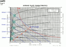
I found that the manufacturer of the 6AF11 Compactron thoughtfully provided pentode curves at a number of different screen voltages. So I spent a little time tinkering with load-lines.
The goal was to learn more about the relationship between screen voltage (Vg2) and anode voltage (Va) for optimum power scaling. The load-lines assume an output transformer, so that anode voltage can rise above B+ voltage during some portion of the audio signal.
I've made some simplifying assumptions in order to be able to work with the limited data we have available to us.
"Optimum power scaling" in this case was assumed to mean that (a) the load line always passed through the knee of the pentode curves, and (b) the operating point always stayed at the centre of the load-line, for pure class A operation.
For class AB push-pull output stages I think it would be reasonable to assume that the operating point should always be located at a fixed percentage of the way up the load-line (less than 50%) from the lower right-hand corner. That would preserve roughly the same degree of "AB-ness", i.e. how warm the bias is compared to pure class B, with zero quiescent current. I don't think this will change the broad conclusions drawn from the pure class A example.
Okay. Item one: the attached set of pentode curves for the 6AF11, taken at screen voltages from 50 V to 150 V in 25V steps.
6.6k looked like a reasonable load. I used 6.67k rather than 6.6k simply because it makes it easier to plot the load lines. The difference is utterly insignificant when it comes to an actual transformer.
I've plotted one 6.67k load-line slap-bang through the centre of the knee of each of the pentode curves, for Vg2 = 50,75,100,125, and 150V respectively. (This is shown by the pale green dots.)
We can now find the mid-point of each load-line (orange dots), and the corresponding voltage by dropping a perpendicular to the x-axis.
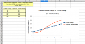
We now have several screen voltages, and the optimum anode voltage for each of them, to place the operating point right in the middle of the load line.
Item two: I put those numbers into a spread-sheet, and plotted them (second image.)
When the screen voltage is very low (50 V), the optimum anode voltage is about 35V. Put another way, the optimum screen voltage is greater than the anode voltage at low anode voltages.
As the screen voltage is increased, the optimum anode voltage increases faster, and at some point the curves cross over; at high screen voltages, the optimum anode voltage is higher than the screen voltage. Put another way, the optimum screen voltage is lower than the anode voltage at high anode voltages. (Of course this is exactly what we are used to in the vast majority of guitar amps, which have no power-scaling.)
For power-scaling purposes, it may be easier to visualize starting at full B+ (anode voltage), and lowering it from there. The conclusion is that we should start out with screen voltage below anode voltage, but as we reduce anode voltage, the screen voltage should fall less rapidly, until at some point it crosses over and becomes greater than the anode voltage.
I do not know how universally applicable this conclusion might be - does it apply to all pentodes? All beam tetrodes? Only this particular pentode from the 6AF11? It's hard to be sure, but I suspect it will, in fact, apply broadly to all or most pentodes and beam tetrodes.
It's tempting to think of applying modern electronics to crack this particular nut - use an Arduino or similar cheap microcontroller to measure the anode voltage, use a look-up table to find the optimum screen voltage, and set the screen voltage accordingly using a D/A converter and power MOSFET. That would allow fine-tuning by ear for the most consistent guitar tone over the entire range of power scaling. All the magic would be in the numbers stored in that look-up table.
The Arduino I used doesn't have a built-in D/A converter, but there is probably a more powerful model that does. The Arduino can only spit out voltage up to +5V, so there would need to be a little voltage amplifier between Arduino and power MOSFET.
I'm sure we could also get "close enough for jazz" with a potentiometer, a handful of resistors, and a couple of MOSFETs. This is presumably what Kevin O'Connor did, very successfully, several decades ago. Smart man.
Note that this entire post is based only on data for Vg1 = 0; zero volts at the control grid. That's because that's the only data available in the 6AF11 data-sheet. There is a big chunk missing from this analysis, because we didn't / couldn't look at Vg1 (control grid) voltage scaling. But it may be somewhat reasonable to believe that "what happens at zero volts, happens at non-zero volts"; in other words, the broad conclusions probably apply even if we had used, say, curves for Vg1=(-5V) at various Vg2 to perform the analysis.
-Gnobuddy
The goal was to learn more about the relationship between screen voltage (Vg2) and anode voltage (Va) for optimum power scaling. The load-lines assume an output transformer, so that anode voltage can rise above B+ voltage during some portion of the audio signal.
I've made some simplifying assumptions in order to be able to work with the limited data we have available to us.
"Optimum power scaling" in this case was assumed to mean that (a) the load line always passed through the knee of the pentode curves, and (b) the operating point always stayed at the centre of the load-line, for pure class A operation.
For class AB push-pull output stages I think it would be reasonable to assume that the operating point should always be located at a fixed percentage of the way up the load-line (less than 50%) from the lower right-hand corner. That would preserve roughly the same degree of "AB-ness", i.e. how warm the bias is compared to pure class B, with zero quiescent current. I don't think this will change the broad conclusions drawn from the pure class A example.
Okay. Item one: the attached set of pentode curves for the 6AF11, taken at screen voltages from 50 V to 150 V in 25V steps.
6.6k looked like a reasonable load. I used 6.67k rather than 6.6k simply because it makes it easier to plot the load lines. The difference is utterly insignificant when it comes to an actual transformer.
I've plotted one 6.67k load-line slap-bang through the centre of the knee of each of the pentode curves, for Vg2 = 50,75,100,125, and 150V respectively. (This is shown by the pale green dots.)
We can now find the mid-point of each load-line (orange dots), and the corresponding voltage by dropping a perpendicular to the x-axis.
We now have several screen voltages, and the optimum anode voltage for each of them, to place the operating point right in the middle of the load line.
Item two: I put those numbers into a spread-sheet, and plotted them (second image.)
When the screen voltage is very low (50 V), the optimum anode voltage is about 35V. Put another way, the optimum screen voltage is greater than the anode voltage at low anode voltages.
As the screen voltage is increased, the optimum anode voltage increases faster, and at some point the curves cross over; at high screen voltages, the optimum anode voltage is higher than the screen voltage. Put another way, the optimum screen voltage is lower than the anode voltage at high anode voltages. (Of course this is exactly what we are used to in the vast majority of guitar amps, which have no power-scaling.)
For power-scaling purposes, it may be easier to visualize starting at full B+ (anode voltage), and lowering it from there. The conclusion is that we should start out with screen voltage below anode voltage, but as we reduce anode voltage, the screen voltage should fall less rapidly, until at some point it crosses over and becomes greater than the anode voltage.
I do not know how universally applicable this conclusion might be - does it apply to all pentodes? All beam tetrodes? Only this particular pentode from the 6AF11? It's hard to be sure, but I suspect it will, in fact, apply broadly to all or most pentodes and beam tetrodes.
It's tempting to think of applying modern electronics to crack this particular nut - use an Arduino or similar cheap microcontroller to measure the anode voltage, use a look-up table to find the optimum screen voltage, and set the screen voltage accordingly using a D/A converter and power MOSFET. That would allow fine-tuning by ear for the most consistent guitar tone over the entire range of power scaling. All the magic would be in the numbers stored in that look-up table.
The Arduino I used doesn't have a built-in D/A converter, but there is probably a more powerful model that does. The Arduino can only spit out voltage up to +5V, so there would need to be a little voltage amplifier between Arduino and power MOSFET.
I'm sure we could also get "close enough for jazz" with a potentiometer, a handful of resistors, and a couple of MOSFETs. This is presumably what Kevin O'Connor did, very successfully, several decades ago. Smart man.
Note that this entire post is based only on data for Vg1 = 0; zero volts at the control grid. That's because that's the only data available in the 6AF11 data-sheet. There is a big chunk missing from this analysis, because we didn't / couldn't look at Vg1 (control grid) voltage scaling. But it may be somewhat reasonable to believe that "what happens at zero volts, happens at non-zero volts"; in other words, the broad conclusions probably apply even if we had used, say, curves for Vg1=(-5V) at various Vg2 to perform the analysis.
-Gnobuddy
Attachments
> at some point the curves cross over; at high screen voltages, the optimum anode voltage is higher than the screen voltage. Put another way, the optimum screen voltage is lower than the anode voltage at high anode voltages.
Yes, that trend is general. Getting away from wee pipsqueak tubes: look at 6550. For some conditions around 400-450V supply, Vg2 is "near" Vp. But for MAX conditions it is near Vp=600V, Vg2=300V. As you get into transmitter tubes (which do have different Mu(g2) you may find Vp=1500V Vg2=400V. The real high voltages don't need high signal current, thus don't need high Vg2.
There's two "optimums" here. If you *accept* the extra cost of a separate Vg2 supply, then an "optimum" is low Mu(g2) and low Vg2 with high Vp. However in *audio* we like to be cheap/simple. Vg2 is usually 80%-99% of Vp, just one more filter-drop down. This leads to Mu(g2) like 10 for good voltage sensitivity (because we feed the driver 70%-90% of Vp and can't stand low voltage sensitivity).
Now turn-down. Yes, if "optimum" is defined as MOST power at a GIVEN % on the turn-down knob, then Vg2 should scale different from Vp. But-but-but-- who cares? What we want is a smooth turn-down AND (as always) minimum cost, complication, unreliability.
Also: your analysis was for "known" load slicing through the knee (what the vet just did to my dog). When we face a loudspeaker we have a rough idea of minimum impedance and for-sure some impedance peaks 5+X higher. So great precision in Vp:Vg2 ratio is probably folly.
Also you *can* run Vg2 higher than "necessary". The drawbacks are higher peak currents into faults, and higher G1 bias and drive. We can usually cover some extra G1 (and not hitting the Vg1 knee reduces blocking). The peak current and potential blow-up: bah, tubes are tough and cheap, and we have to work hard to kill them.
So Let Vg2~~Vp, and at 100% let Vg2 be a little higher than "perfect". (Fender's voltages tend to be this way.) By mid-turn it will be "near optimum". By 15% it may be "below optimum" meaning it clips earlier than simple Vp predicts. Well, this is the "less" end of the scale so "less" is just what the user is demanding. It does a right thing.
Attachments
Last edited:
Certainly not me. The reason I'm interested in keeping the load-line passing through the knee (or a consistent few % below it) is for consistent TONE, not for max power. This was discussed extensively earlier in this thread, in the back-and-forth between myself and Bigun. For a pentode, the quality of overdrive distortion changes dramatically as the load-line swings above and below the knee of the curves, and this is the opposite of what we want when power-scaling....if "optimum" is defined as MOST power at a GIVEN % on the turn-down knob, then Vg2 should scale different from Vp.
But-but-but-- who cares?
I also tried to keep the operating point the at the same percentage of the loadline above the lower-right corner for the same reason - preserving overdriven tone. This keeps the output stage consistently at the same amount of class AB-ishness (bias doesn't effectively become hotter or colder, moving either towards or away from pure class B), which should also help to keep tone consistent as the power scaling knob is turned.
How about getting Vg2 and Va linearly coupled and crossing over in just the right spot for the cost of one zener diode, one pot, and one small MOSFET that handles only the wee screen current, five times less than anode current?What we want is a smooth turn-down AND (as always) minimum cost, complication, unreliability.
The light-bulb came on in my head an hour ago, see attached schematic. (R2+R4 can be a linear pot, and sets the rate at which Vg2 falls wrt Va. V1 is a Zener or other voltage reference, and sets how far Vg2 is below Va when Va is at its maximum (= B+). Beautifully simple.
For analysis purposes, keep the signal frequency the same as the power scaling knob is turned, and the speaker impedance will stay constant. Or plug in a dummy load. To get anywhere when trying to create a mathematical model of a physical phenomenon, we have to strip away variables that complicate the analysis needlessly, unless they are absolutely vital. I can't think of a reason why a speaker impedance curve will affect a 1W amp differently than a 10W one, so I don't think it's a relevant variable here.Also: your analysis was for "known" load slicing through the knee (what the vet just did to my dog).
So: there is more than one way to skin a cat, or scale a poweramp...
Caveman approach: no power scaling at all.
First-order improvement: Scale Va and Vg2 equally.
Second-order improvement: Scale Va and Vg2 linearly, at different slopes, with an offset, for more consistent overdrive tone as the power scaling knob is turned.
Third-order improvement: a microcontroller with a look-up table, so Va and Vg2 are optimized over a wide range of power-scaling.
The caveman approach has worked well for us for decades, Leo Fender and Jim Marshall made a nice living from it. The first-order improvement you're proposing is betterer. For the cost of a small MOSFET, one pot, and one Zener, I would say the second-order improvement is worth trying, as it may be even better-er-er by a smidge, if it turns out to keep tone more consistent as power is scaled. That would need to be established one way or the other by trying it out.
-Gnobuddy
Attachments
- Status
- This old topic is closed. If you want to reopen this topic, contact a moderator using the "Report Post" button.
- Home
- Live Sound
- Instruments and Amps
- Vox AC15 EF86 with one power tube