You'll have to redesign the phase inverter to be a mixing stage with suitable gain to drive a single-ended 6V6 power amp. The push-pull output transformer will need to be replaced by a suitable single-ended (gapped) transformer. The top-cut control will need to be replaced by something like a Garnet feedback tone control (assuming you want to retain that bit). There are likely to be other tweaks I'm overlooking. It probably won't sound much like the original circuit, though. The phase inverter contributes to the tone as does the push-pull EL84 output stage. That doesn't mean it won't sound good, just different.
You would get closer to AC-15 vibe, I think, by power-scaling existing EL84 power amp and adjusting the OT primary impedance to run the amp at 7-to-10 watts.
Stph
You would get closer to AC-15 vibe, I think, by power-scaling existing EL84 power amp and adjusting the OT primary impedance to run the amp at 7-to-10 watts.
Stph
Why not turn the volume down ... ?
Isnt it common to like when an amp distort because turn it up higher than it can play clean? I thought that was the reason lowpowered guitaramps has become so popular
Going from push-pull to single-ended won't make the amp as much quieter as you'd expect, because of the way the human ear works. In fact, going from 15 W to 6 W is only about 4 dB SPL reduction, which is quite a slight change to the ear....Sluckey's Vox AC-15...I don't need 15W.
On top of that, SE output stages do sound different from PP. In my opinion, SE output stages produce better clean tones, while PP outputs produce better distorted / overdriven tones. (Of course "better" is entirely subjective, and you may or may not share my opinion.)
You have to change almost everything in the power amp, including the OT. In effect, you would be designing a new amp, or bolting something a lot like a Fender Champ output stage onto your VOX EF86 preamp. Even if you do this, there's no telling if you'll like the result, so it will be an experiment....modify or transform the amp from PP to SE...
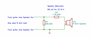
So I would suggest you consider making a simple speaker attenuator instead. You only need two power resistors to make a simple fixed attenuator. You can quite easily cut the power from nominally 15 W to nominally 6 W, and see if that quietens it down enough for you (it may very well not.)
The attached schematic shows you how simple this is. You need two power resistors, which only cost a few bucks.
Consider the power ratings shown in the schematic a minimum. You can use a 50 W resistor for R1 and a 25 W resistor for R2 if you want a little more safety margin (cooler-running resistors.)
Remember, 6W can be very loud...this attenuator will do what you asked for (turn a 15W amp into a 6 W amp), but, depending on how you plan to use the amp, it may still be louder than you want.
It's not hard to change the values of R1 and R2 to lower the output power to less than 6 watts, and I've already made a spreadsheet of values you could use if it turns out that 6W is too loud for you.
-Gnobuddy
Attachments
That's one of the problems with valve guitar amps, they only produce the timbre you want at one specific setting, which happens to generate the amount of nonlinear distortion you want from the output stage. Unfortunately, that setting may very well be too loud, depending on your intended use.Why not turn the volume down ... ?
I did some calculations a few years ago that suggested that a few tens of milliwatts of power is all you need for apartment-friendly loudness levels from an overdriven guitar amp connected to a typical guitar speaker. As far as I know, there are very few commercial guitar amps that let you dial down the output that far.
Not long ago I breadboarded a single-ended guitar amp using a small-signal pentode as the output device, putting out a thundering 200 milliwatts or so at full chat. There's barely enough output power to warm up a quarter-watt 8 ohm resistor, but it was too loud to overdrive in my apartment at night!
(Clean tones were quite usable, though.)
-Gnobuddy
It occurs to me that one might build a PP power amp with a 7699 dual-pentode (see attached data sheet) or a similar wideband amplifier. These sorts of tubes were used in Tektronix oscilloscopes. The 7699 ought to be good for around a 1-2 watt power amp into a 10K plate-to-plate load. There were several industrial variants of this sort of thing used in scopes. Other tubes to consider for this sort of low-power PP amp, would AGC sync tubes such as the 6BU8, 6GS8 or 6KF8.
This sort of low-power PP amp would get much closer to the Vox AC15 vibe than a SE output stage. At 1/10 the power it would seem about half as loud (give or take).
Stph
This sort of low-power PP amp would get much closer to the Vox AC15 vibe than a SE output stage. At 1/10 the power it would seem about half as loud (give or take).
Stph
Attachments
One might indeed, and it might be an interesting experimental project. But there is a chance it may not sound much like the Sluckey-simplified Vox the OP wants....one might build a PP power amp with a 7699 dual-pentode...or a similar wideband amplifier.
")
Along the lines of your proposal, a few years ago I built a small push-pull 2 watt amp using a pair of little 7-pin 6AK6 pentodes as the output valves. I paid $3 each for these. The 6AK6 was originally designed for audio output in radios, and has a 2.75-watt anode dissipation rating.
My more recent 200 mW single-ended experiment used a one-buck 6JW8, a 9-pin triode-pentode valve originally designed to be used in televisions. The pentode section is rated for only 1.2 watts maximum anode dissipation, the same as each of the two triodes in a 12AX7!
For my 6JW8 design, the OT primary needs to be about 20 - 25k, which I got from a little Hammond transformer, though a Fender reverb transformer would probably also work. There are only a few milliamps of DC anode current, and output power is miniscule, so my small PP output transformer seems to have no difficulty at all coping with SE usage.
The triode in the 6JW8 is used as the driver for the pentode, and I used a second one-buck valve (6AQ6) as the input gain stage. There is enough gain to insert a tweaked Fender two-knob tone control between 6AQ6 and 6JW8 triode, and go from clean tones to something in the classic rock era.
I agree on both counts. And I'll add that half as loud as a 15-watt Vox is still very, very loud, depending on where you intend to use it!This sort of low-power PP amp would get much closer to the Vox AC15 vibe than a SE output stage. At 1/10 the power it would seem about half as loud (give or take).
For what it's worth, with a proper guitar speaker attached, my little 6AK6 is far too loud to overdrive in my apartment. Which is why I decided to try out a ten-times-less-powerful 200 mW amplifier design on the bread-board.
-Gnobuddy
My little SE build based on a 12DW7 (milliAmp test bed) was quiet enough to talk over. I'd be surprised if it topped a 1/4 watt; probably close to your 200 mW design.For what it's worth, with a proper guitar speaker attached, my little 6AK6 is far too loud to overdrive in my apartment. Which is why I decided to try out a ten-times-less-powerful 200 mW amplifier design on the bread-board.
-Gnobuddy
Stph
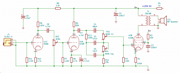
Certainly close power-wise. Here's the schematic of the final version I tested on the breadboard. I felt it still needed some tweaking to sound its best....probably close to your 200 mW design.
Incidentally, that's not grid-leak bias at the output stage; the control grid of the output pentode gets its ground reference through the tone control pots and R11. LTSpice simulation showed that this particular tone control circuit had very good performance, as long as the output was essentially unloaded - the usual 1 meg load was far too low, and ruined the tone control contours. I used the 10M resistor to offer some safety to the pentode stage if the treble tone control pot goes bad.
I used a bench supply to power the breadboarded prototype; had I gone beyond prototyping, the plan was to use a small 120V:120V mains isolation transformer or a small switching boost converter to generate B+, and power the heaters with a small SMPS wall-wart.
One of the things I never did was explore how it worked as a Herzog, though that had been part of the original intention.
-Gnobuddy
Attachments
@Gnobuddy if you ever finish a truly low watt ampdesign I hope you make a thread about it. I believe I love some of Mesa Boogie's 2x12 inch cabinets. Just have to find out exactly which. Would be nice to hear that powered by a good "fleawatt" poweramp in the livingroom. Should be cheaper to build with such low power.
Then go the full way and build your cabinet tooI believe I love some of Mesa Boogie's 2x12 inch cabinets. Just have to find out exactly which. Would be nice to hear that powered by a good "fleawatt" poweramp in the livingroom. Should be cheaper to build with such low power.
What you will actually listen to is the speakers, into a proper sized box.
Copy any one you fancy, no need to even Tolex it, just have some tasty MDF cut to size and juditious application of nails and glue plus a few hammered thumbs will turn that into a cabinet *sounding* as good as the Mesa one.
Looks? .... WHAT looks ?
In fact it´s easier to mate it to room decor so less "family problems"; you may paint it in any colour you (she) fancies or plain cover it with a piece of black cloth and make it "disappear".
The point is you fill it with any speakers you fancy, from a couple "metal" V30 to a wider range classic combination of Greenback and G30H , the sky is the limit.
Did I mention it´s very DIY and you will save a lot?
Yes I guess I should. Im just a little nervous, cause I once when very young, build a cabinet for a brand new celestion 12 inch driver, that cost me a fortune. Didnt know what I was doing, and it sounded awful. Anyways my next build in that department are with 4 norvegian 5inch fullranges from the 50ies that I saved from a radiostation ages ago. Will take time and opportunity to listen to mesa boogies to find which models I liked so much
Hello there!,
I love the Sluckey's 1960 Vox AC-15. I'd like to modify it to fit a single 6V6 power tube (I don't need 15W). What do I have to modify o transform the amp from PP to SE single tube?
I attach the Sluckey's 1960 Vox AC-15 pdf.
Cheers!
Hope we haven't scared him away. If I were to be inclined to run a single channel AC-15 for less power I would make an adapter to go from the 9-pin socket to go to a 7-pin and run a 6AQ5 in place of a 6V6. But if you are stuck on a 6V6 then do the adapter thing with an 8-pin socket. It might be a lot of tube/adapter sticking, part of the reason for the 6AQ5. Then there is the 6CM6, a 9-pin 6V6. Just rewire the grid, screen and plate, the heaters use the same pins. Might want to buy a few while they have them.
6CM6 Audio Tubes - www.thetubestore.com
Once that is taken care of, remove the other EL84 and connect a 10k/20-25W resistor from the plate pin and the cathode pin. This balances the current through the output transformer. Next lift the cathode side of R60 and hook up a 330R resistor from the cathode to ground. The phase inverter is fine, the amp runs a 1.2k resistor and it is fine. So other than the 10k 20W resistor and the 330R cathode resistor with a 6CM6, you should be fine. Well, it might not hurt putting a resistor to draw the heater current of the missing EL84.
Member
Joined 2009
Paid Member
what's wrong with some simple power scaling instead, wouldn't that be easier ?
What I means is, add a source follower to feed the screen grids of the output tubes and with a pot on the gate you can adjust the screen voltage down. This will compress the plate curves, lowering the current for a given drive signal. It has the benefit of reducing tube dissipation too. It won't sound exactly the same of course, because the lower current will mean less B+ sag induced distortion although adding some series resistance to the rectifier could compensate.
What I means is, add a source follower to feed the screen grids of the output tubes and with a pot on the gate you can adjust the screen voltage down. This will compress the plate curves, lowering the current for a given drive signal. It has the benefit of reducing tube dissipation too. It won't sound exactly the same of course, because the lower current will mean less B+ sag induced distortion although adding some series resistance to the rectifier could compensate.
That was the first thought that crossed my head, but a two-resistor speaker attenuator is considerably simpler.what's wrong with some simple power scaling instead, wouldn't that be easier?
There are plenty of bad speaker attenuators out there, but we now know that the key factor is for the attenuator to present a high output resistance to the loudspeaker, just like the output pentodes in the amplifier itself do when there is no attenuator. As long as this is done, the speaker produces much the same EQ curve as it does without the attenuator, and there is minimal change to the sound quality.
(An aside: this business of high output impedance of valve guitar amps, and the need to maintain that in a speaker attenuator, first crossed my mind a couple of years ago. I posted something about the concept on diyAudio, and I got a response from another member, John D.H., who had the same idea, and had taken it much farther than I had; he had built a series of speaker attenuators around the concept, and he had the measurements to prove that the concept worked. His post is #48 in this thread: https://www.diyaudio.com/forums/ins...l-amp-ot-primary-impedance-5.html#post5518847 )
Let me say up front that I have zero experience with power scaling....you can adjust the screen voltage down. This will compress the plate curves...it won't sound exactly the same...
That said, scaling only the screen grid voltage will, as you say, push the anode curves down. But it will leave the load line in the same place as before. This means the load line will now move from "below the knee" at the top left corner of the curves, to "above the knee".
For an SE output stage, at least, this produces a rather drastic change in overdriven timbre of the output stage. An "above the knee" load-line produces heavily asymmetric triode-like distortion with lots of even harmonics, while the usual "below the knee" load line for guitar amp output stages compresses one half of the waveform at relatively small signal amplitude, but compresses both ends of the waveform as amplitude approaches maximum, shifting towards mostly odd-harmonic distortion.
It's possible that the effect is reduced for a PP output stage. Each output valve is only handling one half-cycle, but even so, moving the load-line will change the way the peaks of the half-cycles start to distort as the amp is progressively pushed into deeper overdrive. And that surely changes the "feel" of the amp, as well as the overdriven tone; I would guess that as the load line swings further above the knee of the curves, the onset of clipping will become much more abrupt and less progressive.
So my belief is that both screen grid voltage, and anode voltage, of the output valves have to be scaled to stand any chance of maintaining a (nearly) constant timbre.
To explore this further, a while ago I plotted load-lines on a set of curves for the same (SE) pentode at different screen-grid voltages, and found that the relationship between the "knee" of the curves and the load line could be maintained nearly constant if both screen grid voltage and anode voltage were decreased at the same time - but not in the same ratio.
That is to say, as the B+ dropped, the screen grid voltage needs to drop more slowly. Screen grid voltage starts out lower than anode voltage, but as the anode voltage is reduced further, there comes a point where screen grid voltage would need to be higher than anode voltage.
I posted those graphs to diyAudio a couple of years ago, but have no memory as to what thread they were posted to, and haven't had any luck finding it with the forum search function.
I know Kevin O'Connor worked out how to do good power scaling decades ago, but I've never seen any of his books; the prices are too high for me, particularly given the lack of any information on how good the content actually is. At any rate, based on KOC's claims of extreme power-scaling with no change in tone (!!!), I expect KOC figured out the same thing, as well as a way to implement simultaneous scaling of screen grid and anode voltages by different ratios.
This would be very easy to do if we had 400-volt op-amps. But with simple discrete circuitry, it is trickier to separate DC offset voltages from DC voltage gains, and I haven't come up with a reasonable circuit design that I like, yet. To be fair, I haven't put much thought into it, either.
-Gnobuddy
Tom Schlangen's Homepage - Tube DIY Pages
I said this another time, build the octal mojo.
You can remove part of your circuit, just use the driver of 1 output tube. I built it for a friend and she told me it was loud enough to annoy the neighbours. Matbe 1 watt.
]
I said this another time, build the octal mojo.
You can remove part of your circuit, just use the driver of 1 output tube. I built it for a friend and she told me it was loud enough to annoy the neighbours. Matbe 1 watt.
]
- Status
- This old topic is closed. If you want to reopen this topic, contact a moderator using the "Report Post" button.
- Home
- Live Sound
- Instruments and Amps
- Vox AC15 EF86 with one power tube