That's what I was thinking too, but I suspect the devil is in the details. For one, the grid bias voltage has the opposite polarity to B+. For another, at least one (on-paper) experiment suggested that the screen grids should start at a higher voltage than the anodes, but fall more slowly as B+ is reduced, so that at some point, the screens end up more positive than the anodes.I suspect the trick set-up would be to have all the biases relate to B+, then just scale B+ and the rest will follow.
It looks as though we need some electronics that implements the equation to a straight line (i.e., y = a + b*x). Something like Vg2 = Vinitial - a * (B+ voltage), where Vinitial and "a" are constants that set the initial screen voltage, and the rate at which it drops when B+ changes. And then we need to do the same sort of thing for Vg1, but this time, with polarity reversed.
I'm beginning to see op-amp circuits forming in my head, but nothing concrete yet. And if those ideas gel and I come up with something that actually works, then the op-amps in the initial concept will have to be replaced by something that can handle, say, 400 volts DC without frying.
It doesn't look trivially simple at this point, and this is probably why most commercial guitar amp manufacturers have either ignored the entire problem, or chucked in a switchable speaker attenuator - or maybe an L-pad - and called it good.
")
-Gnobuddy
Some years ago, a very smart Russian engineer who goes by the username KMG on the Internet, figured out how to make an LND150 have almost exactly the same transfer function and overload characteristics as a half-12AX7.One thought I had about the milliamp design was to put an LND150 in front as a boost circuit.
His circuit is too complex for a beginner project, and may very well be overkill for the purpose you're considering. But I'll pass on the details because it might be interesting for an experienced electronics constructor such as yourself. More info my post #160 in this thread: https://www.diyaudio.com/forums/ins...-newbie-hi-ecl86-question-16.html#post5805411
By the way, another diyAudio member found that he could get away without the negative supply rail KMG used - he used a couple of resistors and a cap to create a positive voltage reference at around +3 volts, and biased his LND150 gates off that, rather than having the gates at 0V and the sources tied to a negative rail.
I believe I've found one weakness in KMG's implementation: his circuit has a much higher output impedance than a real half-12AX7, because the LND150 doesn't have the relatively low (roughly 70k) internal anode resistance the vacuum triode has. Using a 100k external anode resistor, the real half-12AX7 will have an output resistance around 40k, while KMGs MOSFET emulation will be close to 100k.
This should be fixable simply by using a 39k drain resistor in the MOSFET circuit, and tweaking the two source resistors accordingly, to keep voltage gains the same in spite of the lowered drain resistor.
-Gnobuddy
Member
Joined 2009
Paid Member
I hope so, too.I hope it is not something we said.
That said, IMO there was only one reply in this thread that could be taken as dismissive. Every other reply appears to me to have been a genuine attempt to help the OP.
Also IMO, several of those responses were good suggestions, including wiring outputs as triodes, using a MOSFET to implement power scaling, and using a speaker attenuator. All those are viable and proven ways to lower output power, each with its own advantages and disadvantages, like any engineering solution.
At any rate, I hope the OP gets the help he was looking for. He will not find an easier answer than "Build this speaker attenuator with two resistors", but perhaps he will find an answer more to his liking.
-Gnobuddy
If someone succeeds, it will be a wonderful thing. The problem is, everybody and their uncle has tried to do this for the past fifty years, and so far, everyone has failed dismally. (Myself included.)fundamentally a transistor is more like a pentode so if you’re building a guitar amplifier it might be more fun to try and emulate an EF 86
KMG's website does show his attempts to make a few low-powered valve power amps using MOSFETS for output devices, and his sound clips are pretty convincing. But I think his real secret sauce is his remarkably good 12AX7 triode emulations, which make his MOSFET preamps sound very much like real vacuum triode preamps.
On paper, I agree that the curves for an FET do look a lot like a pentode. But real pentodes have "screen compression" effects as the screen grid voltage falls and rises dynamically with signal level and consequent changes in screen current. FETs have nothing remotely resembling this characteristic, as there is no equivalent to a screen grid, and FET characteristics are "baked in" at manufacturing time, unlke a pentode, where the characteristics morph with screen voltage.
Power pentodes at the output of an amplifier tend to have very low-value screen resistors, so the screen voltage doesn't change much with signal level, and there is little screen compression. I think this is why KMG was able to get good results with his low wattage FET power amps.
Small-signal pentodes in guitar amps, on the other hand, tend to have enormously high screen grid resistors, and as a result, there is usually lots and lots of screen compression. A preamp I built with a 6JW8 produces very audible compression from the pentode long before you can hear outright overdrive - one person at a jam asked me if I was using a delay pedal, because you can actually hear the signal compress on the attack, and bounce back a fraction of a second later, as the screen voltage falls and then recovers. He heard that bounce-back and thought it was an echo from a delay pedal. So he was wondering where my invisible delay pedal was.
-Gnobuddy
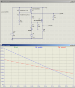
Here's an idea I had last night. Two MOSFETs, one to scale anode voltage (V_anode in the image), the other to scale screen voltage (V_screen).
Having the two voltages scale proportionally so that the screen voltage is always lower than the anode voltage is easy as pie. But I have some reason to believe that, in order to keep the load-line in the proper place wrt the "knee" of the curves, V_screen should start out below V_anode, but as V_anode is progressively lowered, V_screen should eventually become larger than V_anode.
Making that happen took some thought, but here it is. R3, D1, V5 are the key elements to making the two lines cross each other. When the voltage at the junction of R2 and R4 drops below V5, diode D1 starts to conduct, and R3 starts to flow current which changes the rate at which the screen voltage falls.
V5 would be a Zener diode or adjustable voltage reference in a real implementation of the circuit. In LTSpice, using a voltage source is much simpler.
-Gnobuddy
Attachments
Member
Joined 2009
Paid Member
- one person at a jam asked me if I was using a delay pedal, because you can actually hear the signal compress on the attack, and bounce back a fraction of a second later, as the screen voltage falls and then recovers. He heard that bounce-back and thought it was an echo from a delay pedal. So he was wondering where my invisible delay pedal was.
-Gnobuddy
this interests me a lot - do you know what were the details of the power supply and value of that screen resistor ?
Member
Joined 2009
Paid Member
Here's an idea I had last night. Two MOSFETs, one to scale anode voltage (V_anode in the image), the other to scale screen voltage (V_screen).
this looks like a worthwhile direction to explore
Maybe the sound will depend on other supply details - i.e. the 'output impedance' of the supply that you normally have in amps that you like the sound of verses the output impedance of the MOSFET - may need some series resistance / RC filter after the MSOFET to provide the right dynamic behaviour.
Not off the top of my head, but I still have the amp, so if I can't find my old hand-drawn schematics, I'll flip over the board and read the values for you.Do you know what were the details of the power supply and value of that screen resistor?
From my tinkering, both the screen resistor value, and the value of the screen bypass cap (screen grid to ground), contribute to the sound of the screen compression effect. I think the actual screen current drawn by the pentode, and the screen bypass cap value combine to set the attack time of the compressor. Meantime, the screen resistor and screen bypass cap set the decay / recovery time.
It may take me a day or two. Tonight is music jam night, so I won't be able to do this until tomorrow night after work.
-Gnobuddy
I hope so, too.
That said, IMO there was only one reply in this thread that could be taken as dismissive. Every other reply appears to me to have been a genuine attempt to help the OP.
Also IMO, several of those responses were good suggestions, including wiring outputs as triodes, using a MOSFET to implement power scaling, and using a speaker attenuator. All those are viable and proven ways to lower output power, each with its own advantages and disadvantages, like any engineering solution.
At any rate, I hope the OP gets the help he was looking for. He will not find an easier answer than "Build this speaker attenuator with two resistors", but perhaps he will find an answer more to his liking.
-Gnobuddy
Just seemed to turn away from his idea and sort of morphed into something else without any need of him.
One post from the OP, and he never came back, never a reply or thank you to the people who did respond to him. And at least the first ten posts in this thread were all pretty much direct responses to the OP's one and only post. After that, yes, it became clear to everyone that the OP had gone for good, so the thread morphed into something else.Just seemed to turn away from his idea and sort of morphed into something else without any need of him.
I don't think that was rude of us at all. If you start a conversation at a party and walk away, the conversation will naturally shift to other topics eventually.
Speaking of discourteous behaviour, I will add that if one asks for help from a group of strangers, and several of them take the trouble to give responses, it is nice to at least acknowledge the effort they made with a "Thank you!" Even if the answers weren't what one was hoping to hear. Walking away without a word is rude, IMO.
Back to pentode screen compression, I got home too late and too tired to take apart my little preamp last night. I'll try to get the component values for Bigun (and anyone else interested) tonight. B+ was around 140 volts DC, and I think the screen resistor was 270k or 330k, but I've completely forgotten the value of screen bypass cap, which is the other crucial part of the compressor time-constants.
The relatively low B+ for the pentode was a design choice; it was part of my strategy for keeping the voltage gain from the small-signal pentode relatively low, about the same as you'd get from a typical half-12AX7 triode gain stage.
-Gnobuddy
Member
Joined 2009
Paid Member
OP? - some people find themselves in over their heads pretty quickly on this forum. I believe there are many people who read-only, are not comfortable to dive in. When I was young and vulnerable (ha ha ha) I found the forum intimidating at first. The OP has made only 10 posts in 18 months.
One post from the OP, and he never came back, never a reply or thank you to the people who did respond to him. And at least the first ten posts in this thread were all pretty much direct responses to the OP's one and only post. After that, yes, it became clear to everyone that the OP had gone for good, so the thread morphed into something else.
I don't think that was rude of us at all. If you start a conversation at a party and walk away, the conversation will naturally shift to other topics eventually.
Speaking of discourteous behaviour, I will add that if one asks for help from a group of strangers, and several of them take the trouble to give responses, it is nice to at least acknowledge the effort they made with a "Thank you!" Even if the answers weren't what one was hoping to hear. Walking away without a word is rude, IMO.
Back to pentode screen compression, I got home too late and too tired to take apart my little preamp last night. I'll try to get the component values for Bigun (and anyone else interested) tonight. B+ was around 140 volts DC, and I think the screen resistor was 270k or 330k, but I've completely forgotten the value of screen bypass cap, which is the other crucial part of the compressor time-constants.
The relatively low B+ for the pentode was a design choice; it was part of my strategy for keeping the voltage gain from the small-signal pentode relatively low, about the same as you'd get from a typical half-12AX7 triode gain stage.
-Gnobuddy
Yes I agree, I think he should have at least said thank you and that he had something in mind and it did not seem to fit here some how. And I do like how we can take an idea and run with it (I am one guilty as charged) but that does not change my concern. I would like to have more people on here posting and am willing to look at what it is that would turn them away. Maybe we should have fleshed out what it was that he was seeking, maybe we hit him with too many options and in turn discounted his in the process? I don't know. I just want to see new blood here and do not want to scare any away.
When I was young and vulnerable (ha ha ha) I found the forum intimidating at first.
That is my concern. I do not know how to make it less so, maybe serve milk and cookies?
Member
Joined 2009
Paid Member
That is my concern. I do not know how to make it less so, maybe serve milk and cookies?
One option is a dedicated newbie forum in which helpful elmers can lurk, to provide a safe environment. But it would become a big drain on the Mods - maybe some Elmers could be deputized. More practically speaking, just let folk find their own comfort point as things work pretty good. Sometimes language and cultural differences are just too large and there’s no escaping the benefits of a thick skin and some humility.
Last edited:
I agree with you 100% on this. It has been quite sad to watch as the number of interesting threads in this particular sub-forum fell off a cliff in recent months. Comments by one of the moderators here, as well as the current state of ghost-town forums like AX84, suggest that this trend has been going on for maybe a couple of decades or more. There are fewer people interested in playing a musical instrument than there used to be, and even fewer interested in building electronics to go with them.I just want to see new blood here and do not want to scare any away.
I've been hoping that activity on this sub-forum will pick up again once winter arrives, and people start spending more time indoors. But I also worry that hobby electronics is ageing out in the same way that, say, stamp collecting, ham radio, and model railways already have.
Some trends are much bigger than us, and there may not be anything we can do to change that.
On a positive note, I think this thread turned out quite interesting, and brought out contributions from quite a few creative people.
-Gnobuddy
Personally, I feel there are already far too many sub-forums, dividing a dwindling number of participants into smaller and smaller pie-slices.One option is a dedicated newbie forum
A nuclear reactor needs a minimum critical mass of radioactive fuel to start generating lots of fast neutrons, and an electronics forum needs a minimum critical number of active members to start generating lots of interesting ideas.
Subdividing humanity into smaller and smaller comfort-zones seems to be what is happening globally as well, as we are all told to celebrate and emphasize as many trivial cultural differences as possible, instead of celebrating something vastly more important - our common humanity.
-Gnobuddy
I just took my 6JW8 preamp apart far enough to read most of the component values....do you know what were the details of the power supply and value of that screen resistor?
The 6JW8 is a triode and a pentode in the same nine-pin bottle, and this is the pentode section we're talking about.
B+ is 130V - 140V.
The screen resistor is 270k.
The screen bypass cap, from screen grid to ground, is 10nF, or what is usually called 0.01uF in North America, because of an inexplicable prejudice against the SI prefix "nano".
The anode resistor (load) is 47k.
The cathode resistor is 1.5k.
The cathode bypass cap is a 10uF electrolytic.
This pentode stage is part of the clean channel. The guitar signal first goes to the triode from the same 6JW8, then through a gain control, to the pentode.
The component values listed above work well for clean and mildly overdriven tones. But overdrive it too heavily, and it makes unpleasant blubbering sounds (blocking distortion.) That's why there is a separate drive channel.
As you turn up the gain control from zero, the pentode gradually starts to introduce some compression, and, as mentioned previously, at some settings, it's very clearly audible.
There's nothing special about the power supply itself, other than the rather low voltage. As mentioned previously, that is deliberate, as it helps to keep the voltage gain from the pentode under control. The rather low value of the pentode's anode load resistor is part of the same strategy.
-Gnobuddy
One post from the OP, and he never came back, never a reply or thank you to the people who did respond to him. And at least the first ten posts in this thread were all pretty much direct responses to the OP's one and only post. After that, yes, it became clear to everyone that the OP had gone for good, so the thread morphed into something else.
I don't think that was rude of us at all. If you start a conversation at a party and walk away, the conversation will naturally shift to other topics eventually.
Speaking of discourteous behaviour, I will add that if one asks for help from a group of strangers, and several of them take the trouble to give responses, it is nice to at least acknowledge the effort they made with a "Thank you!" Even if the answers weren't what one was hoping to hear. Walking away without a word is rude, IMO.
Back to pentode screen compression, I got home too late and too tired to take apart my little preamp last night. I'll try to get the component values for Bigun (and anyone else interested) tonight. B+ was around 140 volts DC, and I think the screen resistor was 270k or 330k, but I've completely forgotten the value of screen bypass cap, which is the other crucial part of the compressor time-constants.
The relatively low B+ for the pentode was a design choice; it was part of my strategy for keeping the voltage gain from the small-signal pentode relatively low, about the same as you'd get from a typical half-12AX7 triode gain stage.
-Gnobuddy
Hello!,
- Your responses are absolutely amazing. Super glad to learn from you all.
- The output transformer: I have two choices, 125CSE and 1760C, both from hammond. I am biased towards to 1760C (5W and half of the weight).
- The idea behind the amp is to cross the VOX ac15 preamp with a champ power section. I move the amp very often. Therefore light is definitely a concern. I want to make a light combo amp with a superb tone.
- I am also thinking about the power transformer. I would try with a hammond 290XEX (I do prefer the solid state rectification).
I am travelling during my first week of holidays. Apologies for my late replies.
Keep posting on any topic. 85% percent of my amp knowledge comes from this community.
- Status
- This old topic is closed. If you want to reopen this topic, contact a moderator using the "Report Post" button.
- Home
- Live Sound
- Instruments and Amps
- Vox AC15 EF86 with one power tube