With all that switching on the output of the transformer, you really need to put a 1000 ohm 3 watt resistor right on the output of the transformer. That way if a contact in a switch oxidizes in future & doesn't make contact, the transformer doesn't short a turn from excessive voltage.
Power Transformer
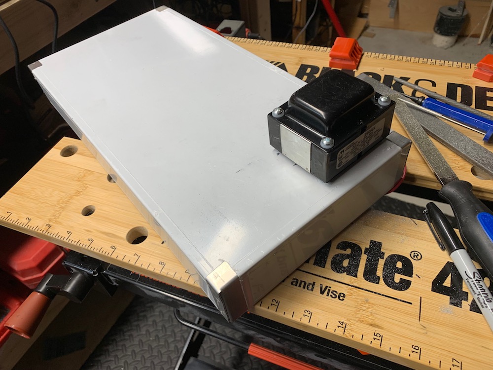
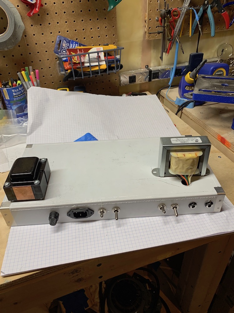
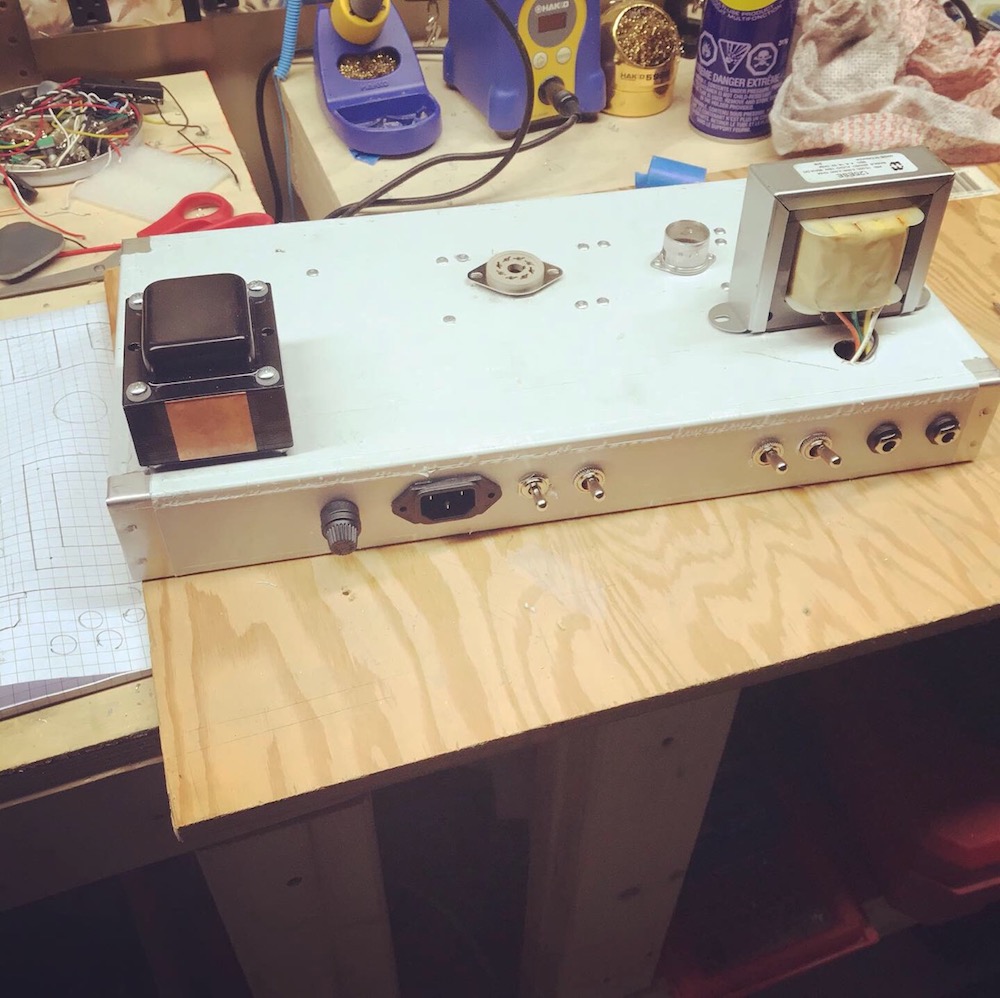
I knew where I wanted the power transformer - close to the back and to one side. This way it could be far away from sensitive components (i.e., input) and it would get support from being near two edges.
I practiced cutting the rectangle out on some scrap with a drill and fret saw.
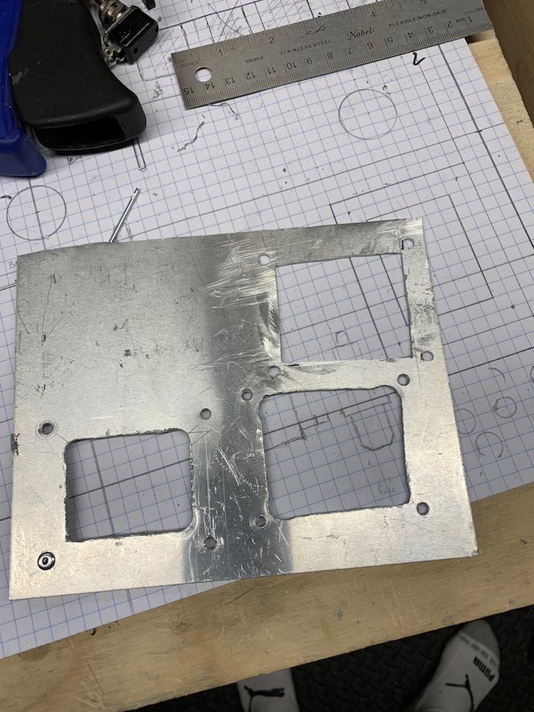
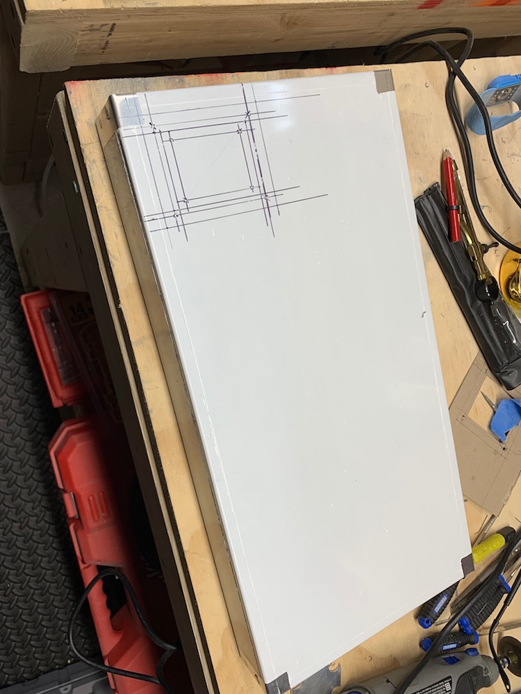
Then, using the transformer, I drew drilling guides on the chassis for the cut out and the mounting studs.
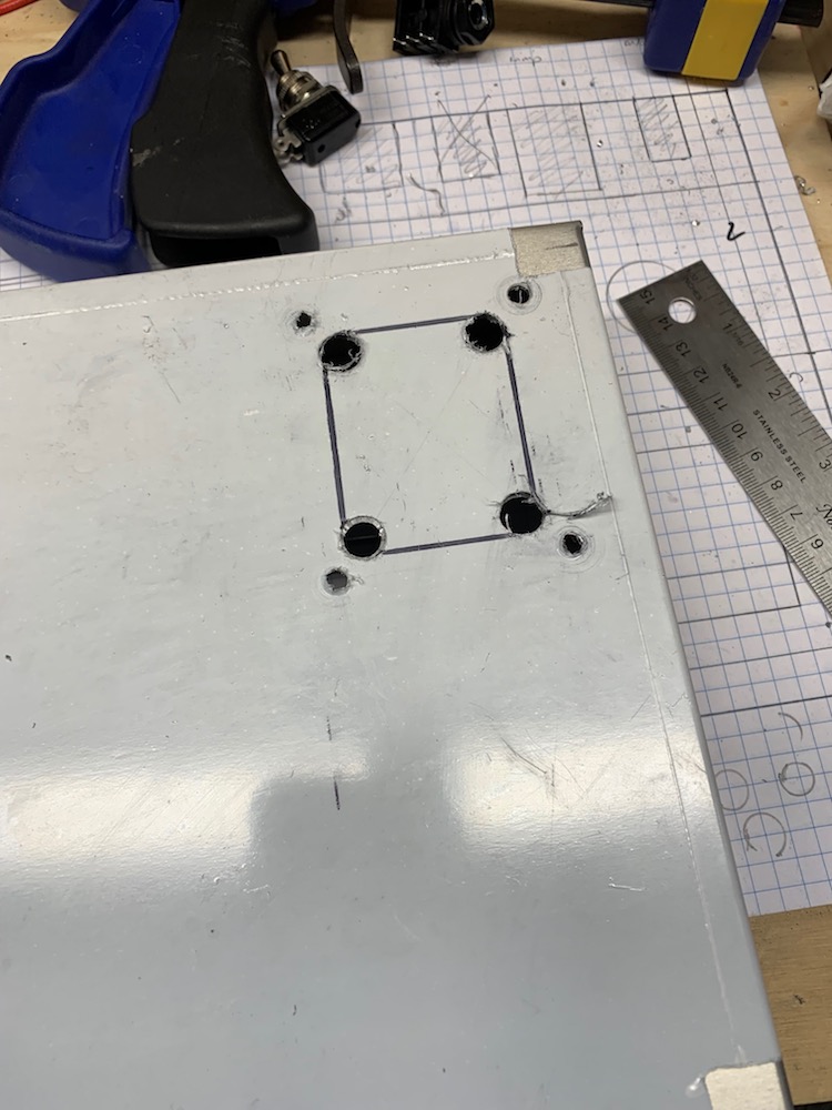
Using a step bit I drilled the larger cutout corners and drew lines to follow with the saw.
Using the saw I cut out the rectangle and later filed it smooth
Then I test fit the transformer.
I knew where I wanted the power transformer - close to the back and to one side. This way it could be far away from sensitive components (i.e., input) and it would get support from being near two edges.
I practiced cutting the rectangle out on some scrap with a drill and fret saw.
Then, using the transformer, I drew drilling guides on the chassis for the cut out and the mounting studs.
Using a step bit I drilled the larger cutout corners and drew lines to follow with the saw.
Using the saw I cut out the rectangle and later filed it smooth
Then I test fit the transformer.
Output Transformer
Positioning
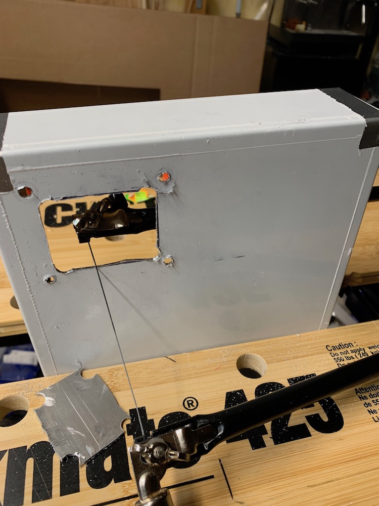
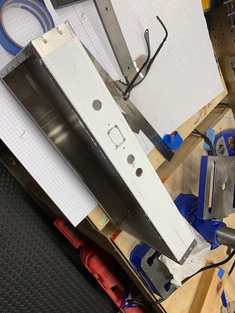
Although I was reasonably sure the opposite side of the chassis was the best place for the output transformer (in turms of noise and support) -- I figured it would interesting to try the headphone trick to check.
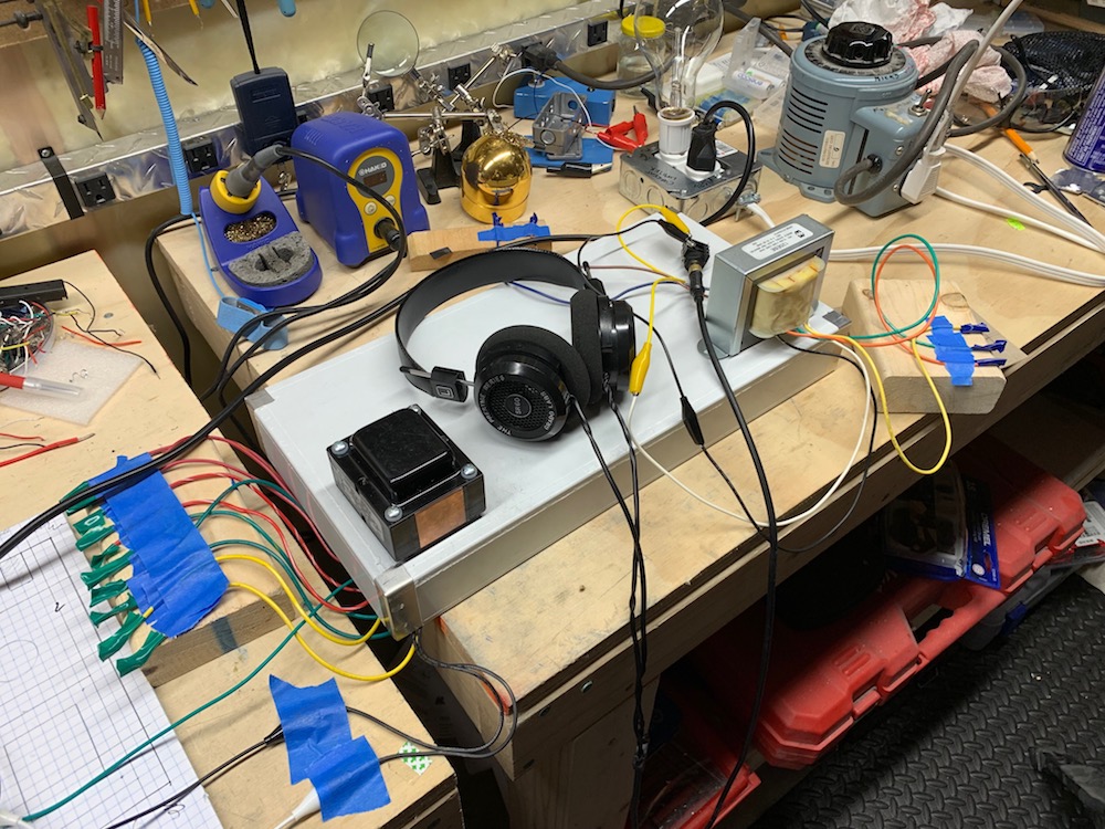
Here's the test setup
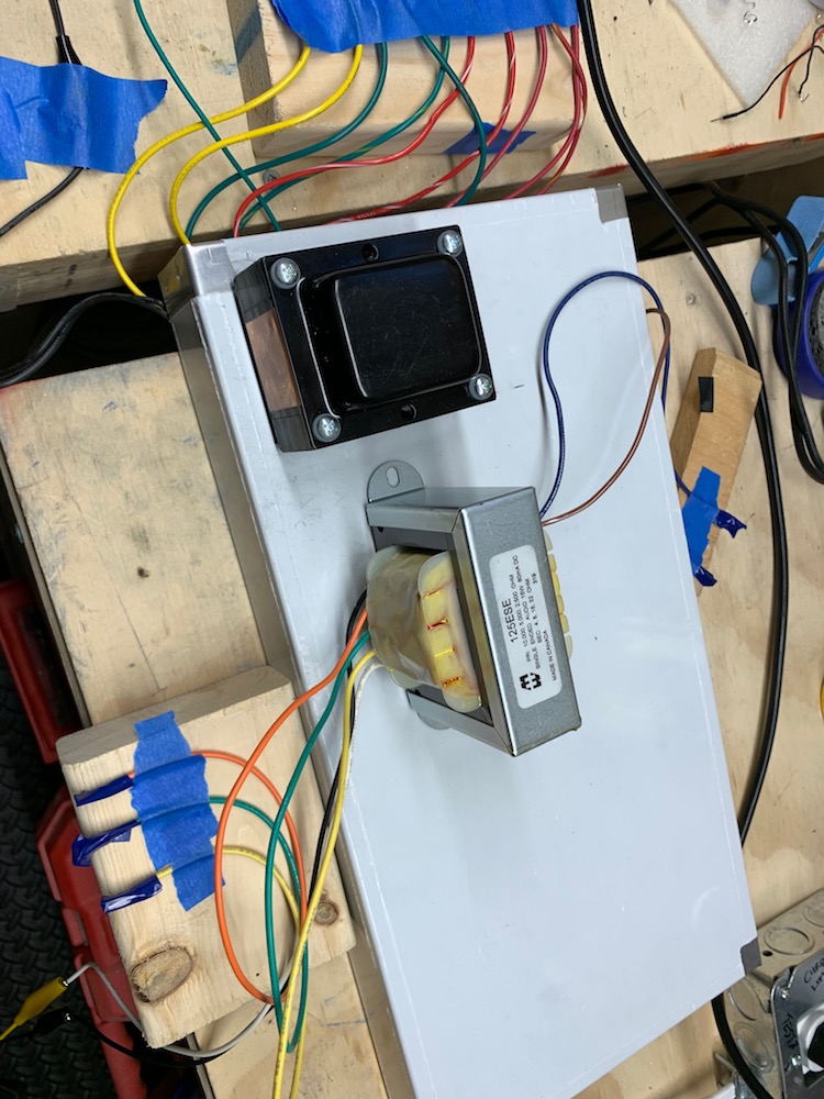
There was a lot of hum in this position
As expected, this position seemed to offer the least hum
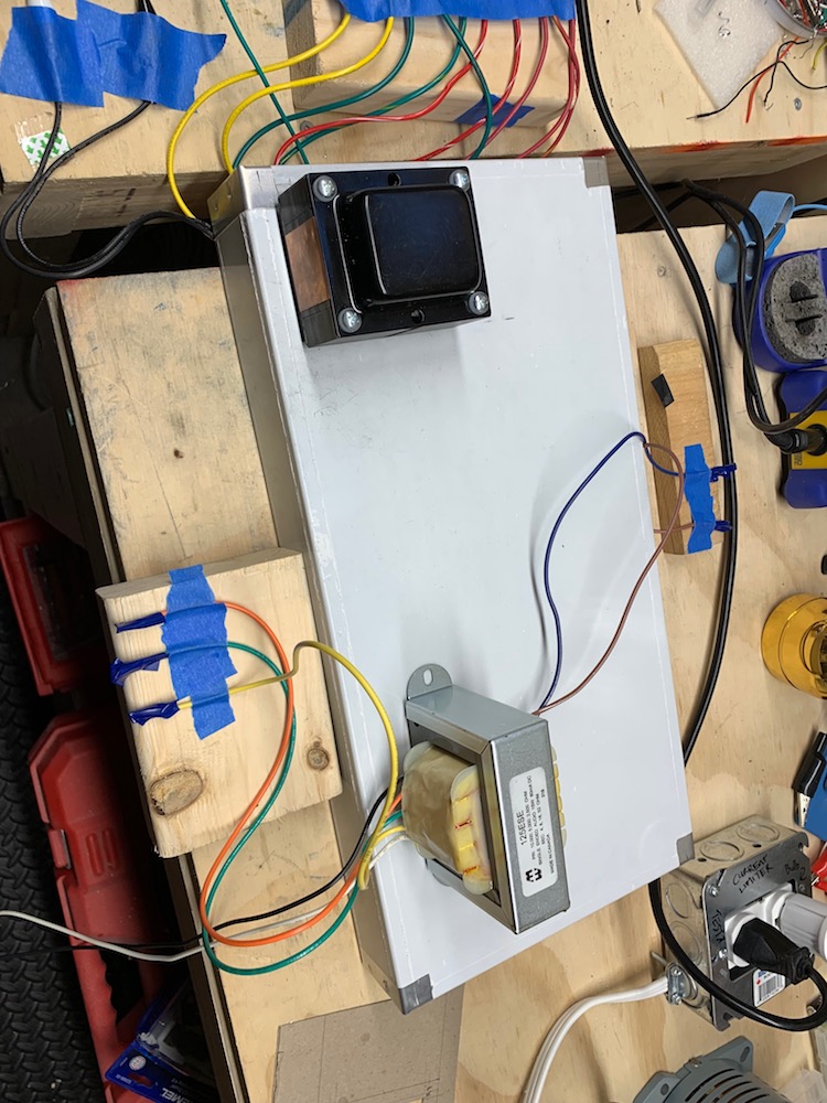
I tried various angles but this orientation and position seemed the best.
Positioning
Although I was reasonably sure the opposite side of the chassis was the best place for the output transformer (in turms of noise and support) -- I figured it would interesting to try the headphone trick to check.
- I taped off and tied down all the extra leads from the Power Transformer (PT) and the Output Transformer (OT).
- I jumpered in power to the PT's black leads.
- I jumpered in ¼ jack to the black and white leads of the OT.
- I pugged in my headphones to the ¼ jack.
- I plugged my variac into the wall. I made sure it was off and turned down.
- I plugged my current limiter into the variac.
- I plugged my OT into the current limiter.
- I turned on the variac and slowly brought the power up 120V.
- I started moving around the OT and listening to the different levels of hum depending on the proximity and orientation to the PT.
Here's the test setup
There was a lot of hum in this position
As expected, this position seemed to offer the least hum
I tried various angles but this orientation and position seemed the best.
Lots of progress, yay!
It would help a lot if you can down-size the pics before posting; they are much too big to see at present, unless you have an ultra-high-resolution screen. On my 21", full HD 1080p monitor, I can only see one corner of each photo at a time.
I typically resize pics to about 600 - 1000 pixels wide before posting to this forum, depending on how much detail I want people to be able to see.
-Gnobuddy
Back Panel
Hi/Lo Voltage Mod
new Mod-10 Hi/Low voltage switch
The Hammond 290AX has two secondary high voltage options: 325V and 275V.
In Episode 13 of Truth about Vintage Amps podcast, Skip mentions that the 275V option is useful for making an amp sound like an older Champ.
Back Panel Contents
With the amp in normal position, looking at the back, from left to right:
First I drew a horizontal centre line along the back.
Since I moved the Power Transformer close the back edge for support (see link), everything else had to scoot right.
The Output Transformer is not that close to the back edge so we still have lots of room for the speaker jacks.
The power outlet is another rectangle. This one was tricky to cut with the fret saw because it's close to the top of the chassis.
Here's the start of the layout:
Here is a test fit of the components so far:
Hi/Lo Voltage Mod
new Mod-10 Hi/Low voltage switch
The Hammond 290AX has two secondary high voltage options: 325V and 275V.
In Episode 13 of Truth about Vintage Amps podcast, Skip mentions that the 275V option is useful for making an amp sound like an older Champ.
Back Panel Contents
With the amp in normal position, looking at the back, from left to right:
- Fuse
- Power outlet
- 325V / 275V switch
- Tube / Solid-state rectifier switch
- Impedance switch 1
- Impedance switch 2
- Speaker jack 1
- Speaker jack 2
- Voltage Hi/Lo
- Rectifier Tube/Solid Stae
- Impedance selection
First I drew a horizontal centre line along the back.
Since I moved the Power Transformer close the back edge for support (see link), everything else had to scoot right.
The Output Transformer is not that close to the back edge so we still have lots of room for the speaker jacks.
The power outlet is another rectangle. This one was tricky to cut with the fret saw because it's close to the top of the chassis.
Here's the start of the layout:
Here is a test fit of the components so far:
Revised Schematic, Layout and Mock up
Mods Status
Mod-1. Added a 470Ω screen resistor to V2 (see forum discussion), .
Mod-2. Added some SPDT switches to pick 3 of the 4 output transformer impedances.
Mod-3. Change R4, the 68KΩ grid stopper on V1. I used the Merlin suggested 10KΩ + 680pF capacitor.
Mod-4. Variable negative feedback
Mod-5. Presence control.
Mod-6. Switchable Solid State Rectifier.
pending Mod-7. @mhammer also suggested a neat mod where instead of voicing switch you replace it with a W-Taper hooked up to the 2 bypass caps so you could vary the amount of bypass.
I don't have the pot now, but there should be plenty of room to replace the switch in the future.
new Mod-8 Safety load on OT
With all that switching on the output of the transformer, you really need to put a 1000 ohm 3 watt resistor right on the output of the transformer. That way if a contact in a switch oxidizes in future & doesn't make contact, the transformer doesn't short a turn from excessive voltage.
(from indianajo)
new Mod-9 Second cathode bypass
I would add a 25uF switchable cathode bypass to V1B for a 5E3 position.
(from RobRob)
new Mod-10 Hi/Low voltage switch
The Hammond 290AX has two secondary high voltage options: 325V and 275V.
In Episode 13 of Truth about Vintage Amps podcast, Skip mentions that the 275V option is useful for making an amp sound like an older Champ.
Back Panel Switch note: All of the back panel switches should only be changed while the amp is off
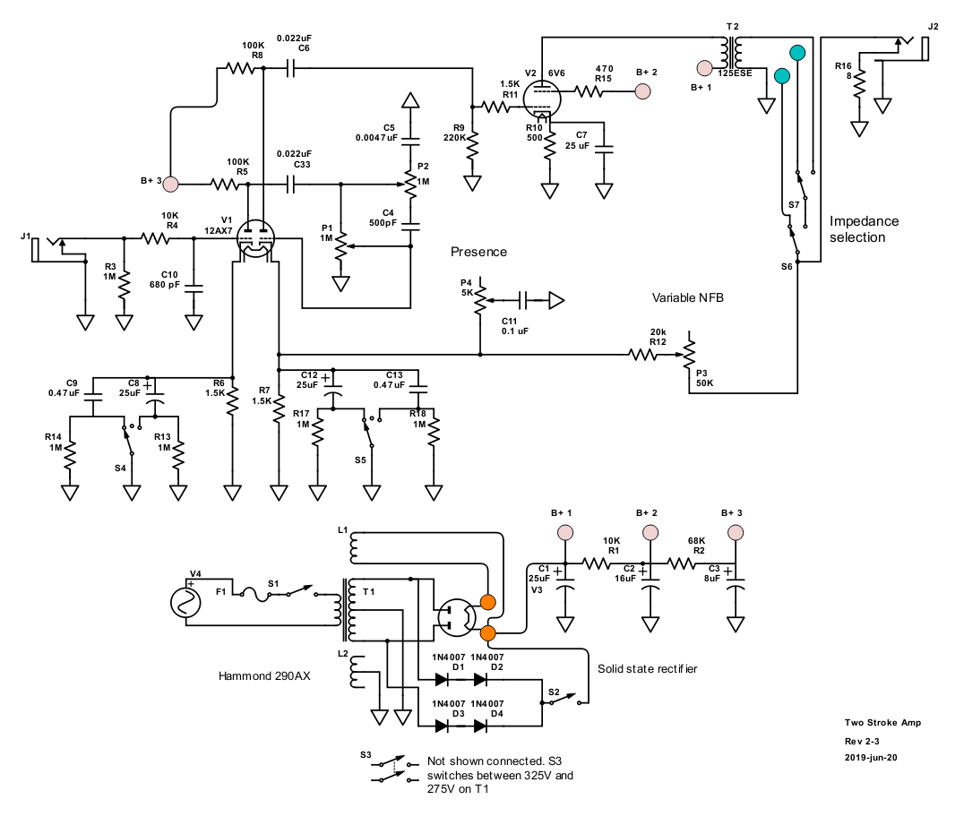
Revised Schematic - Rev 2-3
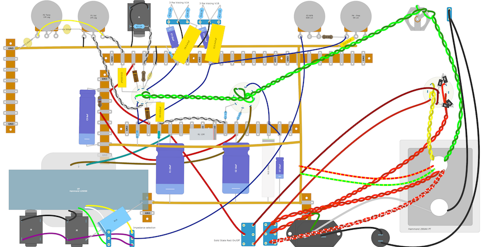
Revised DIY Layout
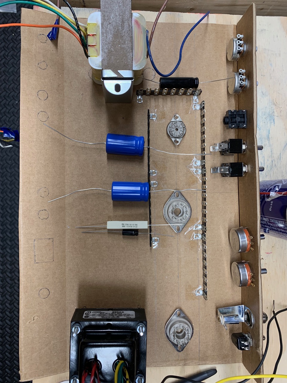
Cardboard Mock Ups
Before drilling wth front panel, tube sockets and terminal holes I started mocking up the amp in cardboard.
Based on previous picture RobRob mentioned that although the output transformer was isolated from the power transformer, it was now close to V1. Based on the mock ups, I think it will be ok because:
its off to the side of the OT (although Morgan Jones does say that there is more leakage at the corners of the core)
I plan on using a shielded V1
I plan on using shield cable for the signal
Slight angle, looking from back to front
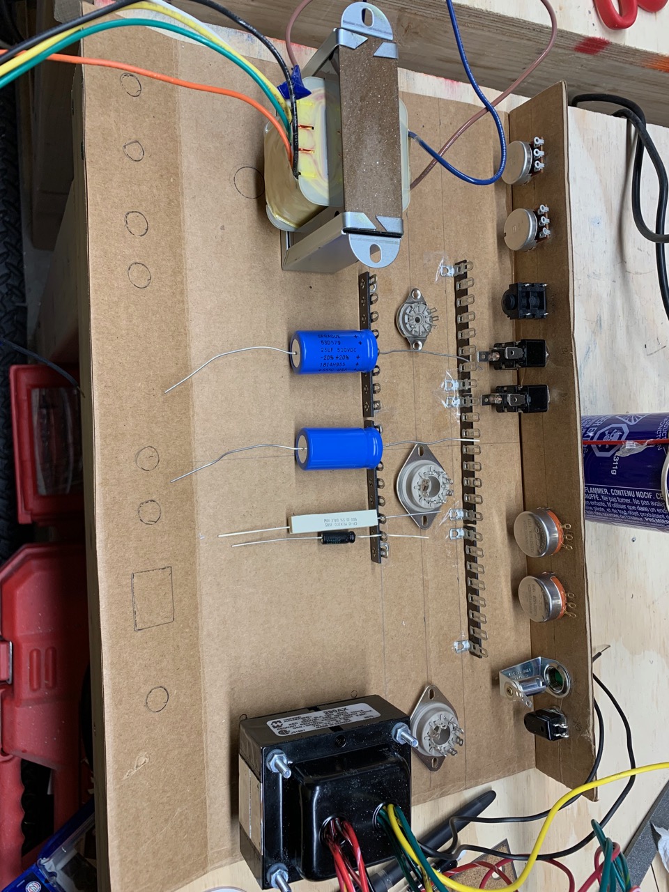
Top down
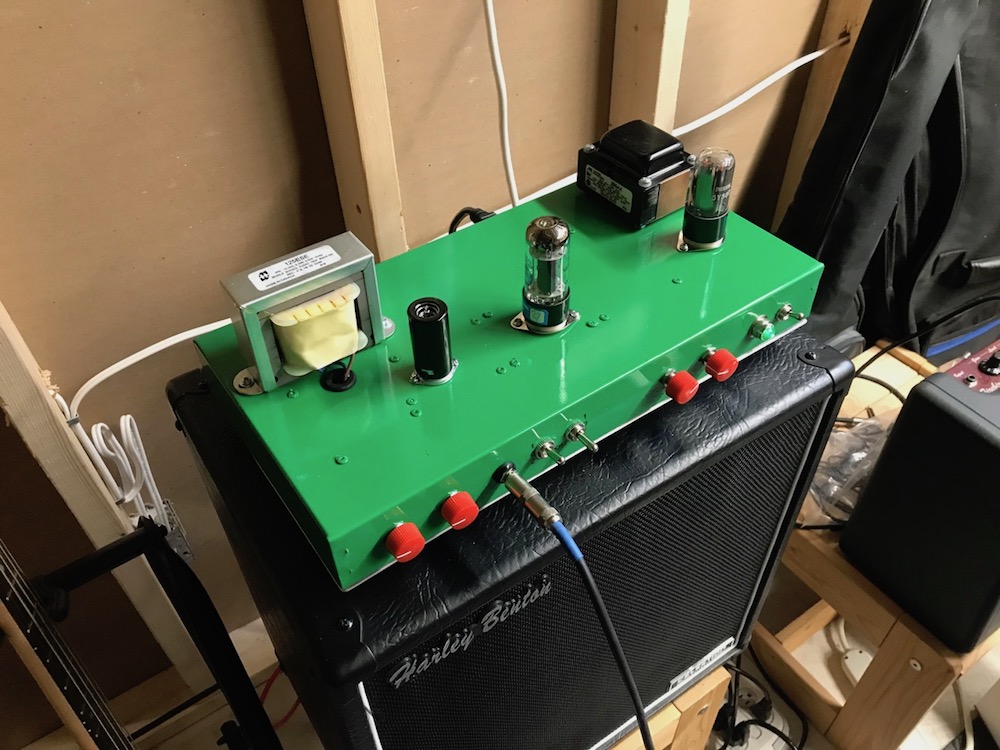
Tubes + Transformers
Laying out the tube sockets on top with the transformers (and using the approximate measurements from the mock up) I see something like this:
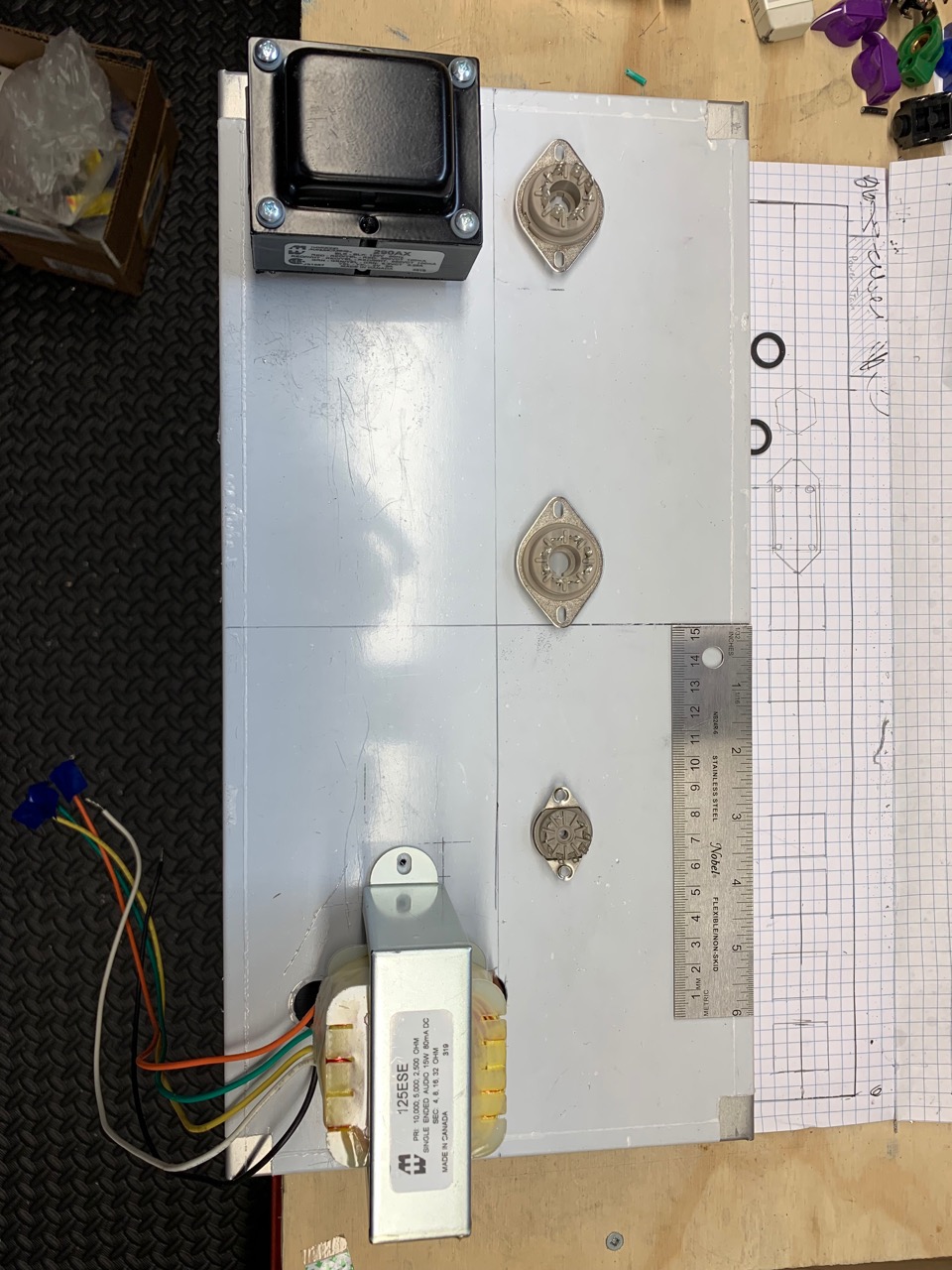
Some thoughts:
Mods Status
Mod-1. Added a 470Ω screen resistor to V2 (see forum discussion), .
Mod-2. Added some SPDT switches to pick 3 of the 4 output transformer impedances.
Mod-3. Change R4, the 68KΩ grid stopper on V1. I used the Merlin suggested 10KΩ + 680pF capacitor.
Mod-4. Variable negative feedback
Mod-5. Presence control.
This was suggested by @mhammer and by watching Uncle Doug: NFB and Presence.
I combined the two. If I understand correctly, the first pot controls the amount negative feedback, and the second will decide how much of the frequency gets rolled off.
I combined the two. If I understand correctly, the first pot controls the amount negative feedback, and the second will decide how much of the frequency gets rolled off.
Mod-6. Switchable Solid State Rectifier.
I saw this in a post and post on the Tube Amp Network.pending Mod-7. @mhammer also suggested a neat mod where instead of voicing switch you replace it with a W-Taper hooked up to the 2 bypass caps so you could vary the amount of bypass.
I don't have the pot now, but there should be plenty of room to replace the switch in the future.
new Mod-8 Safety load on OT
With all that switching on the output of the transformer, you really need to put a 1000 ohm 3 watt resistor right on the output of the transformer. That way if a contact in a switch oxidizes in future & doesn't make contact, the transformer doesn't short a turn from excessive voltage.
(from indianajo)
new Mod-9 Second cathode bypass
I would add a 25uF switchable cathode bypass to V1B for a 5E3 position.
(from RobRob)
new Mod-10 Hi/Low voltage switch
The Hammond 290AX has two secondary high voltage options: 325V and 275V.
In Episode 13 of Truth about Vintage Amps podcast, Skip mentions that the 275V option is useful for making an amp sound like an older Champ.
Back Panel Switch note: All of the back panel switches should only be changed while the amp is off
- Voltage Hi/Lo
- Rectifier Tube/Solid Stae
- Impedance selection
Revised Schematic - Rev 2-3
Revised DIY Layout
Cardboard Mock Ups
Before drilling wth front panel, tube sockets and terminal holes I started mocking up the amp in cardboard.
Based on previous picture RobRob mentioned that although the output transformer was isolated from the power transformer, it was now close to V1. Based on the mock ups, I think it will be ok because:
its off to the side of the OT (although Morgan Jones does say that there is more leakage at the corners of the core)
I plan on using a shielded V1
I plan on using shield cable for the signal
Slight angle, looking from back to front
Top down
Tubes + Transformers
Laying out the tube sockets on top with the transformers (and using the approximate measurements from the mock up) I see something like this:
Some thoughts:
- I could go with the current layout and see what happens.
- I might be able to move the tubes about ½ inch closer to the front of the chassis (right now the tube centre line is 3 inches from the front).
- I could plug the existing holes for the OT and move it towards the PT. I could also move V1 as close as possible to right side of the chassis. I don't know if this will make much difference unless I move the OT very close to the PT. As JunoMike and OldJoat suggested I could look at making shield.
I'm kind of late to the thread, but John Hynes's Gothik Ring approach is worth considering for this type of build.
http://geckoamps.com/P1-Gothik-Ring-Layout/p1-gothik-ring.pdf
Stph
http://geckoamps.com/P1-Gothik-Ring-Layout/p1-gothik-ring.pdf
Stph
but John Hynes's Gothik Ring approach is worth considering for this type of build.
http://geckoamps.com/P1-Gothik-Ring-Layout/p1-gothik-ring.pdf
Stph
Awesome. It took me a bit to realize they were can caps.
That article lead me to the HyTronix site. Lots of good reading -- and timely!
+1C8 C12 will leak. Especially with age and heat. R13 R17 can be smaller to absorb better. If made 15K the effect when "open" would be very slight, so say 33k or 47k.
but you may get by if your caps are in good condition with 100k-ish pulldowns.
Test fit, prime and paint
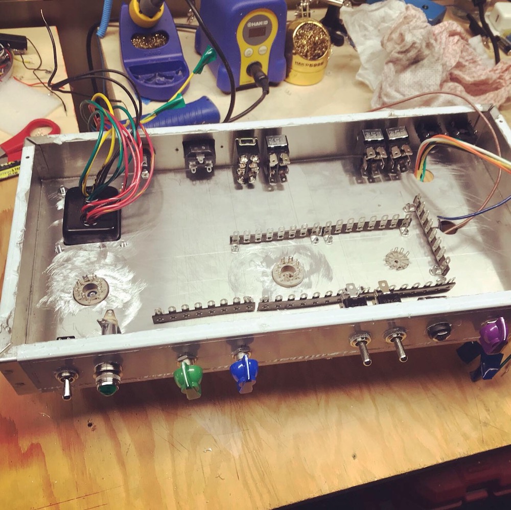
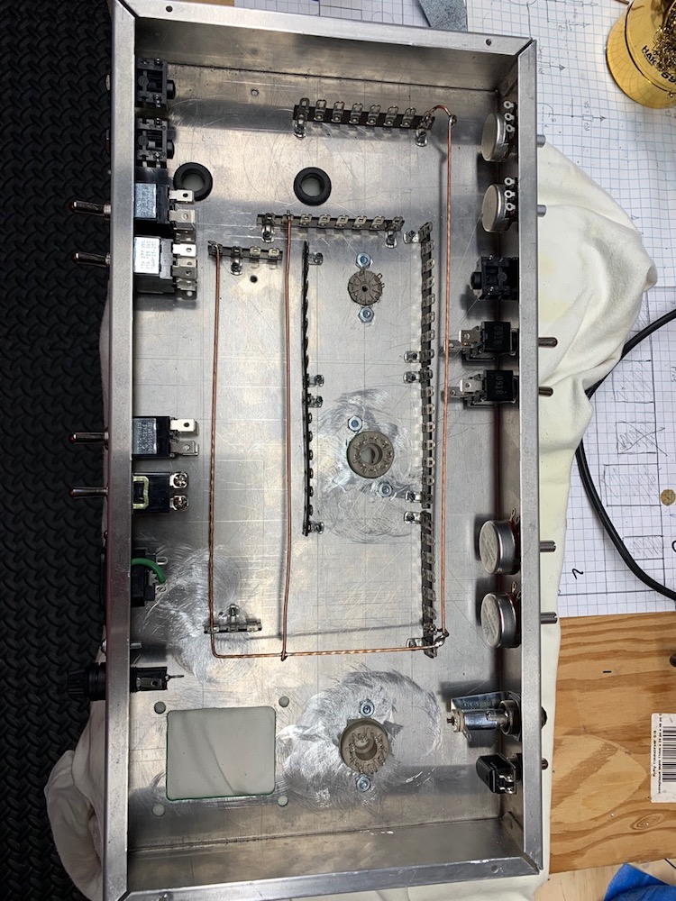
Test fitting the components into the chassis:
Front view
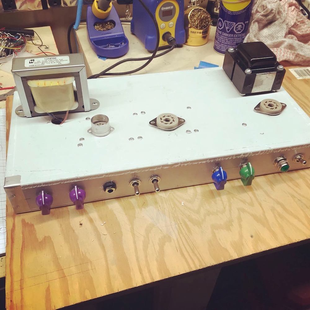
Back view
Inside view
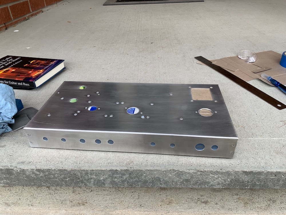
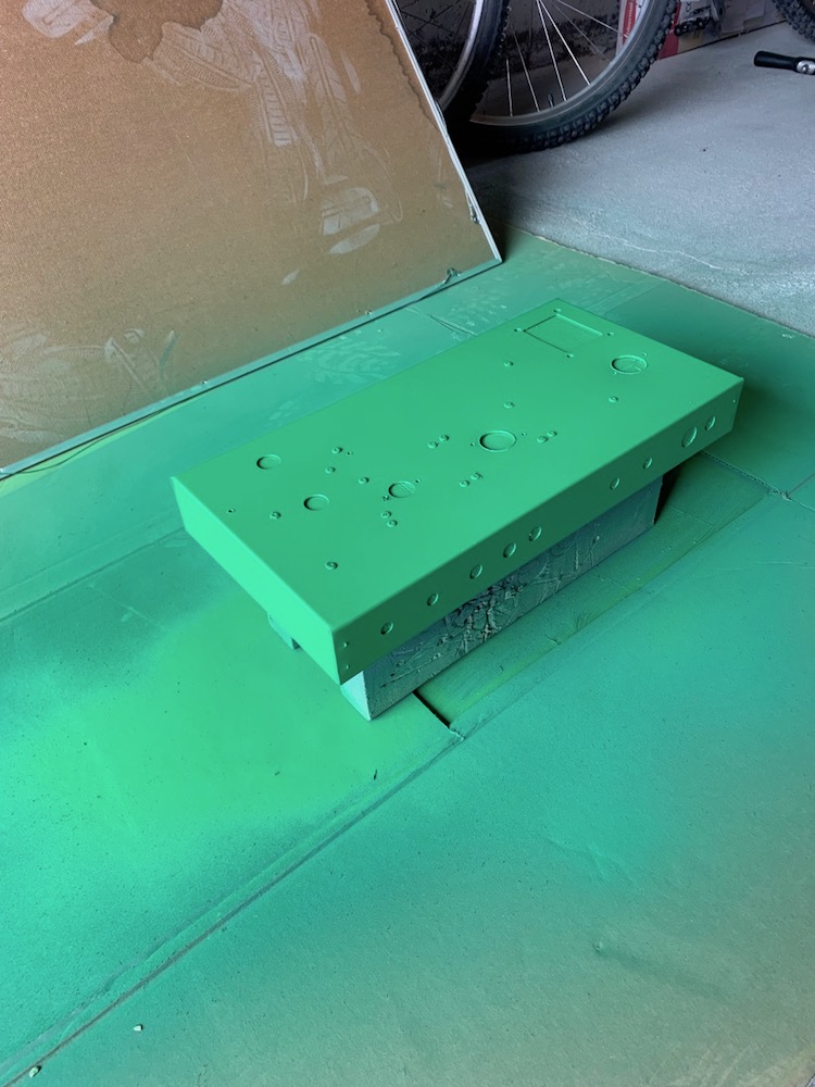
Removed the film, lightly buffed, rinsed with acetone, ready to prime
Primed (2-3 coats). Earlier I primed and painted the bottom plate as a test piece to get used the paint and primer.
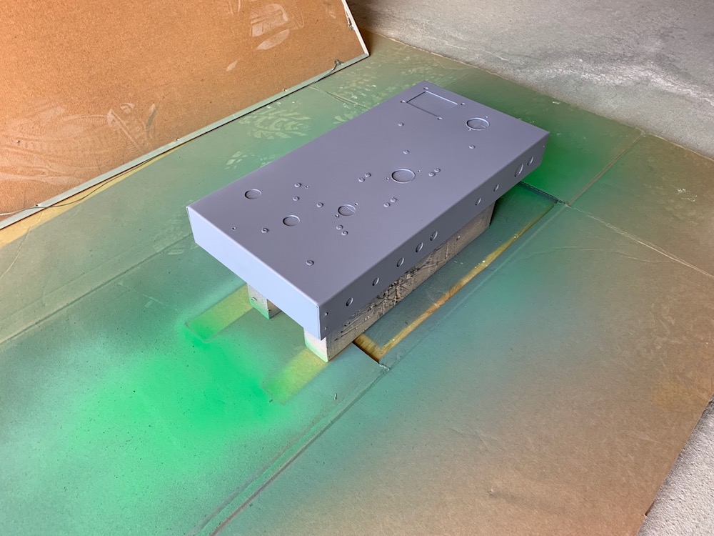
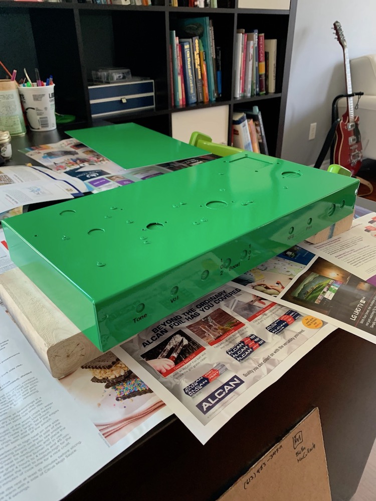
And one day later, painted (3 coats, about 5-7 minutes apart)
Test fitting the components into the chassis:
Front view
Back view
Inside view
Removed the film, lightly buffed, rinsed with acetone, ready to prime
Primed (2-3 coats). Earlier I primed and painted the bottom plate as a test piece to get used the paint and primer.
And one day later, painted (3 coats, about 5-7 minutes apart)
Label, Clear Coat, and Grounding
I used Rub-on Dry Transfer letters to label the amp and then applied several coats of clear in one session, a few minutes in between coats:
After letting the clear coat cure for 24 hours I bolted on the fixtures.
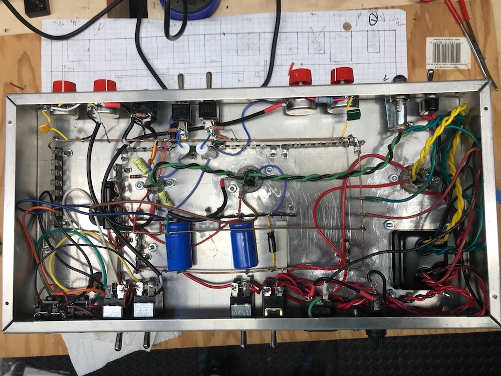
Next, using the technique from Blueglow Electronics I made the grounding bus and attached it:
I used Rub-on Dry Transfer letters to label the amp and then applied several coats of clear in one session, a few minutes in between coats:
After letting the clear coat cure for 24 hours I bolted on the fixtures.
Next, using the technique from Blueglow Electronics I made the grounding bus and attached it:
C8 C12 will leak. Especially with age and heat. R13 R17 can be smaller to absorb better. If made 15K the effect when "open" would be very slight, so say 33k or 47k.
+1
but you may get by if your caps are in good condition with 100k-ish pulldowns.
I am not following.
If I understand correctly,
C8 and C12 cathode bypass capacitors are more prone to leaking voltage because they are electrolytic capacitors.
R13 and R17, the 1M anti-popping / pull down resistors are too big. Since the resistors were not in the original design (they were added by the Tube Amp Network folks) I might leave them out and see what it sounds like.
Regardless, I am curious how would calculate an appropriate value for a given capacitor.
Thanks
Oooh! Can you please tell me where you bought them?I used Rub-on Dry Transfer letters to label the amp
I used to use Letraset rub-down transfer letters for exactly this purpose in the 1980s, but I have been unable to find them in recent decades. I thought they were gone for good, particularly after numerous 'Web searches turned up nothing.
-Gnobuddy
Oooh! Can you please tell me where you bought them?
I used to use Letraset rub-down transfer letters for exactly this purpose in the 1980s, but I have been unable to find them in recent decades. I thought they were gone for good, particularly after numerous 'Web searches turned up nothing.
-Gnobuddy
Staples HeadLine Rub On Lettering 3/16" | Staples(R) - Staples.ca
HeadLine Rub On Letters and Numbers
Thanks! Much appreciated.
-Gnobuddy
6V6 Voltages
Power Transformer :
Output Transformer
Output Tube
Hunter’s books suggests:
V2 Cathode resistor: 494.7 ohms
I can run the amp in 325V or 275 V.
I can run use the tube rectifier or diode rectifier.
Calculated cathode current: measured-voltage / cathode resistor
Calculated plate dissipation: calculated-current * measured plate voltage
Here are the combinations ordered in descending voltage
Combo 1: 325 V + Diode Rect
Combo 2: 325 V + Tube Rect
Combo 3: 275 V + Diode Rect
Combo 4: 275 V + Tube Rect
If I did these measurement right and if I am interpreting them correctly, I should only run the amp with this 6V6 in combo 3 or 4.
Combo 2 might be ok, but combo 1 seems too high.
Does this make sense?
Do any of these numbers look suspicious?
What other measurements should I do?
Power Transformer :
Output Transformer
Output Tube
6V6EH (https://www.thetubestore.com/lib/thetubestore/eh-6v6eh.pdf)
Max plate dissipation: 14W
Max plate voltage: 450V
Cathode Current: 80mA
Max plate dissipation: 14W
Max plate voltage: 450V
Cathode Current: 80mA
Hunter’s books suggests:
340-360 VDC on the plate, not beyond 380
300 VDC on the screen, not above 350
300 VDC on the screen, not above 350
V2 Cathode resistor: 494.7 ohms
I can run the amp in 325V or 275 V.
I can run use the tube rectifier or diode rectifier.
Calculated cathode current: measured-voltage / cathode resistor
Calculated plate dissipation: calculated-current * measured plate voltage
Here are the combinations ordered in descending voltage
Combo 1: 325 V + Diode Rect
Measurements:
Calculations:
@ C1: 436.7 VDC
@ C2: 378.0 VDC
@ C3: 265.6 VDC
Cathode resistor voltage: 21.95 VDC
V2 plate to ground: 402.6 VDC
V2 screen to ground: 376.7 VDC
V2 plate to cathode: 376.30 VDC
@ C2: 378.0 VDC
@ C3: 265.6 VDC
Cathode resistor voltage: 21.95 VDC
V2 plate to ground: 402.6 VDC
V2 screen to ground: 376.7 VDC
V2 plate to cathode: 376.30 VDC
Calculations:
cathode current: 44.4 mA
plate dissipation (plate-ground): 17.86 W
plate dissipation (plate-cathode): 16.70 W
plate dissipation (plate-ground): 17.86 W
plate dissipation (plate-cathode): 16.70 W
Combo 2: 325 V + Tube Rect
Measurements:
@ C1: 399.0 VDC
@ C2: 245.0 VDC
@ C3: 244.0 VDC
Cathode resistor voltage: 20.20 VDC
V2 plate to ground: 372.0 VDC
V2 screen to ground: 344.3 VDC
V2 plate to cathode: 347.50 VDC
Calculations@ C2: 245.0 VDC
@ C3: 244.0 VDC
Cathode resistor voltage: 20.20 VDC
V2 plate to ground: 372.0 VDC
V2 screen to ground: 344.3 VDC
V2 plate to cathode: 347.50 VDC
Calculated cathode current: 40.8 mA
Calculated plate dissipation (plate-ground): 15.19
Calculated plate dissipation (plate-cathode): 14.19
Calculated plate dissipation (plate-ground): 15.19
Calculated plate dissipation (plate-cathode): 14.19
Combo 3: 275 V + Diode Rect
Measurements
@ C1 376.80 VDC
@ C2 327.20 VDC
@ C3 231.20 VDC
Cathode resistor voltage: 19.02 VDC
V2 plate to ground: 352 VDC
V2 screen to ground: 326.2 VDC
V2 plate to cathode: 329.0 VDC
Calcultations@ C2 327.20 VDC
@ C3 231.20 VDC
Cathode resistor voltage: 19.02 VDC
V2 plate to ground: 352 VDC
V2 screen to ground: 326.2 VDC
V2 plate to cathode: 329.0 VDC
Calculated cathode current: 38.4 mA
Calculated plate dissipation (plate-ground): 13.55 W
Calculated plate dissipation (plate-cathode): 12.65 W
Calculated plate dissipation (plate-ground): 13.55 W
Calculated plate dissipation (plate-cathode): 12.65 W
Combo 4: 275 V + Tube Rect
Measurements:
@ C1: 340.0 VDC
@ C2: 296.3 VDC
@ C3: 209.70 VDC
Cathode resistor voltage: 18.1 VDC
V2 plate to ground: 321.5 VDC
V2 screen to ground: 294.5 VDC
V2 plate to cathode: 300.20
Calculations@ C2: 296.3 VDC
@ C3: 209.70 VDC
Cathode resistor voltage: 18.1 VDC
V2 plate to ground: 321.5 VDC
V2 screen to ground: 294.5 VDC
V2 plate to cathode: 300.20
Calculated cathode current: 36.6 ma
Calculated plate dissipation (plate-ground): 11.76 W
Calculated plate dissipation (plate-cathode): 10.98 W
Calculated plate dissipation (plate-ground): 11.76 W
Calculated plate dissipation (plate-cathode): 10.98 W
If I did these measurement right and if I am interpreting them correctly, I should only run the amp with this 6V6 in combo 3 or 4.
Combo 2 might be ok, but combo 1 seems too high.
Does this make sense?
Do any of these numbers look suspicious?
What other measurements should I do?
- Status
- This old topic is closed. If you want to reopen this topic, contact a moderator using the "Report Post" button.
- Home
- Live Sound
- Instruments and Amps
- First crack at P2P layout