The Zout is really the impedance you see when you 'look back' into the output.
So what do you see then? If you have no load on the output, you 'see' the impedance of the circuit itself, like a triode with an anode resistor.
What is the impedance you see when you look at that anode, which normally is the output? You have to ask: if I insert a signal at the output, where can it go? Two paths, at least: the anode resistor Ra,because for signals B+ is ground, and into the anode itself*, which represents the internal tube impedance Ri. So the output impedance you see is Ri in parallel with Ra. For instance, if Ri is 8k and Ra is 16k (just made-up numbers), the Zout is 8k // 16k = about 5.3k.
Now you put a load resistor of 1k on the output. What do you see now when looking into the output? Still the original 5.3k, that hasn't changed, but also, in parallel with that, this new 1k. So now you made Zout = 5.3k // 1k = about 840 ohms.
That why I said before, to measure Zout can be done by inserting a current into the output, with a grounded input, and measuring Vout. Ohms law gives you Zout = Vout/Iinsert.
Jan
* ending up eventually at ground through the cathode
Last edited:
If you are equipment-challenged, there is a simple method to measure Zout for a specific frequency. It is based on the understanding that if you draw output current through a load, the signal will drop because Zout and the load will form a voltage divider.
What you do is measure Vout with no load and then connect progressively lower load resistors until Vout has dropped to half the unloaded value. At this point you know that half of the original voltage is across Zout, and the other half across the load. So Zout = Rload.
The intriguing thing is that in all this you can treat Zout as if it is a physical resistance (or impedance), although there isn't any specific component you can point at and say: 'that component is Zout'. It is a result of how the circuit reacts to load.
Going further (advance warning): at higher frequencies many circuit amplification properties become smaller. That means that the Zout will increase with higher frequencies. Errr ... there's a part that has an increase in impedance with frequency, right, we call it 'inductor'.
What do you know, the upshot is that with rising frequency the amplifier's Zout starts to look like an inductor! Even when there is no physical coil anywhere in the circuit, it is so real that with a suitable capacitance it can oscillate!
Jan
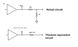
I am confused by the fact that in real circuit Zout is going down when the output signal is pulled to ground.
The resistor that you use to reduce the output voltage, is the reason that the net output impedance
reduces. The reduced output impedance results from the effect of the 3k resistor shunting the output.
If the 3k were in series, Zout would get larger, but since the 3k is connected in shunt, Zout gets smaller.
However, most circuits should not be heavily loaded, and their (unloaded) output impedance must be
much smaller than the load resistance that is connected to them.
Attachments
Last edited:
...confused by the fact that in real circuit Zout is going down when the output signal is pulled to ground. Which is not a good thing for a signal, right?
If the signal is Too Strong, then reducing it may be A Good Thing.
Remember there are normal people, and electric guitarists. Normal people only amplify as much as they need. E-guitarists will throw in 2 3 even 4 extra stages of tubes so the signal is distorted (to add musical emphasis on unexpressive steel strings). With tubes you can have 100 Volts of signal! Any power amp will be saturated with 1V-2V. So the usual technique IS to boost to HUGE level, then pad it down for a happy level the power amp can swallow.
I have seen an unpublished work, general info but explained carefully, which goes into this. The output of a HARD-clipped 290V tube stage can feed a 820k:10k pad to come out at "effect level" (pedals can swallow it) and Zout is under 10K so it will feed "any" pedalboard load or most studio effects.
On stage, 10k is a fine low impedance. In a larger world you may want lower. Feeding 1,000' to a distant mix-board you want <500r. Feeding multiple recorders (I used to do this on live concerts) you may want a to feed a dozen 10k loads with 1dB consistency, which means <100r. But that's not the guitar amp's job: I built a "Distribution Amplifier" with a whole lot of jacks and isolation resistors (a few transformers for remote lines).
But I am confused by the fact that in real circuit Zout is going down when the output signal is pulled to ground.
When you 'pull it to ground', you put a resistor from output to ground. This resistor is now in parallel with the original Zout, so naturally the parallel of the two is lower than the original. It has nothing to do with the actual signal level.
The drawing in post # 23 above shows this.
Jan
I'm still not hapopy with my explanation for someone who is new to this.
Let me try once more.
What is 'output impedance'? It is the impedance you 'see' when looking into the output. What you see is a number of signal paths to ground, and the 'size' of these path in ohms determines the impedance you see.
So what paths do you see (assume the output is from the anode). You see the anode resistor, because it has a path to ground (via the power supply capacitors). You also see the tube internal Ri because it has a path to ground, via the cathode.
If you put 1k at the output to ground, that is a third path to ground.
Since all these paths are in parallel, the effective impedance is the parallel value of all these paths.
In the example given above, say Ra = 8k, Ri = 16k and Rload is 1k, the effective parallel Zout is 840 ohms.
Does that make sense?
Jan
Last edited:
Post 6 also shows the meaning of output impedance, which is what you are asking about.i3alan said:The post #6 shows one of the ways to calculate the output Z.
You need to learn about Ohm's law, potential dividers, and resistances in series and parallel. There is no point in measuring an output impedance until you first understand what an output impedance is.
You need to think about what is the circuit you are measuring. Does it include the 3k3 resistor, or is that an external load on the circuit? There is not a right answer to this question, as it is your circuit so you can decide. You just need to be consistent.But I am confused by the fact that in real circuit Zout is going down when the output signal is pulled to ground.
You need to think about what is the circuit you are measuring. Does it include the 3k3 resistor, or is that an external load on the circuit? There is not a right answer to this question, as it is your circuit so you can decide. You just need to be consistent.
That is a good point. If the 3.3k is part of the preamp, and if the connection is downstream to the load from there, it is reasonable to consider the 3.3k as part of the preamp and thus as part of the Zout.
If the 3.3k is NOT in the preamp but on the other side of the cable at the load, it is reasonable NOT to consider it part of Zout, but part of the load.
Jan
No matter how you set your controls or what you drive them with, you **ALWAYS** have 3k3 in parallel with the output connector/cable so your outoput impedance IS 3k3 in parallel with the generator impedance.
In this case the generator is the Preamp and its output impedance is high, (what was calculated above by others) so your output impedance, the one which is driving the output cable and the load at the other end, IS "a little less than 3k3".
Don´t overthink it.
In this case the generator is the Preamp and its output impedance is high, (what was calculated above by others) so your output impedance, the one which is driving the output cable and the load at the other end, IS "a little less than 3k3".
Don´t overthink it.
Start with a set of triode curves, and explain the concept of plate resistance, rp. Without understanding rp, how can anybody understand Output Impedance of a single ended triode amp stage? Paralleling the plate load resistor with rp does not make sense to someone who does not know what rp is.
Thanks everybody for the great info!
I understand how to analyze the output impedance of the triode gain stage, that's not a problem.
I think I am starting to get a grasp on my initial question.
I understand how to analyze the output impedance of the triode gain stage, that's not a problem.
- Makes total sense.In the example given above, say Ra = 8k, Ri = 16k and Rload is 1k, the effective parallel Zout is 840 ohms.
Does that make sense?
I think I am starting to get a grasp on my initial question.
So is it correct to say that in order to feed a low input impedance load (10K) we should amplify a source signal to the very high level and then pad it down getting a very low output impedance (100R)? And another way to lower the output impedance for the same purpose would be an audio transformer or cathode (source) follower? Am I on the right track?guitarists will throw in 2 3 even 4 extra stages of tubes so the signal is distorted (to add musical emphasis on unexpressive steel strings). With tubes you can have 100 Volts of signal! Any power amp will be saturated with 1V-2V. So the usual technique IS to boost to HUGE level, then pad it down for a happy level the power amp can swallow...you may want a to feed a dozen 10k loads with 1dB consistency, which means <100r...
...So is it correct to say...
Say the *whole* problem.
If you want "clean" you don't want to "amplify a source signal to the very high level", you just want a current booster.
*In Guitar Amplification*, we often "amplify ..to the very high level" *to distort*. This level is VERY high voltage, reasonable current. By happy serendipity, a Voltage Divider will get us down to reasonable voltage at lower impedance. Not a 2:1 divider (that makes a higher Zout), but a 10:1 or 30:1 can have a bottom resistor of low value like 3K.

Thanks everybody for the great info!
I understand how to analyze the output impedance of the triode gain stage, that's not a problem.
- Makes total sense.
I think I am starting to get a grasp on my initial question.
So is it correct to say that in order to feed a low input impedance load (10K) we should amplify a source signal to the very high level and then pad it down getting a very low output impedance (100R)? And another way to lower the output impedance for the same purpose would be an audio transformer or cathode (source) follower? Am I on the right track?
No. That would be a bad way of doing it, because when you add excessive loading it usually increases distortion and may affect frequency response.i3alan said:So is it correct to say that in order to feed a low input impedance load (10K) we should amplify a source signal to the very high level and then pad it down getting a very low output impedance (100R)?
Yes. That is the normal way of doing it.And another way to lower the output impedance for the same purpose would be an audio transformer or cathode (source) follower? Am I on the right track?
10k is not usually considered a low impedance load - more a middling sort of impedance. 100R is not a very low output impedance - middling again.
Quote:
Originally Posted by i3alan
So is it correct to say that in order to feed a low input impedance load (10K) we should amplify a source signal to the very high level and then pad it down getting a very low output impedance (100R)?
No. That would be a bad way of doing it, because when you add excessive loading it usually increases distortion and may affect frequency response.
Not sure the OP means to straight load a triode stage output with a low value resistor to lower its output impedance, the proper way is to use a voltage divider so tube plate only "sees" the upper branch of the divider.
IF he uses, say, a 100k:1k divider plate will "see" 100k but divider output impedance will be roughly 1k .
Of course, there´s a large attenuation involved.
At least, that´s what he did in his schematic, where tube drives a tone stack and volume control and then a 3k3 resistor.
- Status
- This old topic is closed. If you want to reopen this topic, contact a moderator using the "Report Post" button.
- Home
- Live Sound
- Instruments and Amps
- How to measure the output impedance of a valve preamp?