I bet the new tires are "thinner"
They are actually wider since traction was a big issue with a bunch of weight hanging out behind a front wheel drive vehicle. My past involved a bit of automobile racing, and my main intention was to increase the numerical final drive ratio as much as possible with the original 16 inch wheels. I got 7% which made a difference. The optional wheels for the Element are 18 inches, which is a step in the wrong direction.
Back to the transformer discussion, I have been using Allied Electronics power transformers since the 1970's in my vacuum tube amps. They have always been made by Hammond in Canada. Of course the price for the big 6K7VG has gone from the $20 range then to over $50 now. The physical size has remained the same but they have been on a steady diet over the years. The oldest that I have on hand is from the late 1990's. It weighs a few ounces more than a new one and runs a lot cooler.
I believe that the new ones use modern materials which shrug off the higher temps so that some tradeoffs can be made in the iron and copper department. I have one of those in an SSE amp that I built in 2005 and I routinely suck 200 to 220 mA (60 Hz power) from a transformer rated for 150 mA at 50 Hz. It gets too hot to touch after several hours but has been reliable. The amp was the power for my Yamaha NS-10 "computer Speakers." For several years that amp was on for several hours a day.
Since I stumbled into this thread, I've been wanting to find some trustworthy quantitative data to settle the whole argument about transformers with welded corners.
As I said earlier, the answer is to be found in Maxwell's equations, and a suitable software program that uses them to model flux density in a transformer core.
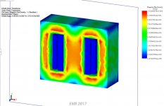
I found out that Solidworks (a very popular 3D CAD program normally used to design mechanical parts) also does magnetic flux simulations. The attached image shows a simulation of the magnetic flux inside a conventional E-I core. (Not my simulation, I found this on the 'Net here: Open & Short Circuit Transformer Simulation Tests inside SOLIDWORKS )
Long before computers and FEA (finite element analysis), scientists used a simple concept called "magnetic lines of force" to try to visualize and describe magnetic fields. It is not quantitative or exact, but the imaginary "lines of force" were found to have certain properties that always seemed to hold.
One of those properties is that the lines do not "like" to make sharp bends, and so I was almost certain, based on this old nineteenth century visualization aid, that the outside corners of a transformer core would have relatively low magnetic flux density. The lines of force would not travel right to the corners of the core.
I was right, but I did not anticipate just how dramatic the effect would be. Leaving the nineteenth century aside, let's look at the Solidworks simulation, a very 21st-century way to look at the same problem of magnetic flux density in a transformer core, but this time with considerable accuracy.
Look at the image closely. According to the scale on the right side of the image, the red areas correspond to a flux density of just over one Tesla. Meantime, the outside corners, in dark blue, correspond to a flux density of about 2.6 x 10^(-5) T.
That's 0.000026 Tesla. Which is thirty eight thousand, four hundred and sixty two times weaker than the 1 Tesla flux near the centre of the core.
Eddy currents are driven by the magnetic flux. If the flux is nearly forty thousand times weaker at the corners, so are the eddy currents there.
In other words, there is so little magnetic flux at the corners of the transformer core that you could weld them all solid, and it would make a negligible difference to the transformer.
Peavey's decision to weld their transformer corners was not stupid at all.
The microwave oven engineers who specc'd welded transformer corners are not stupid, either.
The worst we can say about these welded cores is that they make life difficult for DIY transformer rewinders. True, but hardly a unique case; manufacturing has been moving towards non-repairable products for a long time now. My entire Fender SuperChamp XD guitar amplifier was described as "not serviceable" by Fender Corp themselves - they want you to pitch it in the recycling bin if it ever stops working.
-Gnobuddy
As I said earlier, the answer is to be found in Maxwell's equations, and a suitable software program that uses them to model flux density in a transformer core.
I found out that Solidworks (a very popular 3D CAD program normally used to design mechanical parts) also does magnetic flux simulations. The attached image shows a simulation of the magnetic flux inside a conventional E-I core. (Not my simulation, I found this on the 'Net here: Open & Short Circuit Transformer Simulation Tests inside SOLIDWORKS )
Long before computers and FEA (finite element analysis), scientists used a simple concept called "magnetic lines of force" to try to visualize and describe magnetic fields. It is not quantitative or exact, but the imaginary "lines of force" were found to have certain properties that always seemed to hold.
One of those properties is that the lines do not "like" to make sharp bends, and so I was almost certain, based on this old nineteenth century visualization aid, that the outside corners of a transformer core would have relatively low magnetic flux density. The lines of force would not travel right to the corners of the core.
I was right, but I did not anticipate just how dramatic the effect would be. Leaving the nineteenth century aside, let's look at the Solidworks simulation, a very 21st-century way to look at the same problem of magnetic flux density in a transformer core, but this time with considerable accuracy.
Look at the image closely. According to the scale on the right side of the image, the red areas correspond to a flux density of just over one Tesla. Meantime, the outside corners, in dark blue, correspond to a flux density of about 2.6 x 10^(-5) T.
That's 0.000026 Tesla. Which is thirty eight thousand, four hundred and sixty two times weaker than the 1 Tesla flux near the centre of the core.
Eddy currents are driven by the magnetic flux. If the flux is nearly forty thousand times weaker at the corners, so are the eddy currents there.
In other words, there is so little magnetic flux at the corners of the transformer core that you could weld them all solid, and it would make a negligible difference to the transformer.
Peavey's decision to weld their transformer corners was not stupid at all.
The microwave oven engineers who specc'd welded transformer corners are not stupid, either.
The worst we can say about these welded cores is that they make life difficult for DIY transformer rewinders. True, but hardly a unique case; manufacturing has been moving towards non-repairable products for a long time now. My entire Fender SuperChamp XD guitar amplifier was described as "not serviceable" by Fender Corp themselves - they want you to pitch it in the recycling bin if it ever stops working.
-Gnobuddy
Attachments
When I saw the picture in post 1 my immediate thought was "why have they put the OPT right next to the input valve?". This seems to be asking for instability, which then has to be killed off with huge grid stoppers, which then provide scope for 'tube rolling' (which is actually an inconvenient form of tone control).
Magnetic hysteresis is a well know effect. Any Advanced Physics text book explains it.
Transformer Losses
Transformer Losses


I'm glad that this has actually stimulated some intelligent discussion. I've even learned more in the process.
BUT....going back to Maxwell's Equations for magnetic flux saturation, I must ask, are you taking the operating frequencies of the transformer into account?
Those equations are VERY frequency dependent. Flux will be most concentrated at the center of the core in any event but as frequency is decreased, the differential in flux density will reduce.
Now find those equations, if you care, and run the numbers in the audio frequency range as is suitable for a guitar amplifier. Let's say the range from 80 Hz to 8 KHz.
I think you will find that welding the edge of the laminations on an audio frequency transformer has much greater consequences than you might have thought, if you were basing your original estimation on doing the same thing on a microwave oven's transformer operating at 2,400,000,000 Hz.
Ultmately, I AM right, but the level to which it actually MATTERS to the performance of an audio transformer is still a matter of debate that won't be solved until someone actually takes the time to work it out mathematically using a reasonably accurate mathematical model of the transformer.
I do see this in a black and white point of view, in the sense that either (a) welding across the laminations makes NO difference, or (b) welding across the laminations makes SOME difference. Case B is the correct answer. It does make a difference. Maybe not much. But it does make a difference.
The transformer in a microwave oven operates at 50 or 60Hz, not 2.4GHz.cmjohnson said:I think you will find that welding the edge of the laminations on an audio frequency transformer has much greater consequences than you might have thought, if you were basing your original estimation on doing the same thing on a microwave oven's transformer operating at 2,400,000,000 Hz.
Ultimately, anyone who says anything affects anything/everything else is right, but only in the trivial sense of not really saying anything at all. What is more useful is to know whether something affects something else to a noticeable extent or a significant extent or an overwhelming extent.
In this particular case I would guess the effect is noticeable but not significant; the aim was probably mechanical rigidity at the expense of a minor degradation in electrical performance not important in a guitar amplifier - which would probably contain several others design 'flaws' in order to (accidentally?) get the desired sound.
Welder Transformer
New to site.
Just looking at building a hybrid or valve only guitar amp.
Possibly welded the transformer to stop it vibrating but from my earlier education electrically connecting the plates will alter the eddy currents for sure causing more heat and thus less efficiency
New to site.
Just looking at building a hybrid or valve only guitar amp.
Possibly welded the transformer to stop it vibrating but from my earlier education electrically connecting the plates will alter the eddy currents for sure causing more heat and thus less efficiency
In this particular case I would guess the effect is noticeable but not significant; the aim was probably mechanical rigidity at the expense of a minor degradation in electrical performance not important in a guitar amplifier - which would probably contain several others design 'flaws' in order to (accidentally?) get the desired sound.
That was something i was asking about before - is it possible that welding the output transformer could have enough of an effect on the transformer's distortion to change the 'sound characteristic' of the amp? A kind of by-product from mechanically stabilising the transformers.
Are we talking in the realms of minuscule distortion or measurable / audible distortion?
It's a hard road to travel to do a guitar amp comparison.
Especially if it comes as a combo with speakers and microphonics, and noting that any plausible OPT influence is related to increasing signal level where so many distortion related factors are increasing. And most listeners want to hear cranked operation with gross distortion from amp and speakers (in a hi-fi sense).
Not quite the same, and possibly reversible, one could experiment by pouring mercury in to a clamp bolt tunnel and clamp it back up without insulation
Everyone in this thread agrees with what you said so far. The question is, how much will it alter the eddy currents, and how much change in efficiency will it cause? 10%? 1%? 0.1%? 0.01%?...electrically connecting the plates will alter the eddy currents for sure causing more heat and thus less efficiency
In post #42, we found out that the magnetic flux density at the outer corners of the transformer core is four orders of magnitude weaker than it is near the coils. In fact, for the particular transformer being simulated, it was nearly forty thousand times less.
Since it is the magnetic flux that drives the eddy currents, and there is no magnetic flux to speak off at those outer corners of the core, welding them at that location will have minimal impact.
It would be a very different story if you welded the laminations solid in the regions in red in the image (in post #42). That would cause enormous eddy current losses.
-Gnobuddy
We are firmly in subjective territory now, i.e. we may not agree or learn anything.Are we talking in the realms of minuscule distortion or measurable / audible distortion?
My two cents: as an audio source, e-guitar is remarkably poor at revealing small amounts of amplifier distortion. Not only does the guitar speaker heavily roll-off treble above 5 kHz (dropping harmonic distortion products below audibility), but every note played on a guitar comes with a plethora of its own harmonics, which cover up small amounts of additional harmonic distortion from the amplifier.
To put some numbers on it, if you play a pure sine wave, or a symphony orchestra, through an amp with 10% mostly second-harmonic distortion, connected to a decent pair of monitor speakers, all but the truly cloth-eared will hear audible distortion.
By contrast, if you play an electric guitar through a valve guitar amp with 10% mostly second harmonic distortion, my experience is that very few will notice anything. It still sounds like a "clean" guitar tone, not a distorted one.
This is about the amount of distortion you get from a single half-12AX7 pushed to nearly full output (but not clipped). Even a "clean" guitar amp adds considerably more distortion than this, as the signal goes through several triodes and a pentode.
So my vote regarding the audibility of the OT corner welds is firmly in the "There will be no audible difference" camp.
Even if it turns out there is a barely detectable change in sound, I'll bet it'll be far less significant than the sound (THD) increase from turning up the amp's gain a smidge, and therefore, entirely irrelevant.
However, if you ask the marketing department at Mercury Magnetics, I'm sure they will gladly explain to you how welded transformer corners will make baby Jesus cry and destroy your guitar tone, a tragedy you can avoid by spending a month's salary on a pair of their own Mercury Magnetics transformers which have been blessed by a magic unicorn before being packed in boxes lined with mermaid-hair.
-Gnobuddy
Haha, When I looked at the first picture I thought the dumb thing was how close the two power tubes are to each other..... Look how big the chassis is.
Waaaaay to close....
I was looking at the case and placements of everything, seems like a horrible layout, even for my t00bn00b eyes.
But then I saw the 60w speaker out and the signal in/out sockets seem to be 100% identical. I would say that is the biggest no-go here.
Edit:
No wonder there's hum in those things...
Last edited:
I saw the 60w speaker out and the signal in/out sockets seem to be 100% identical.
The early guitar amp builders saw fit to use a 1/4 inch phone jack for both the guitar cable and the speaker cable. Unfortunately, in the interest of compatibility, that's still the common standard today.
Marshall and others adopted an isolated plastic jack for the guitar input breaking that ground loop path, but a pair of cheap metal jacks is still seen on some new stuff.
The real fun happens when Mr. Mega Bass Player uses a common guitar cord to connect his 300 Watt vacuum tube Ampeg SVT up to the speaker cabinet and the cable goes open during some cranked bass solo leaving the amp without a load. SVT's have been known to spontaneously combust under these conditions.
I agree, what a horrible choice. But a very common one, not only in valve guitar amps, but even in vintage solid-state P.A. amps and powered mixers and loudspeakers....the 60w speaker out and the signal in/out sockets seem to be 100% identical. I would say that is the biggest no-go here.
One of my jam buddies has an old Yamaha powered mixer. Like most mixers, the top face and rear panel are both littered with 1/4" jacks - line inputs, effects sends, headphone outs, control room submixes, you name it. And in the middle of all those, there are two 1/4" jacks - identical in appearance to all the rest - which are the speaker outputs for the 250+250W stereo power amp built into the mixer.
-Gnobuddy
Actually, one weld bead will not be a problem, even if it's in the red area. The problem arises when there is more than one weld bead, and the flux goes between the beads.Everyone in this thread agrees with what you said so far. The question is, how much will it alter the eddy currents, and how much change in efficiency will it cause? 10%? 1%? 0.1%? 0.01%?
In post #42, we found out that the magnetic flux density at the outer corners of the transformer core is four orders of magnitude weaker than it is near the coils. In fact, for the particular transformer being simulated, it was nearly forty thousand times less.
Since it is the magnetic flux that drives the eddy currents, and there is no magnetic flux to speak off at those outer corners of the core, welding them at that location will have minimal impact.
It would be a very different story if you welded the laminations solid in the regions in red in the image (in post #42). That would cause enormous eddy current losses.
-Gnobuddy
Two beads on the outer edges should not be much of an issue.
What I have not seen mentioned yet, is that a weld bead will bond all the laminations electrically together. That means that all you have to do is bond one lamination or the bead to the chassis in order to prevent any of the laminations from becoming electrically hot to ground in the event of a mishap with the windings.
btw, nobody noticed the real flaw in the picture...
All the labels are upside down....
jn
I agree, what a horrible choice. But a very common one, not only in valve guitar amps, but even in vintage solid-state P.A. amps and powered mixers and loudspeakers.
Thank *insert random deity* that we now have speakon, hopefully someone will wake up and come to their senses.
And for a good reason......
All the labels are upside down....
...but you already know that.
btw, nobody noticed the real flaw in the picture...
All the labels are upside down....
jn
That phrase has forced me to go to the first post and look at the picture and wow! There is a point that nobody mentioned either, someone mentioned this:
" Due to cost cutting, welding transformers instead of screwing have become very common over the past decades. "
But the transformer is not welded to the chassis, the weld is on an intermediate metal plate, (of considerable thickness) which in turn is screwed to the chassis. I suppose that is because the thin material of the chassis would not support direct welding, also it has a galvanic anticorrosion process that would probably make it difficult for a correct transfer of the electrode material from one surface to the other. But then why did they solder it? Perhaps, and giving as ground the argument of the OP and enough of what is said here, is a benefit sought ex-professed by the people of Peavey ....
I think this phrase was mentioned by the OP, does it make sense, or not?
Transformer - Wikipedia
" Stray losses Leakage inductance is by itself largely lossless, since energy supplied to its magnetic fields is returned to the supply with the next half-cycle. However, any leakage flux that intercepts nearby conductive materials such as the transformer's support structure will give rise to eddy currents and be converted to heat. "
- Status
- This old topic is closed. If you want to reopen this topic, contact a moderator using the "Report Post" button.
- Home
- Live Sound
- Instruments and Amps
- The dumbest thing I've ever seen in amp construction....