The cap I’m using is actually smaller than the footprint as well, but moving
it down a bit could make space for some more capacitor options...
OK, good luck.
I realize this wing of the forum is not the most active, and people generally don't post many build logs for the instrument amps and gadgets, but i figured i'd keep this updated for information in case anyone might be interested in building their own Ruby in the future. I can recommend it, it is a nice sounding low-power amp and will get pretty loud with efficient guitar speakers (which seems more the rule than the exception).
Now, the project actually started out as an idea to build a 5F2 style amp, but i've been a little strapped for DIY cash recently, so I've putting off buying lots of iron. But I had a lot of wood lying around so i wen't hunting for something a bit cheaper, which led me to the Ruby.
So while waiting for the final PCB and parts to arrive, here is a few pictures from the cabinet building process. I actually built this during easter, so im cheating with the chronology... In any case, this was a fun and educational experience and i will happily recommend anyone on the fence about building their own guitar amp to just go for it.
Wood was some fairly cheap pine plywood (7 ply) that i had bought a sheet off for a portable outdoor work bench. I had initially wanted to do a nice box jointed box but the jig i'd bought (cheaply) off fleabay went and broke on me so that plan was scrapped in favor of rabbets (rebates?). I recently invested in a new festool circular saw and their relatively new track system that allows precise settings of angles etc for miter cuts. We live in a small city apartment with only a little yard, so nothing like space for a table saw or real miter saw, so this is my portable solution that i can stow away when not in use.

 I took the straightest piece of wood i could find at the hardware store, but it did have a little warp and the box ended up not perfectly square, but good enough for guitar.
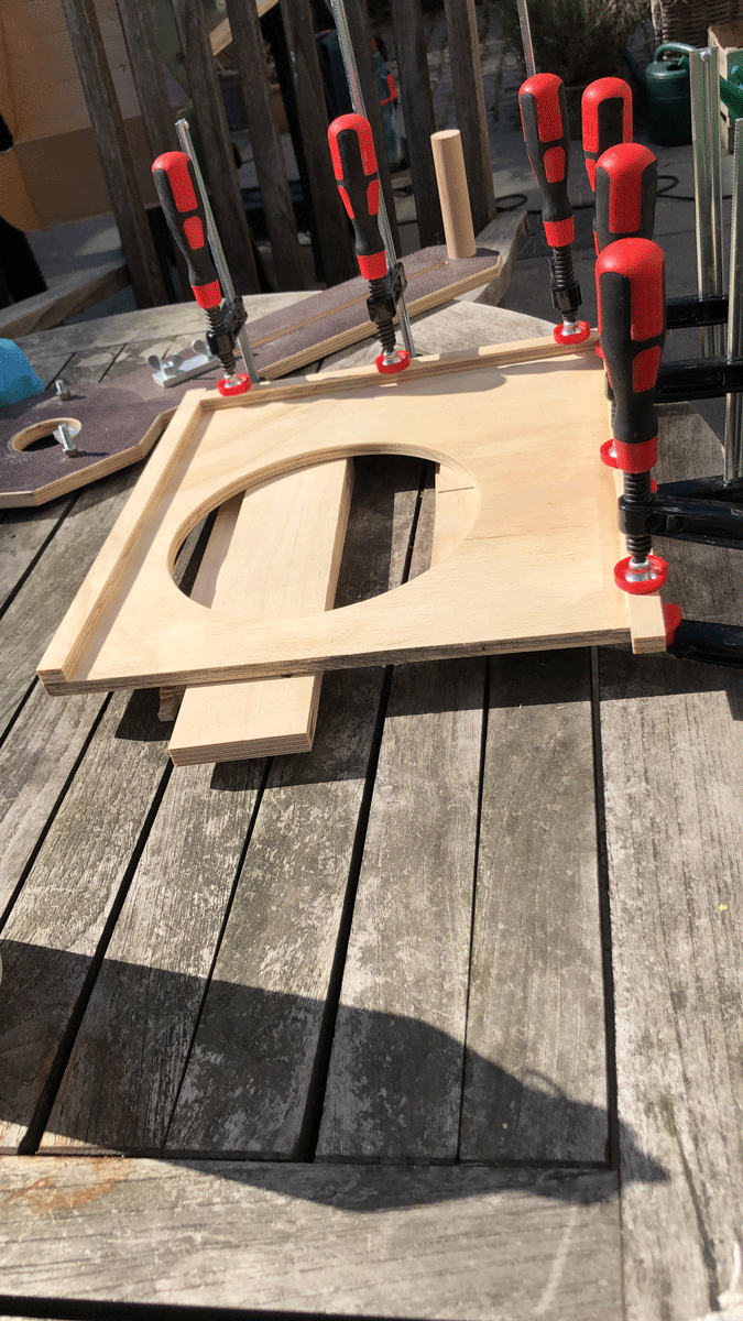
Next up my new saw made it very easy to do the cutouts for the front panel, fender tweed style. Again i used left over 12mm plywood for the panels. This was a nicer ply with more layers than what i'd used for the box but the difference is not too noticeable.
 While those were gluing i got started on the baffle. The idea was to keep it pretty close to classic fender tweed as mentioned, including a floating baffle from some scrap 8mm ply i picked up in a local shop. The one little scrap piece was enough for the baffle and panels. I made the cutout for a Jensen C8R i'd gotten cheap off local classified ads.
So up next, trim the excess off the front panels with the flush trim bit on my router and test fit the baffle.
 So far so good. Then round the corners with a roundover bit on the router, test fit speaker and drill holes for baffle mounting screws. Now for the finish. I got some tweed imitation grill cloth from music store and had my fun trying to get that tight on the box. Note: don't try to staple this stuff on with a cheap hardware store stapler. It wont work...
 For the cabinet i'd decided against cloth covering. I know my own temperament well enough to know that would probably put me in a bad mood for weeks if i attempted this, so that is for a future amp. Instead a couple of coats of tinted water-based floor varnish followed by three coats of very tough clear matte varnish on top. This is the first layer. I did an oops on the back panel, but hey...

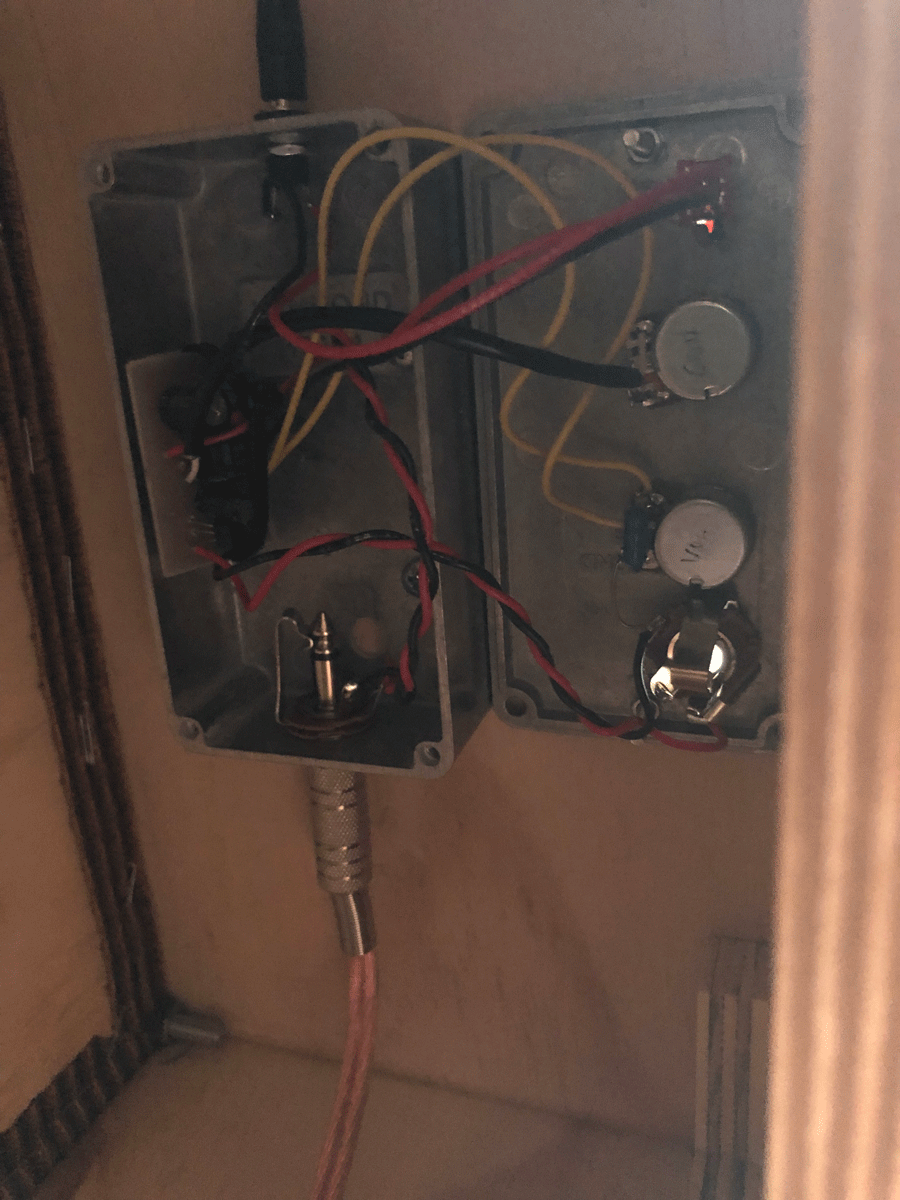
The actual Ruby amp i used was handmade by etching and thrown together in a very slapdash manner. I made a design to fit the knobs for the cabinet cutout though so it would at least have some semblance of a proper amp...

I was pretty optimistic in my choice of cabinet, and the whole thing didnt fit the Hammond 1590B i'd bought, so i ended up with an improvised mounting solution... But hey again, it's out of the way hidden behind a panel on the back so noone will ever be the wiser... Once i've got all the parts together for the new PCB i will fit it in a proper chassis and do something a bit more solid and tidy.
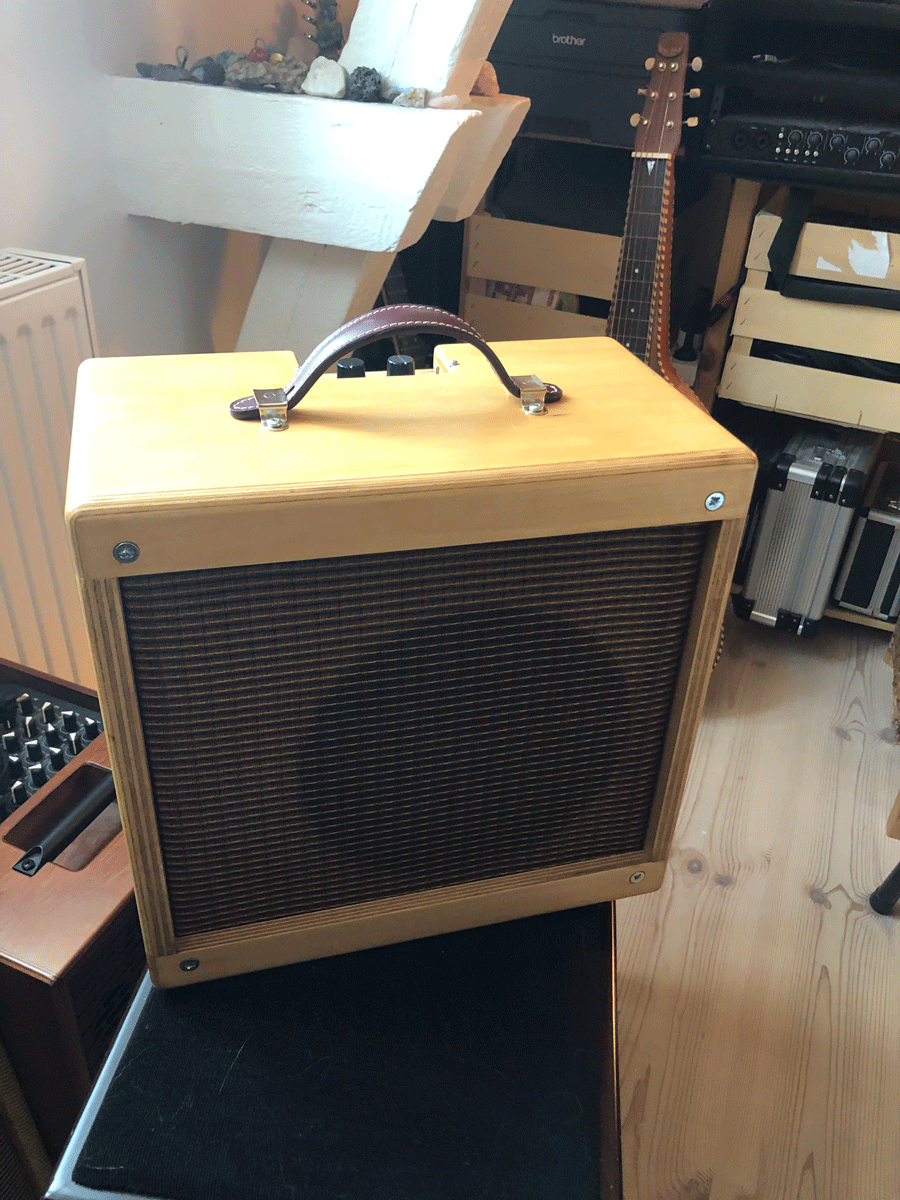
So finally, with all the bits in place, here is the finished amp. It sounds nice to my ears, and having relied on a DIY bassman for a while until now, it is really nice to be able to dial in some crunchy overdrive on the amp without sacrificing my hearing too much. I am actually surprised by how nicely this amp distorts, it is not as organic as the bassman but its close and it doesn't cause the windows to rattle and nails to loosen from the walls so i'll take it.
More to come once the parts for the properly assembled amp arrive...
Now, the project actually started out as an idea to build a 5F2 style amp, but i've been a little strapped for DIY cash recently, so I've putting off buying lots of iron. But I had a lot of wood lying around so i wen't hunting for something a bit cheaper, which led me to the Ruby.
So while waiting for the final PCB and parts to arrive, here is a few pictures from the cabinet building process. I actually built this during easter, so im cheating with the chronology... In any case, this was a fun and educational experience and i will happily recommend anyone on the fence about building their own guitar amp to just go for it.
Wood was some fairly cheap pine plywood (7 ply) that i had bought a sheet off for a portable outdoor work bench. I had initially wanted to do a nice box jointed box but the jig i'd bought (cheaply) off fleabay went and broke on me so that plan was scrapped in favor of rabbets (rebates?). I recently invested in a new festool circular saw and their relatively new track system that allows precise settings of angles etc for miter cuts. We live in a small city apartment with only a little yard, so nothing like space for a table saw or real miter saw, so this is my portable solution that i can stow away when not in use.
Next up my new saw made it very easy to do the cutouts for the front panel, fender tweed style. Again i used left over 12mm plywood for the panels. This was a nicer ply with more layers than what i'd used for the box but the difference is not too noticeable.
So up next, trim the excess off the front panels with the flush trim bit on my router and test fit the baffle.
The actual Ruby amp i used was handmade by etching and thrown together in a very slapdash manner. I made a design to fit the knobs for the cabinet cutout though so it would at least have some semblance of a proper amp...
I was pretty optimistic in my choice of cabinet, and the whole thing didnt fit the Hammond 1590B i'd bought, so i ended up with an improvised mounting solution... But hey again, it's out of the way hidden behind a panel on the back so noone will ever be the wiser... Once i've got all the parts together for the new PCB i will fit it in a proper chassis and do something a bit more solid and tidy.
So finally, with all the bits in place, here is the finished amp. It sounds nice to my ears, and having relied on a DIY bassman for a while until now, it is really nice to be able to dial in some crunchy overdrive on the amp without sacrificing my hearing too much. I am actually surprised by how nicely this amp distorts, it is not as organic as the bassman but its close and it doesn't cause the windows to rattle and nails to loosen from the walls so i'll take it.
More to come once the parts for the properly assembled amp arrive...
Attachments
-
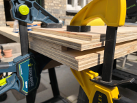 Photo-17-04-2019,-14.05.png470.7 KB · Views: 282
 -
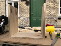 Photo-17-04-2019,-14.24.png581.4 KB · Views: 286
 -
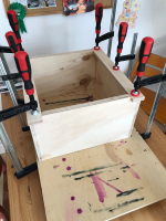 Photo-18-04-2019,-13.25.png469.9 KB · Views: 300
 -
 Photo-18-04-2019,-14.59.png468.9 KB · Views: 337
 -
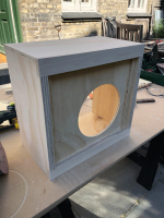 Photo-18-04-2019,-15.54.png494.4 KB · Views: 294
 -
 Photo-14-05-2019,-20.12-.png468.4 KB · Views: 285
 -
 Photo-14-05-2019,-20.12--.png536 KB · Views: 255
 -
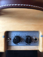 Photo-14-05-2019,-20.12.png427.1 KB · Views: 273
 -
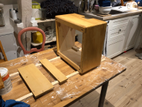 Photo-28-04-2019,-21.50.png513.9 KB · Views: 269
 -
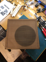 Photo-25-04-2019,-22.23.png568.9 KB · Views: 275
It's been truly moribund in recent months.I realize this wing of the forum is not the most active

I'm hoping things will pick up when winter arrives in the Northern hemisphere, and people are forced to spend more time indoors, but we shall see.
Have you considered the trick of using 70-volt audio line transformers as valve amp output transformers? These types of transformers can be ridiculously inexpensive (like $5 - $10 USD), and there seem to have been quite a few successful DIY guitar amp builds using them.I've putting off buying lots of iron.
On the power transformer side of things, there are intriguing possibilities there as well. Like using a 12V wall-wart (switching power supply) to power 12V heaters, and also to power a boost converter for the HT ( Amazon.com: 8-32V to 45-390V DC-DC Boost Converter Step Up Power Supply Module High Voltage ZVS Capacitor Charging Board: Gateway ).
Someone posted on diyAudio that he'd built a single-ended 6V6 guitar amp with that boost module providing the HT, so apparently it can cope with the amount of power needed for something like a Champ (and possibly more.)
Very nice!here is the finished amp.
-Gnobuddy
Very nice build.
In much of the world these transformers are being replaced by electronic equivalents, so they are dirt cheap second hand.
Have a look at the various builds by GCWills over on AGGH
+1 and, given your wall voltage is 220V, have a look for halogen lighting transformers, which work nicely as a single ended EL34 or 6L6 amp.Have you considered the trick of using 70-volt audio line transformers as valve amp output transformers? These types of transformers can be ridiculously inexpensive (like $5 - $10 USD), and there seem to have been quite a few successful DIY guitar amp builds using them.
In much of the world these transformers are being replaced by electronic equivalents, so they are dirt cheap second hand.
Have a look at the various builds by GCWills over on AGGH
Thank you Gnobuddy and theoglette. Sounds like some interesting alternatives, though I am not sure where to get hold of either type of transformer in my neck of the woods. I guess I should look around some surplus stores for old halogen lamp warts. Whereabouts does one find 70V line transformers? Surplus or new?
I can see that I have some reading to do here, since im not trained in EE things and so still learning as I’m going along, but the ideas are very welcome
In the meantime I can report that I received the boards and they work nicely I’ll post a couple more photos when I’m at my pc again.
I can see that I have some reading to do here, since im not trained in EE things and so still learning as I’m going along, but the ideas are very welcome
In the meantime I can report that I received the boards and they work nicely
I’ll post a couple more photos when I’m at my pc again.Here in British Columbia, there seem to be no halogen transformers to be found in 2019. At least, I haven't been able to find a single one....I am not sure where to get hold of either type of transformer in my neck of the woods.
According to an electrician I spoke with, they were ripped out of all government-owned buildings and scrapped more than a decade ago. They were replaced with high-efficiency compact fluorescent lights. The electrician in question was one of many hired to do this job, so he remembered it well.
(I've seen solid-state substitutes on Amazon and Ebay, but those are useless for our purposes. They are not transformers, but electronic switching devices that lower the AC mains voltage to the 12V that halogen bulbs want.)
Audio line transformers are still very much around, though. These are designed for use in buildings where sound (music and/or voice announcements) has to be distributed over a wide area, such as warehouses, large stores, businesses, railway stations, major bus depots, et cetera.
The trouble is that long wires running to 8 ohm or 4 ohm speakers cause huge electrical losses, and also, the various loudspeakers need to be set up for different loudnesses; you probably want much quieter background music in the bathrooms compared to the machine-shop or loading dock.
So the clever solution was to design the audio power amplifier to spit out a relatively high voltage (nominally 70.71 volt) audio signal, which is run via long wires to all the speakers. But at each speaker, there is a little step-down transformer. The transformer primary is driven by the "70V" audio, while it's secondary spits out reduced voltage (and increased current) to drive the loudspeaker. To allow loudness adjustment, the transformer usually has multiple taps on the primary (the 70V side.)
I should mention that some countries used 100V lines (rather than 70.71V). I have also seen transformers designed for 25V. If you have a choice, 100V or 70.71V transformers are more likely to work for our purposes as valve guitar amp OTs.
The various taps on the transformer primary are labelled with the corresponding nominal power delivered to the speaker. For example, if there is a tap marked "0.625W", the step-down ratio is such that if you apply 70.71 volts AC to the primary, 0.625 watts will be delivered to the 8 ohm speaker.
We can use this to back-calculate the primary impedance, which is what we need to investigate suitability for use as a valve amp OT. More on that in a minute.
As you have probably guessed by now, these little transformers are known as audio line transformers. Because they are manufactured by the tens of thousands, and serve an unglamourous behind-the-scenes role, they are inexpensive. (Well, they were inexpensive. Prices at Parts Express (USA) seem to have tripled since I last looked, presumably as a result of Trump's idiotic tariff wars with China.)
You will usually find them at businesses that supply ceiling-mount paging speakers to contractors. Here in Canada, for example, I found a company called Qcomponents that sells several (e.g. Quam TCH70 ).
In the USA, Parts Express carries several: Quam TCH70 10W-70V Low-Loss Extended LF Speaker Line Matching Transformer
While these transformers were never intended for valve guitar amp output transformer use (and most guitar amp builders had never heard of them), a very clever Australian named Paul Cambie figured out that they had all the right electrical properties for this usage: http://home.alphalink.com.au/~cambie/6AN8amp/M1115.htm
An enthusiastic valve guitar amp builder by the name of Grant Wills read Cambie's page, and built an early valve amp using Cambie's idea: Grant Wills
Another extremely smart Aussie, Roly Roeper, leapt on the idea as part of his plan to design an affordable, easy-to-build valve guitar amp for beginners: Cheap Output Transformers
Since that time, I've found threads on DIY guitar amps using audio line transformers all over the 'Net. Many are from Australia, where the idea originated, and was first explored. But I've also seen similar threads from the USA, Canada, and several other countries.
This post is already too long, so I'll post details separately on the mathematics you use to calculate what we want to know, i.e., the primary impedance in ohms at each transformer tap.
-Gnobuddy
Last edited:
Okay, let's take a look at how to figure out the primary impedance of one of these inexpensive audio line transformers.
From the Quam TCH70 page on the Parts Express website, we have this:
Okay, let's take a closer look at, say, the 0.625W tap (each tap is half the power of the next, so Quam's "0.63W" is a sensibly rounded-up 0.625W; I'll use the more accurate number for calculations, with the understanding that a real-world transformer most certainly does not have three-digit precision in its turns ratio!)
When a voltage V is applied to a resistor R, the power delivered is V*V/R. A little algebra lets us rewrite this as V = square root(P*R).
So if 0.625W is being delivered to 8 ohms, the voltage across the speaker must be square root(0.625*8), which works out to 2.236 volts. This is the voltage across the transformer secondary.
We know the transformer is designed to deliver this power of 0.625W to the speaker when there is 70.71 volts AC across the primary winding.
Since we know both primary and secondary voltages, we can now calculate the step-up ratio (same as turns ratio) from secondary to primary. It's just the ratio of voltages, i.e. (70.71/2.236), which works out to 31.622.
From transformer theory, the impedance ratio is the square of the turns ratio. Squaring 31.622 gives us 999.98; clearly the transformer designers intended this ratio to be 1000.
Now multiply this impedance ratio by the speaker resistance, which gives us the impedance seen on the primary side of the transformer. With an 8 ohm speaker and an impedance ratio of 1000, that means the transformer's primary impedance is 8000 ohms, or 8 kilo ohms.
As it happens, this is a value that's been used in a number of small valve guitar amp designs over the years, so at this point, this particular transformer is beginning to look usable, though we must keep in mind the transformer is only rated for a maximum of 10 watts of power handling. (This rating is down to 50 Hz though, while a guitar doesn't go below 82 Hz, which means this transformer will handle considerably more power for use with guitar.)
There is one last thing left to do. We need to find the centre-tap of the primary winding, so we can use it with a push-pull output stage.
The easy way is to consider that we want a tap that delivers twice as much voltage to the speaker (i.e., there are half as many turns on the primary side, so this is the centre tap.) Twice the speaker voltage translates to four times the power delivered to the speaker; so we want the tap that's rated for four times 0.625 watts. This, of course, means we want the 2.5 watt tap - this will be the centre-tap of our primary.
To sum up, we can now use this particular transformer as an 8k OT in a push-pull valve guitar amp of maybe 10 to 15 watts rated output; we will connect one output valve anode to the "common" primary tap, the other output valve anode to the "0.625W" tap, and B+ to the "2.5W" tap, which we now know is the primary centre-tap.
Make sense?
-Gnobuddy
From the Quam TCH70 page on the Parts Express website, we have this:
Note that the primary will have a wire marked "common" as well as the various other taps mentioned above. The "common" wire will be one end of the primary winding, and the incoming audio signal will be applied between "common" and one of the various taps.Parts Express said:The Quam TCH70 is a constant voltage line transformer with multi-tap outputs, designed for use in 70V distributed audio systems. Primary taps are 10, 5, 2.5, 1.25 and 0.63 watts. Primary leads are 12" pre-cut, color coded; secondary leads are 6" pre-cut and color coded. Extended frequency response of 50 - 20,000 Hz.
Okay, let's take a closer look at, say, the 0.625W tap (each tap is half the power of the next, so Quam's "0.63W" is a sensibly rounded-up 0.625W; I'll use the more accurate number for calculations, with the understanding that a real-world transformer most certainly does not have three-digit precision in its turns ratio!)
When a voltage V is applied to a resistor R, the power delivered is V*V/R. A little algebra lets us rewrite this as V = square root(P*R).
So if 0.625W is being delivered to 8 ohms, the voltage across the speaker must be square root(0.625*8), which works out to 2.236 volts. This is the voltage across the transformer secondary.
We know the transformer is designed to deliver this power of 0.625W to the speaker when there is 70.71 volts AC across the primary winding.
Since we know both primary and secondary voltages, we can now calculate the step-up ratio (same as turns ratio) from secondary to primary. It's just the ratio of voltages, i.e. (70.71/2.236), which works out to 31.622.
From transformer theory, the impedance ratio is the square of the turns ratio. Squaring 31.622 gives us 999.98; clearly the transformer designers intended this ratio to be 1000.
Now multiply this impedance ratio by the speaker resistance, which gives us the impedance seen on the primary side of the transformer. With an 8 ohm speaker and an impedance ratio of 1000, that means the transformer's primary impedance is 8000 ohms, or 8 kilo ohms.
As it happens, this is a value that's been used in a number of small valve guitar amp designs over the years, so at this point, this particular transformer is beginning to look usable, though we must keep in mind the transformer is only rated for a maximum of 10 watts of power handling. (This rating is down to 50 Hz though, while a guitar doesn't go below 82 Hz, which means this transformer will handle considerably more power for use with guitar.)
There is one last thing left to do. We need to find the centre-tap of the primary winding, so we can use it with a push-pull output stage.
The easy way is to consider that we want a tap that delivers twice as much voltage to the speaker (i.e., there are half as many turns on the primary side, so this is the centre tap.) Twice the speaker voltage translates to four times the power delivered to the speaker; so we want the tap that's rated for four times 0.625 watts. This, of course, means we want the 2.5 watt tap - this will be the centre-tap of our primary.
To sum up, we can now use this particular transformer as an 8k OT in a push-pull valve guitar amp of maybe 10 to 15 watts rated output; we will connect one output valve anode to the "common" primary tap, the other output valve anode to the "0.625W" tap, and B+ to the "2.5W" tap, which we now know is the primary centre-tap.
Make sense?
-Gnobuddy
Gnobuddy,
Thank you for your explanations, perfect for a nonEE dummy like myself. Luckily I do work as a scientist, though in biochemistry, so I even managed to keep up with the algebra I still need to look into where I can my hands on these things in my neck of the woods, but knowing what I’m looking for makes that part a lot easier!
I’ve got a shop here that sells them, but they are 100v transformers. But I guess a 100V transformer with a 1,5w tap should work? That comes to a turns ratio of 28.7, or a primary impedance of 6,6kohm approx. am I right to think that could work with something like a 6L6 or EL34? The center tap is then the 6w line if I follow your logic. Will these also work for SE amps? I am not sharp enough on the theory here to determine if not and why...
And adding to this: given such a small OPT, what are the options for PP designs that fit a 6.6k load and run to only a few watts? Let’s throw “and sound good” into the mix, although I know it gets subjective here...
Finally, how do they sound??
Thank you for your explanations, perfect for a nonEE dummy like myself. Luckily I do work as a scientist, though in biochemistry, so I even managed to keep up with the algebra
I still need to look into where I can my hands on these things in my neck of the woods, but knowing what I’m looking for makes that part a lot easier!I’ve got a shop here that sells them, but they are 100v transformers. But I guess a 100V transformer with a 1,5w tap should work? That comes to a turns ratio of 28.7, or a primary impedance of 6,6kohm approx. am I right to think that could work with something like a 6L6 or EL34? The center tap is then the 6w line if I follow your logic. Will these also work for SE amps? I am not sharp enough on the theory here to determine if not and why...
And adding to this: given such a small OPT, what are the options for PP designs that fit a 6.6k load and run to only a few watts? Let’s throw “and sound good” into the mix, although I know it gets subjective here...
Finally, how do they sound??
Last edited:
Come on, now, I've never met a scientist who was a dummy!...dummy...scientist
I didn't double-check your math, but assuming the numbers are correct, I have certainly heard of 6.6k primary OTs, even in some Fender amps.I guess a 100V transformer with a 1,5w tap should work? That comes to a turns ratio of 28.7, or a primary impedance of 6,6kohm approx. am I right to think that could work with something like a 6L6 or EL34?
I don't have much exposure to big, loud guitar amps, and have literally never seen a 6L6 in the flesh. So I honestly don't know what load impedance was usually used with them. But when in doubt, I draw the load-line on the valve characteristic curves, and that lets me know if a given primary impedance will work or not.
(You can also change B+ voltage to move the load-line around, so a transformer that's not well suited for one B+ voltage might work fine with another.)
Yes, it's always the tap rated for four times the power (of the other tap you plan to use.)The center tap is then the 6w line if I follow your logic.
The textbook-standard answer is "No!", because for SE use, transformers have to tolerate a large DC current through the primary, which would normally produce a large DC magnetization in the core, which in turn means the transformer is likely to saturate prematurely when AC is added.Will these also work for SE amps?
So SE transformers have a deliberate "air gap" in the core, which lowers the amount of magnetic flux; to compensate, the transformer itself has to be bigger and heavier than the push-pull equivalent.
That said, I have actually read more than one thread in which someone who is not an EE, rushing in where angels fear to tread, simply hooked up one of these cheap audio line transformers to an SE valve amp, and found that it worked just fine for him.
I think the key to making this work is to over-rate the transformer. If you use a cheap 10 W audio line transformer in a tiddly SE amp that puts out, say, 2 watts, there's a good chance the transformer will cope with the small amount of DC current and AC power.
Firstly, is 1.5W really the lowest-power tap you can find on an audio line transformer? A lower-wattage tap will yield a higher primary impedance, and it may be easier to find valves to work with that.what are the options for PP designs that fit a 6.6k load and run to only a few watts?
(I made up a spreadsheet some years ago with data for various audio line transformers, and I'm pretty sure I have primary impedances up to about 20k there. I forget how many watts that corresponds to.)
That said, if you must use 6.6k, each valve sees only 3.3k in class A operation and only 1.65k during the class B part of its cycle. So we're looking for a low-power valve that can supply (relatively speaking) a lot of current, and run from a low B+ voltage.
I'm not sure what's suitable in Europe, but here in North America, I would immediately head for the 50C5 and family: small output pentodes from the era of the "All American Five" valve radios. They were designed to run on rectified 120V AC without a transformer (deadly dangerous
), and to drive something like a 2k OT primary. I won't be sure until I draw a load-line, but I suspect a pair of these valves would work with a 6.6k OT in push-pull. As a bonus, they can be found very cheaply, because Leo Fender never used them, and the audiophiles would never stoop to using a valve designed for use in cheap radios.The 50C5 itself has an awkward 50-volt heater. Luckily, it came in other flavours too, identical except for heater voltage. One of these is the 12C5 or 12CU5, which has a 12-volt heater. Perfect. (There is also a 17C5 and a 25C5, with corresponding heater voltages. Be aware that there is a North American valve named 35C5, but it is NOT a 35-volt version of the 50C5. It's similar, but smaller and lower-rated.)
Indeed it does!Let’s throw “and sound good” into the mix, although I know it gets subjective here...
Guitar sounds now span such a wide range that it's really difficult to define "good". Many metalheads love guitar sounds which sound utterly horrible to me, like power tools grinding on a tin roof...and they'd probably be totally bored by the relatively tiny amounts of bluesy distortion I prefer.I've never built a pp 12C5 amp, though it is actually on my mental list of projects. But a diyAudio user named, I think, Lingwedl, posted about a PP 50C5 amp he'd built for someone else, which he liked a lot.
I did build a roughly 2-watt PP amp using a pair of 6AK6 pentodes, but those required an OT with a primary impedance around 20 - 25 kilo ohms. I think it sounds good, and it's too loud to use at home!
-Gnobuddy
Well, with electronics i am still a dummy, with my actual work i prefer to think i'm not
Thank you for your detailed response to my questions! I am sorry i cannot reply in more detail, but you've given me lots of food for thought, and i will look into some of the examples you mention for inspiration. My example was just rough and ready looking through the catalogue of a local shop, so i'm sure you're right that it should be possible to get something with a higher impedance to make life easier. This goes on my to do list for future projects
Thank you for your detailed response to my questions! I am sorry i cannot reply in more detail, but you've given me lots of food for thought, and i will look into some of the examples you mention for inspiration. My example was just rough and ready looking through the catalogue of a local shop, so i'm sure you're right that it should be possible to get something with a higher impedance to make life easier. This goes on my to do list for future projects
Call me the broken record.: I seem to be spending May re-posting old posts.
Or maybe I'm just having an in-forum sabbatical (apologies to Scott Adams)
Anyway, look here for some info on how to use PA iron as PP OPTs Cheap Output Transformers
Or maybe I'm just having an in-forum sabbatical (apologies to Scott Adams)
Anyway, look here for some info on how to use PA iron as PP OPTs Cheap Output Transformers
...that link was already posted in my post #29....look here for some info on how to use PA iron as PP OPTs Cheap Output Transformers
-Gnobuddy
I thought it was somewhere in here...that link was already posted in my post #29.
Ah. Clearly today is "deja vu all over again"
One of my favourite films is "Groundhog Day".Clearly today is "deja vu all over again"
In case you've never heard of it: Groundhog Day (1993) - IMDb
-Gnobuddy
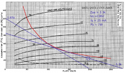
Something to ponder: a load-line for a pair of 12C5 (or 17C5, 25C5, 50C5) in push-pull.
The essentials are a 3.3k Zaa OT, 200V B+, each 12C5 biased to 25mA, resulting in estimated output power just under 7 watts RMS.
The 200-volt B+ is a bit of an awkward value. For a cheap-n-cheerful amp, I would drop that to 170 volts (diode-rectified 120V AC), which would allow the use of a cheap 120V:120V mains isolation transformer as the power transformer. Output power will drop, but for home use, it'll probably be too loud either way.
For heater power I would use a 12V DC wall-wart or switching power supply module, which can power both the 12C5s and any of the various 12-volt preamp triodes and small-signal pentodes for the preamp.
-Gnobuddy
Attachments
- Status
- This old topic is closed. If you want to reopen this topic, contact a moderator using the "Report Post" button.
- Home
- Live Sound
- Instruments and Amps
- 2-sided board for Ruby Amp