Okay, the last conversion to guitar amp project was a success so it's time for another one!  I have on the way to me 1 Akai M8 Reel to Reel Amplifier, right side only (originally designed as mono with right only engaged or stereo when selected engaging a left side amp). I'm told it's working condition but we shall see how its doing once it arrives. In the mean time lets get planning for what needs to be done.
What we have for tubes:
1 x EF86 & 1 x 12AX7 in preamp,
1 x 6X4 rectifier,
1 x EL84 output
Transformer is putting out 250V
Speaker Out is 8 Ohms
Max output to speakers is 6 watts (probably less)
Schematic is attached with signal path traced out as best I can figure. There is a bit of a convoluted thing where the EF86 is driving the Volume pot and the 12AX7 drives the Tone pot/Speed selector knob. Or at least that's what I think is going on. I'll know for sure when the model arrives.
I'm thinking of gutting this one much further than the last amp and doing something like the 60's Vox AC4 design. Looks to me like we've got more than sufficient iron for it and the tube compliment is a 90% match already. I've seen other people do conversions differently on these, keeping the circuit more intact as it was originally designed, but I'm pretty sure a Vox AC-4 mod is the way I'd like to go. Anyone see anything different or have any tips/twists on the AC4 circuit that I should be looking at?
Before anyone says it, yes I'm aware that EF-86 tubes have issues going microphonic in guitar amps. I will be using the same adapter that I used on my last conversion allowing the tube socket to accept a 6AU6 pentode. It works great and is close enough to an EF-86 that the amp functions the same.
As always any input is welcome and appreciated! I may not get to answering any questions or comments for a few days until I have the unit in hand, but rest assured I will respond soon as I'm able.
I have on the way to me 1 Akai M8 Reel to Reel Amplifier, right side only (originally designed as mono with right only engaged or stereo when selected engaging a left side amp). I'm told it's working condition but we shall see how its doing once it arrives. In the mean time lets get planning for what needs to be done.What we have for tubes:
1 x EF86 & 1 x 12AX7 in preamp,
1 x 6X4 rectifier,
1 x EL84 output
Transformer is putting out 250V
Speaker Out is 8 Ohms
Max output to speakers is 6 watts (probably less)
Schematic is attached with signal path traced out as best I can figure. There is a bit of a convoluted thing where the EF86 is driving the Volume pot and the 12AX7 drives the Tone pot/Speed selector knob. Or at least that's what I think is going on. I'll know for sure when the model arrives.
I'm thinking of gutting this one much further than the last amp and doing something like the 60's Vox AC4 design. Looks to me like we've got more than sufficient iron for it and the tube compliment is a 90% match already. I've seen other people do conversions differently on these, keeping the circuit more intact as it was originally designed, but I'm pretty sure a Vox AC-4 mod is the way I'd like to go. Anyone see anything different or have any tips/twists on the AC4 circuit that I should be looking at?
Before anyone says it, yes I'm aware that EF-86 tubes have issues going microphonic in guitar amps. I will be using the same adapter that I used on my last conversion allowing the tube socket to accept a 6AU6 pentode. It works great and is close enough to an EF-86 that the amp functions the same.
As always any input is welcome and appreciated
! I may not get to answering any questions or comments for a few days until I have the unit in hand, but rest assured I will respond soon as I'm able.Attachments
There are some interesting ideas in this AC4-inspired DIY amp on EL34 World: "Doug Circuits" VOX AC4 Ver.3...any tips/twists on the AC4 circuit that I should be looking at?
-Gnobuddy
RECTIFIER TUBE QUESTION:
I'm still working out a schematic for my take on the Vox AC4 circuit for this build. I'm getting a little hung up on a rectifier tube question. Can someone out there with a better understanding of reading these old tube charts double check my conclusions below please? Tube data charts attached.
The 60's Vox AC4 schematic shows a 6V4 rectifier tube, according to the data sheet when supplied with 250V that should yield a max DC output of 90 mA & a little over 260V.
The data sheet for the 6X4 tube in my Akai unit shows a max DC output of 70mA & also a little over 260V when supplied with the same 250V input.
1.) Am I reading this correctly or should I be looking for something different besides the max output current values on these data sheets?
2.) Is this a case of close enough output from the 6X4 rectifier tube to use it the same way the 6V4 is used in the Vox Schematic, or will I need to change any of the B+ caps/resistors supplying the preamp anodes?
Many thanks in advance for any help!
Attachments
Ooopsies, that's not the tube data sheet. That was an attachment from work, sorry about that! See this is why I shouldn't do this research on down time during the day job lol
Correct data sheet posted below:
The more I look at it the more I'm prett sure I can just use the 6X4 rectifier tube in a Vox AC4 build just fine... I think lol
that's not the tube data sheet. That was an attachment from work, sorry about that! See this is why I shouldn't do this research on down time during the day job lol Correct data sheet posted below:
The more I look at it the more I'm prett sure I can just use the 6X4 rectifier tube in a Vox AC4 build just fine...
I think lolAttachments
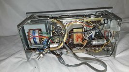
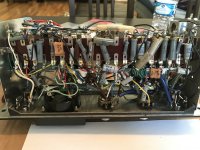
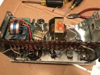
The amp arrived vai Fed-Ex yesterday and all appears as advertised in the photos above . Surprisingly clean inside! No variac at home where I'll be working on this project so I'll need to go to the hardware store and get supplies to rig a dim bulb set up to power it on. It was advertised as being a working unit, but I'd rather be safe than sorry. Once I verify it's in working order I will drain all the caps and begin labeling and removing the components to be gutted. I have my new parts on order already but they won't arrive until next week.
In the meantime I finally finished my schematic (attached below). I didn't deviate too much from the original Vox design save for the addition of a bright switch allowing lots of treble to bypass the tone knob and insert after the volume for a hopefully very bright top boost channel kind of feel. I may adjust it to insert before the volume or change the cap value if it's too much.
I may also adjust the value of C8 if things are too dark with the bright switch off. Seems like a 0.01uF might be more appropriate there to cut some low end, but I'd like to at least try the original value first.
The only other place I'm planning to make any changes will be at the tremolo circuit. I'm still undecided if I'll leave it with a set depth and adjustable speed per the Vox design or if I will try to get fancy and wire in some sort of depth control. I'm still researching this but a coaxially stacked potentiometer to control speed and depth or a 3 way switch to select varying degrees of set trem depth are both contenders at the moment.
As always all corrections, suggestions, comments or other input are welcome Otherwise I will update again once I have some more work done.
. Surprisingly clean inside! No variac at home where I'll be working on this project so I'll need to go to the hardware store and get supplies to rig a dim bulb set up to power it on. It was advertised as being a working unit, but I'd rather be safe than sorry. Once I verify it's in working order I will drain all the caps and begin labeling and removing the components to be gutted. I have my new parts on order already but they won't arrive until next week. In the meantime I finally finished my schematic (attached below). I didn't deviate too much from the original Vox design save for the addition of a bright switch allowing lots of treble to bypass the tone knob and insert after the volume for a hopefully very bright top boost channel kind of feel. I may adjust it to insert before the volume or change the cap value if it's too much.
I may also adjust the value of C8 if things are too dark with the bright switch off. Seems like a 0.01uF might be more appropriate there to cut some low end, but I'd like to at least try the original value first.
The only other place I'm planning to make any changes will be at the tremolo circuit. I'm still undecided if I'll leave it with a set depth and adjustable speed per the Vox design or if I will try to get fancy and wire in some sort of depth control. I'm still researching this but a coaxially stacked potentiometer to control speed and depth or a 3 way switch to select varying degrees of set trem depth are both contenders at the moment.
As always all corrections, suggestions, comments or other input are welcome
Otherwise I will update again once I have some more work done.Attachments
Sorry I don't know enough to be helpful. A tube rectifier is one step too retro for me, I've never used one, and never will, which is why I haven't had anything useful to contribute to this thread....pretty sure I can just use the 6X4 rectifier tube in a Vox AC4 build just fine...
-Gnobuddy
Welcome back to 1940’s/1950’s technologySorry I don't know enough to be helpful. A tube rectifier is one step too retro for me, I've never used one, and never will, which is why I haven't had anything useful to contribute to this thread.
No worries, I haven’t spent much time working with rectifier tubes either, except to change the odd one out for a friend every now and then lol, but I’m here to learn. I spent a little bit of time with the amp last evening just scoping it out and I have a few additions/changes to make to my design so there will soon be more to comment on/critic/help with for anyone who wants to
. So stay tuned, same bat channel, same bat time...Looking at your schematic a second time, I realized something: your tremolo oscillator is actually disabled (not oscillating) when the tremolo switch is in the "off" position. That seems perfectly reasonable, but I've read a few times that this type of phase-shift trem oscillator can take tens of seconds - even as much as a minute - to build up oscillations from start, and settle down to a steady state.
This, of course, means that nothing will happen when you turn the tremolo on in mid-song - at least, not for tens of seconds.
(That reminds me of a former housemate's 1982 Pontiac 6000, which, brand new, had a tragic 90 horsepower engine and 3500 lbs of curb weight; my friend's thoroughly used decade-old one probably made 60 or 70 horses at best. It was a rolling stone, but rolled so slowly it did indeed gather moss. But I digress.)
If all this is true, then you probably want the oscillator to be oscillating continuously, and the Tremolo on/off switch should just mute the tiny portion of the oscillator signal that's being fed to the input pentode. That way, you get instant response when you flip (or step on) the tremolo switch.
If the cathode follower load (100k) runs straight from cathode to ground, and you then use a coupling cap, then two 47k resistors in series to the cathode of the EF86, you should get much the same operating conditions you have now. But grounding the junction of those two 47k resistors will mute the trem signal to the EF86, while the oscillator will continue to oscillate. (I'm assuming the cathode follower is happy driving the 47k load it sees under these conditions.)
-Gnobuddy
Looking at your schematic a second time, I realized something: your tremolo oscillator is actually disabled (not oscillating) when the tremolo switch is in the "off" position. That seems perfectly reasonable, but I've read a few times that this type of phase-shift trem oscillator can take tens of seconds - even as much as a minute - to build up oscillations from start, and settle down to a steady state.
This, of course, means that nothing will happen when you turn the tremolo on in mid-song - at least, not for tens of seconds.
(That reminds me of a former housemate's 1982 Pontiac 6000, which, brand new, had a tragic 90 horsepower engine and 3500 lbs of curb weight; my friend's thoroughly used decade-old one probably made 60 or 70 horses at best. It was a rolling stone, but rolled so slowly it did indeed gather moss. But I digress.)
If all this is true, then you probably want the oscillator to be oscillating continuously, and the Tremolo on/off switch should just mute the tiny portion of the oscillator signal that's being fed to the input pentode. That way, you get instant response when you flip (or step on) the tremolo switch.
If the cathode follower load (100k) runs straight from cathode to ground, and you then use a coupling cap, then two 47k resistors in series to the cathode of the EF86, you should get much the same operating conditions you have now. But grounding the junction of those two 47k resistors will mute the trem signal to the EF86, while the oscillator will continue to oscillate. (I'm assuming the cathode follower is happy driving the 47k load it sees under these conditions.)
-Gnobuddy
First of all, that's a hilarious anecdote about that Pontiac lol
 ! Reminds me of my first car, an '89 Honda Accord with all of 125HP. It got the job done, but let's just say I never bothered engaging in any drag races after school lol.
Secondly, you're right in a way. The circuit is actually already designed to be in continuous oscillation when the amp is powered on. When ON/OFF switch closes the circuit then all the oscillation is passed to ground and we don't hear the effect. When the switch is open the oscillation effects the EF86 bias and we hear the tremolo effect. I hadn't intended for the switch to read OFF/ON, that's just the default when you select that switch symbol in KiCad, sorry about that. It's fixed now in my updated schematic posted below
Okay, I spent some more time with the unit and realized some things:
1.) I definitely have room for speed and depth knobs to control the tremolo effect so I've added a depth pot to the schematic. I believe this is the correct way to do so. It's essentially the same tremolo circuit as the old Fender 5E8A Tremolux design. If someone more knowledgeable see's something different please let me know.
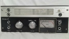
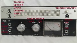
2.) The "SOUND ON SOUND" button in the upper right is an on/off switch so I'll wire that to control Tremolo ON/OFF
3.) The "STEREO/MONO" switch is basically the power on/off for this unit so I'll just re-label it to reflect this.
4.) The tone knob in place also has a speed selector that works as an on/off switch in the circuit. This is a handy place to wire in my bright switch so I'll take advantage of that
5.) The 2 inputs were already there so I went ahead and set one as a high input and the other as a low in the schematic.
Updated schematic attached and labeled photo of the face for reference to the switches and knobs mentioned above
1.) I definitely have room for speed and depth knobs to control the tremolo effect so I've added a depth pot to the schematic. I believe this is the correct way to do so. It's essentially the same tremolo circuit as the old Fender 5E8A Tremolux design. If someone more knowledgeable see's something different please let me know.
2.) The "SOUND ON SOUND" button in the upper right is an on/off switch so I'll wire that to control Tremolo ON/OFF
3.) The "STEREO/MONO" switch is basically the power on/off for this unit so I'll just re-label it to reflect this.
4.) The tone knob in place also has a speed selector that works as an on/off switch in the circuit. This is a handy place to wire in my bright switch so I'll take advantage of that
5.) The 2 inputs were already there so I went ahead and set one as a high input and the other as a low in the schematic.
Updated schematic attached and labeled photo of the face for reference to the switches and knobs mentioned above
Attachments
Last edited:
I remember Accord's of that period. They were glorious chariots of the Gods compared to my housemate's 82 Pontiac!...my first car, an '89 Honda Accord with all of 125HP...
Seriously, that Pontiac was built at about the lowest, saddest, most tragically awful point in GM's history. It was a terrible, terrible car. It handled like a sea-sick rhino in quicksand. The mechanism that raises and lowers the door glass failed in both front doors. The rear-view mirror broke off the windshield on hot days (black metal expands more than clear glass, but GM engineers didn't notice) and had to be re-glued repeatedly. The ventilation fan died, and the interior got so hot in Los Angeles that it was pretty much hazardous to life.
The one good thing you could say about that car was that the engine and transmission kept going, even when everything else failed: it remained a runner till the end, when my housemate graduated and his car went to the scrapyard.
You know, I really don't think this is the case. This is a classic phase-shift RC oscillator, which uses three RC networks in the feedback loop, each one generating roughly 60 degrees of phase shift. The total phase shift from all three stages is 180 degrees. This inverts the signal from the anode, turning it into positive feedback, which is fed to the grid. That positive feedback causes the circuit to oscillate.The circuit is actually already designed to be in continuous oscillation when the amp is powered on. When ON/OFF switch closes the circuit then all the oscillation is passed to ground and we don't hear the effect.
In your schematic, the first RC network is C10/R18. The second one is C11/R13. The third one is C12/R12. As you can see, in the "off" position, the tremolo switch shorts out R13, completely removing the feedback signal which is required to maintain oscillations. I don't see any way for the oscillator to continue oscillating with R13 shorted out.
When you flip the trem switch to the "on" position, R14 gives a little kick (positive voltage pulse) to the junction of C11/ C12 to get the oscillator started again.
The thing I don't know for sure, is how long it takes the oscillator to get going again once kick-started by R14. While I've read statements that this can take several tens of seconds, I've never built a tremolo oscillator and tried it out.
So there is the possibility that those claims are wrong. Perhaps R14 gives the oscillator a hefty-enough kick to get it oscillating fairly quickly, and this delay is acceptable to the guitarist? I know you are thorough with your research, and probably chose a circuit that's already known to work.
In any case, if you build it and it does turn out to have too much start-up delay, the fix I outlined above should work.
-Gnobuddy
I don't see any way for the oscillator to continue oscillating with R13 shorted out.
Right you are! Okay how about now? Updated schematic version 1.2 attached
That should keep the circuit in continuous osculation. The Oscillated signal goes back into the 12AX7 Grid when trem switch is open, and is redirected to ground when the trem switch is closed. Let me know if I'm still wrong, it's happened before This is really just the stock AC4 "Vibrato" circuit that came in the amp. The only change now is adjustable depth. But I haven't seen or read about any issues with it. We'll find out how I feel about it when I'm finished haha.I know you are thorough with your research, and probably chose a circuit that's already known to work.
Attachments
Last edited:
Best to leave it alone, then. If it's worked for decades now, obviously there's nothing wrong with it. I'm probably anticipating problems that don't exist.This is really just the stock AC4 "Vibrato" circuit that came in the amp.
I looked up the tremolo circuit in the '65 Princeton Reverb, and the trem oscillator is turned on and off in the same way, by stopping the oscillation outright, with a switch wired exactly the way it's wired in your VOX schematic.
Tremolo is probably also the type of effect where having it fade in over a fraction of a second might actually sound more musically appropriate than having it start right away - this would make it sound a bit more like the many, many singers who do the same thing, using tremolo only at the very end of a vocal phrase.
-Gnobuddy
Clever!4.) The tone knob in place also has a speed selector that works as an on/off switch in the circuit. This is a handy place to wire in my bright switch so I'll take advantage of that
Your Akai has a plethora of 1/4" jacks on the front panel. I could see many of them being put to good use, for example, for a footswitch, FX loop in/out, headphone jack, or line-out jack to feed to a P.A. for recording or bigger gigs.
-Gnobuddy
Your Akai has a plethora of 1/4" jacks on the front panel. I could see many of them being put to good use, for example, for a footswitch, FX loop in/out, headphone jack, or line-out jack to feed to a P.A. for recording or bigger gigs.
I agree, I'm pretty excited about how this one could turn out
If I ever get the free time to begin some actual work on it that is lol

every time I set some of the day aside for the amp something else comes up. Oh well, slow and steady is gunna have to win the race on this one I guess lol.
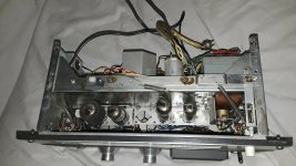
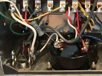
Finally got started on gutting the old circuit components the other night. Pics from right before I started removing things. When I'm done I'll have just the tubes/sockets, output and power transformers + the choke filter, and the input/output jacks I decide to keep. The 40 terminals on the fiber board should be more than enough for the simple capacitor and resistor network I'm putting in and there is ample room to work with my soldering iron .
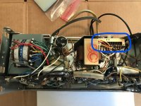
I'm thinking I'll keep all the B+ connections on top and the rest on the bottom terminals just for organizations sake. Also there is a large switching mechanism circled in blue) that is separating the EF86 & 12AX7 preamp channels as well as doing some power switching that is supposed to work in conjunction with the rest of the reel-to-reel units in the original design. That will be coming out for sure too. Right now I'm about 75% done removing old components, I'll post again once the gutting is complete and I start putting my new circuit in.
.I'm thinking I'll keep all the B+ connections on top and the rest on the bottom terminals just for organizations sake. Also there is a large switching mechanism circled in blue) that is separating the EF86 & 12AX7 preamp channels as well as doing some power switching that is supposed to work in conjunction with the rest of the reel-to-reel units in the original design. That will be coming out for sure too. Right now I'm about 75% done removing old components, I'll post again once the gutting is complete and I start putting my new circuit in.
Attachments
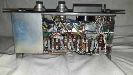
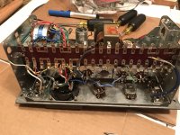
FINALLY finished removing all the old resistor and capacitor components last night. The leads were all wrapped at least 2 and occasionally 3 times around every post. I understand the importance of mechanical connection, but through the eyelet AND 3 times around the post is overkill lol 
Now I'm ready to start putting in the new caps and resistors and tiding up a few other connections and wire runs that could be done better. I hope to be done and have an update by the end of the week
Now I'm ready to start putting in the new caps and resistors and tiding up a few other connections and wire runs that could be done better. I hope to be done and have an update by the end of the week
Attachments
I agree, and incredibly frustrating if you're trying to rework a circuit....I understand the importance of mechanical connection, but through the eyelet AND 3 times around the post is overkill lol
Interestingly, when PCBs took over from turret boards and tag-strips, manufacturers stopped worrying about every soldered joint having to be twisted, looped, hooked, or otherwise mechanically connected, independently of the actual solder connection. With SMD devices, there is no longer even the option to make any sort of mechanical joint.
Looking at these examples all around me, even when I was a young boy, I stopped hooking, looping, and twisting component leads a very long time ago. I have never had any sort of failure as a result, and if I need to replace a component, life is much easier.
If you think about it, any mechanical force big enough to rip apart a good soldered joint is also, most likely big enough to damage the component itself. So if a good soldered joint comes apart, it's time to replace the component itself; knotting the wire leads in all the Boy Scout knots won't change this.
Items that are large and heavy (valves in valve sockets, non-miniature transformers, etc) certainly need to be solidly mechanically mounted - but not by the leads. Rather, by mounting screws, bolts, zip-ties, high-strength adhesive, et cetera. So, once again, hooking and looping the leads just wastes time and makes life unnecessarily difficult, with no compensating benefits IMO.
-Gnobuddy
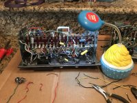
More progress and the finish line is finally in sight 

I was able to populate the whole network of new caps and resistors over the weekend and wire in almost everything else. Only 3 items left to finish out:
1. The standard size pots for my tremolo speed and depth don't quite fit in the existing holes I'd like to use for them, so I have some mini pots ordered and on the way
2. I need to wire in a switch to engage 8 ohm load resistors for when the headphone jack is in use. That was one of the many jobs done by the huge switching mechanism I chose to remove (it's many other functions where no longer necessary).
3. Final step will be wiring in the new grounded power cord and tidying up loose wires and what not. Then the amp will be ready to fire up and take for a test run
Pictures of the work in progress attached. The first one shows off my fancy cupcake work light lol. My good work light is on the fritz so I dug out the ridiculous cupcake reading light received as a gag gift last year and tossed in the back of a closet until now. It actually works very well lol
Eagle eyed viewers will also notice something else lurking in the background/periphery of both pics...
I was able to populate the whole network of new caps and resistors over the weekend and wire in almost everything else. Only 3 items left to finish out:
1. The standard size pots for my tremolo speed and depth don't quite fit in the existing holes I'd like to use for them, so I have some mini pots ordered and on the way
2. I need to wire in a switch to engage 8 ohm load resistors for when the headphone jack is in use. That was one of the many jobs done by the huge switching mechanism I chose to remove (it's many other functions where no longer necessary).
3. Final step will be wiring in the new grounded power cord and tidying up loose wires and what not. Then the amp will be ready to fire up and take for a test run
Pictures of the work in progress attached. The first one shows off my fancy cupcake work light
lol. My good work light is on the fritz so I dug out the ridiculous cupcake reading light received as a gag gift last year and tossed in the back of a closet until now. It actually works very well lolEagle eyed viewers will also notice something else lurking in the background/periphery of both pics...
Attachments
Last edited:
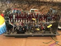
 I'm second guessing myself and need some help please to make sure I'm doing this right...
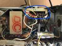
I hand drew a quick schematic for the connections needed to utilize the headphone out last night, but when I looked at my speaker out jack and realized I might be working too hard. Scan of the drawing and a pic of the speaker out jack attached:
The transformer needs an 8 Ohm load from either a speaker or a resistor if the speaker jack is not in use. The white braided lead is an 8 Ohm resistor still in place from the original circuit along with the yellow wire that runs up to the output transformer area. It looks like when there is no tip inserted into the speaker out that the tip and sleeves are connected and the the output transformer would see the 8 Ohms of resistance across both lines out just like a dummy load. The headphone out jack is just a standard stereo jack without the short when no tip is inserted.
My questions are:
1. Do I even need a switch at the transformer then or can the yellow line with 8 Ohm resistor and the normal line direct from transformer to the speaker out tip both be connected at all times? The signal would seek the path of least resistance and pass through the white line unimpeded without the yellow line causing too much extra resistance no? And when the speaker jack doesn't have a plug in, the jack shorts the tip and sleeve and the 8 Ohms of resistance is seen between them.
2. Is an additional 8 Ohms of resistance needed across the tip/ring and sleeve at the headphone out jack as well or am I okay just as the schematic is drawn here with an signal coming off the speaker out tip attenuated by a 100 Ohm resistor?
Attachments
- Status
- This old topic is closed. If you want to reopen this topic, contact a moderator using the "Report Post" button.
- Home
- Live Sound
- Instruments and Amps
- Here we go again... Akai M8 Reel to Reel Conversion