I don't think 100 ohms in series is a good way to attenuate the headphone signal - this might make the bass boomy, and the SPL from the headphones will vary widely with headphone impedance. I think it's probably safer to use two resistors to divide down the voltage before it gets to the headphones.
IMO, there are at least two other issues to consider. Firstly, and very important, headphones can very easily generate ear-damaging SPL levels. A single loud "pop" from the guitar amp might leave you with permanent hearing damage. So I think it's important to limit the maximum SPL from the headphones in some way.
Two, guitar speakers roll of all treble above 3 - 4 kHz. Headphones don't. So the overdriven tone through headphones is likely to be incredibly harsh and ice-picky, maybe even ear-damaging.
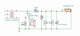
Keeping simplicity in mind, the attached image shows my suggested circuit.
The "Speaker Mute" switch lets you either keep the speaker in circuit, or replace it with an 8 ohm dummy load. The dummy load resistor should be rated at 50 watts and mounted with heat-sink grease to a metal plate to act as a heatsink; it has to safely absorb the full power output of your amp, and if it ever burns out, so will your amp!
If someday you want to monitor your amp with headphones while at the same time mic'ing the speaker, this arrangement will let you do that. Alternatively, this will let you use your headphone jack as a (crude) line out for the amp, which might be useful for recording or passing on to a P.A.
The two back-to-back 1N4148 diodes across the headphone jack are there to try to prevent permanent hearing damage caused by pops or ticks. They limit the maximum signal across the headphones to about 0.5 volts peak. With typical 32 ohm headphones with a sensitivity of 100 dB SPL @ 1 mW, this will still be ear-damagingly loud (around 110 dB SPL), but hopefully, not "blow out your eardrums" loud.
Diodes are very cheap, and your hearing very precious, so I think adding these two diodes is well worth the small extra complication. If the signal ever gets big enough for the diodes to start clipping, then the SPL at your ear is damagingly loud, and it's time to turn down the volume. At reasonable SPL, the diodes should never conduct, and so never be audible.
Finally, the 4.7 uF ceramic cap will filter out harsh treble above about 3.5 kHz. It will not filter as heavily as a proper guitar speaker, but at least it will take a little step in the right direction.
You can use an expensive film cap here if you like, but there will be zero benefits, so I'd suggest the same sort of little multi-layer ceramic cap I mentioned on your other thread. It only needs to be rated for 5 volts or more, as there is very little voltage across the actual headphone jack terminals.
I should make clear that I haven't built or tested this, so I'm taking a shot in the dark. I think it will work for you, but I can't guarantee it. Also, depending on your headphones and desired SPL and treble response, the 10 ohm resistor and / or 4.7 uF cap values might need to be tweaked to your taste.
Edit: Your amp is safe in both positions of the "Speaker Mute" switch, so it won't blow up if you accidentally forget to flip it when you plug in headphones. (However, if that switch fails to make contact, your amp is in danger. And make sure the switch isn't the "centre off" or "on-off-on" type, i.e. make sure to use an "on-on" SPST switch.)
-Gnobuddy
IMO, there are at least two other issues to consider. Firstly, and very important, headphones can very easily generate ear-damaging SPL levels. A single loud "pop" from the guitar amp might leave you with permanent hearing damage. So I think it's important to limit the maximum SPL from the headphones in some way.
Two, guitar speakers roll of all treble above 3 - 4 kHz. Headphones don't. So the overdriven tone through headphones is likely to be incredibly harsh and ice-picky, maybe even ear-damaging.
Keeping simplicity in mind, the attached image shows my suggested circuit.
The "Speaker Mute" switch lets you either keep the speaker in circuit, or replace it with an 8 ohm dummy load. The dummy load resistor should be rated at 50 watts and mounted with heat-sink grease to a metal plate to act as a heatsink; it has to safely absorb the full power output of your amp, and if it ever burns out, so will your amp!
If someday you want to monitor your amp with headphones while at the same time mic'ing the speaker, this arrangement will let you do that. Alternatively, this will let you use your headphone jack as a (crude) line out for the amp, which might be useful for recording or passing on to a P.A.
The two back-to-back 1N4148 diodes across the headphone jack are there to try to prevent permanent hearing damage caused by pops or ticks. They limit the maximum signal across the headphones to about 0.5 volts peak. With typical 32 ohm headphones with a sensitivity of 100 dB SPL @ 1 mW, this will still be ear-damagingly loud (around 110 dB SPL), but hopefully, not "blow out your eardrums" loud.
Diodes are very cheap, and your hearing very precious, so I think adding these two diodes is well worth the small extra complication. If the signal ever gets big enough for the diodes to start clipping, then the SPL at your ear is damagingly loud, and it's time to turn down the volume. At reasonable SPL, the diodes should never conduct, and so never be audible.
Finally, the 4.7 uF ceramic cap will filter out harsh treble above about 3.5 kHz. It will not filter as heavily as a proper guitar speaker, but at least it will take a little step in the right direction.
You can use an expensive film cap here if you like, but there will be zero benefits, so I'd suggest the same sort of little multi-layer ceramic cap I mentioned on your other thread. It only needs to be rated for 5 volts or more, as there is very little voltage across the actual headphone jack terminals.
I should make clear that I haven't built or tested this, so I'm taking a shot in the dark. I think it will work for you, but I can't guarantee it. Also, depending on your headphones and desired SPL and treble response, the 10 ohm resistor and / or 4.7 uF cap values might need to be tweaked to your taste.
Edit: Your amp is safe in both positions of the "Speaker Mute" switch, so it won't blow up if you accidentally forget to flip it when you plug in headphones. (However, if that switch fails to make contact, your amp is in danger. And make sure the switch isn't the "centre off" or "on-off-on" type, i.e. make sure to use an "on-on" SPST switch.)
-Gnobuddy
Attachments
Last edited:
I was thinking the same thing after looking at this closer... maybe a 68K resister between both jacks and a 3.3K resistor going to ground at the headphone out? I have plenty of both available and that should take the signal down to less than 5%I don't think 100 ohms in series is a good way to attenuate the headphone signal - this might make the bass boomy, and the SPL from the headphones will vary widely with headphone impedance. I think it's probably safer to use two resistors to divide down the voltage before it gets to the headphones.
But does the design of the original jack in place make wiring in a new switch unnecessary? That's what I'm really trying to decide.The "Speaker Mute" switch lets you either keep the speaker in circuit, or replace it with an 8 ohm dummy load. The dummy load resistor should be rated at 50 watts and mounted with heat-sink grease to a metal plate to act as a heatsink; it has to safely absorb the full power output of your amp, and if it ever burns out, so will your amp!
Also the white cloth covered resister is what was designed and put into place by the manufacturer for when the headphone jack was in use with no speaker plugged in. I haven't done anything to it and it sits in the circuit where it was put in place in 1963. It show's no signs of being burned up or excessive wear and it checks out at 7.976 Ohms of resistance on the multimeter (pretty good for a 56 year old resistor! lol) I'm thinking it must be sufficient, no? Also wouldn't a 50 watt resistor be overkill for an amp rated by the manufacturer at 6 watts peak? If I do replace the 8 Ohm resister shouldn't 10 watts suffice?
Good shout on the treble filter ideaFinally, the 4.7 uF ceramic cap will filter out harsh treble above about 3.5 kHz. It will not filter as heavily as a proper guitar speaker, but at least it will take a little step in the right direction.
 . I'm not a fan of headphone outs or line outs on a guitar amp normally for just the reasons you mentioned. It never sounds anything close to what does through a guitar speaker. Though I've had some success feeding line outs through cab sims or impulse response programs for recording.
...maybe a 68K resister between both jacks and a 3.3K resistor going to ground at the headphone out?
Unfortunately, this won't work, for a not-so-obvious reason. The two resistors will do exactly what they're supposed to do (divide down the voltage in the ratio 3.3/(3.3+68)) UNTIL you plug in the headphones. At that point, the 32 ohm (typical value) headphones will appear in parallel with the 3.3k resistor. So now the voltage divider is effectively 68k and 32 ohms...and you get only a few millivolts across the headphones, which will be far too quiet.
Looking at it a bit more technically, the problem is that a voltage divider has a non-zero output impedance. If fed from a voltage source, the output impedance is mathematically equivalent to the two resistors in parallel. In this case, 68k and 3.3k in parallel produces a 3.147k (that's 3147 ohms) output impedance - which is far too high to feed 32 ohm headphones.
The fix is to lower the resistance values, a lot. That's why I suggested 100 ohms and 10 ohms.
In the schematic you posted, if the switch is in the open position and no speaker or headphones are plugged in, there is no load at all on the amplifier output. Flames and sparks will probably ensue.But does the design of the original jack in place make wiring in a new switch unnecessary? That's what I'm really trying to decide.

If the switch is in the open position and headphones (but no speaker) are plugged in, the amp sees a roughly 132 ohm load. Sparks and flames are once again likely.

If the switch is in the open position and both speaker and headphones are plugged in, both will make sound. (Maybe you wanted this?)
If the switch is in the closed position and the speaker is plugged in, the amp sees a 4 ohm load - half of what it's expecting. It may be okay with this, but it's a bit of a gamble.
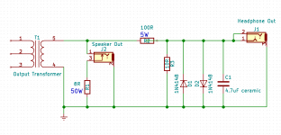
If you can replace the speaker out jack with a switching jack, then I think it's possible to do what you want without the separate speaker...schematic attached.
I agree, that sounds good. You can re-use that existing resistor, since clearly it can cope with the heat. (Betcha the white cloth is actually an insulator to keep nearby stuff from being burned. Betcha it's actually asbestos cloth...do not handle, do not breathe with your nose next to it....white resister...was put in place in 1963...no signs of being burned...checks out at 7.976 Ohms
 )
)I've found power resistor ratings to be rather, shall we say, optimistic. In my experience a 10W resistor will get hot enough to burn paper if you put 10 watts through it! So my rule of thumb is to use a resistor rated for triple the power that it will actually have to dissipate.Also wouldn't a 50 watt resistor be overkill for an amp rated by the manufacturer at 6 watts peak? If I do replace the 8 Ohm resister shouldn't 10 watts suffice?
I didn't know the output power of your Akai, and guessed at 10 watts. That would need a 30 watt resistor (unavailable). You could use a 25 watt one (marginal) or a 50 watt one (safe, and costs pennies more than the 25 W one. So I picked the 50 W one.
One of the long queue of backed-up projects in my head is to build an analogue cab-sim into a stomp-box enclosure. I know you can buy something like this, but they are too expensive for my current hobby budget.I've had some success feeding line outs through cab sims or impulse response programs for recording.
If you want a proper line-out, it should include a transformer to break ground-loops and provide a balanced output. This is quite easy to do, if you want - I designed and built one for the amp I built for a friend, and it worked very well. (Still needs a cab sim, as you say.)
Here's version 2 of the headphone out, this time using a switching jack for the loudspeaker. (So no separate switch.)
-Gnobuddy
Attachments
Last edited:
Sorry, but I made a mistake in that schematic. R2 was supposed to be 330 ohms, not 100 ohms. I typed in 100 ohms as a placeholder value while drawing the schematic, and then forgot to calculate the proper value and update the schematic.Here's version 2 of the headphone out...
With the increased value (330 ohms) and only 6 watts from the power amp (about 7 volts RMS max), R2 can be a half-watt resistor (doesn't need to be rated at 5 watts.)
I found it frustrating to repeatedly have to order one or two resistors or capacitors for projects as they evolved, and that leads to the next slippery slope: building up small stocks of the components you're most likely to need.
Something like this resistor "kit" can come in very useful (1/2 W is necessary for most valve circuits, as 1/4 w resistors have inadequate maximum voltage ratings for use as anode load resistors, etc.): Amazon.com: Joe Knows Electronics 1/2W 86 Value 860 Piece Resistor Kit: Toys & Games
There will be values you probably will never use, but it still beats paying several bucks each time you have to have a fifty-cent resistor shipped to you. (This is one of many reasons why us older electronics hobbyists miss the days of local electronics shops and even Radio Shack stores.)
-Gnobuddy
That may indeed be the best solution to dummy proof it, or save it from accidental misuse, good call!If you can replace the speaker out jack with a switching jack, then I think it's possible to do what you want
Ha ha, I'd figured as much myself. It could also be a Teflon/fiber glass cloth combo as well... both of those products we're in high use during the 60's, though the asbestos would have been much cheaper so that would be a better bet. Fortunately it's a very small resistor and probably not too dangerous. I've been around asbestos brake pads during vintage car restorations and asbestos fiberglass in very old home remodels and in those much larger quantities that stuff is bad news. We took pretty extreme precautions to not allow skin contact or breathing during those instances. Crazy to think back on all the uses asbestos had before is negative unintended effects became apparent. All the horror stories about actors being covered in it when it was used for fake snow in movies and such.I agree, that sounds good. You can re-use that existing resistor, since clearly it can cope with the heat. (Betcha the white cloth is actually an insulator to keep nearby stuff from being burned. Betcha it's actually asbestos cloth...do not handle, do not breathe with your nose next to it. )
Did you know there is supposed to be a cab sim built into our Joyo American sound pedals. Or at least according to the manufacturers website there is... could be worth taking the pedal apart and trying to trace out the cab sim circuit on the pcb board to figure it out. Or maybe even buy a second pedal to salvage parts from and design you own circuit with.One of the long queue of backed-up projects in my head is to build an analogue cab-sim into a stomp-box enclosure. I know you can buy something like this, but they are too expensive for my current hobby budget.
Okay, I'd wondered. The math makes more sense now and lines up with what you wrote in your replySorry, but I made a mistake in that schematic. R2 was supposed to be 330 ohms, not 100 ohms. I typed in 100 ohms as a placeholder value while drawing the schematic, and then forgot to calculate the proper value and update the schematic.
I'd been looking at some things just like this lately. Definitely worth the investment I'd say.Something like this resistor "kit" can come in very useful
I do miss radio shack as well, I spent time there long before I came into modifying electronics and amplifiers. Fortunately I do have a large retailer called Fry's Electronics in Houston. They don't have every resistor value but they do have a lot of them so I can drive out and buy something that will work that same day if I'm in a pinch.There will be values you probably will never use, but it still beats paying several bucks each time you have to have a fifty-cent resistor shipped to you. (This is one of many reasons why us older electronics hobbyists miss the days of local electronics shops and even Radio Shack stores.)
When I was a kid, people used to use corrugated sheets made of asbestos mixed with cement for all sorts of light-duty construction. Sheds, roofs, etc. The sheets would crack or break under sharp impact, exposing soft fluffy asbestos fibres at the new edges. I remember picking up broken pieces of the stuff and playing with it. Nobody around me knew the stuff was dangerous, and neither did I....I've been around asbestos...
Yikes!...actors being covered in it when it was used for fake snow...
I hadn't heard about that, but I remember watching a documentary film showing American soldiers spraying people (Vietnamese, I think) with DDT to help control lice infestation. Soldiers and civilians were both covered in DDT - hair, face, body, everywhere.
I've read that too, but if there is one, it isn't very apparent to my ears.Did you know there is supposed to be a cab sim built into our Joyo American sound pedals.
Sometimes I don't feel like hauling an electric guitar amp to jams (along with the Acoustic AG30, my guitar, mics, mic stands, mixer, cables, music stand, guitar stands...), and just play an electric guitar through the AG30 instead. That's when I really want the cab simulation...the AG30 has a very extended and relatively flat treble response, exactly what you want for vocals or keyboards, but exactly what you don't want for e-guitar!
There is also a cab sim in my Digitech Trio+, and at jams, I sometimes use it only for this reason. Thing is, it takes up a fair bit of pedalboard space, and needs its own power supply too. It works very well to tame excess treble from the e-guitar + AG30 combination, though.
I also have a Zoom G3, which also has (switchable) cab simulation. But I'm not a fan of the way it sounds. Somehow the G3 seems to suck a lot of the life out of my guitar sound, and leaves me with ear-fatigue if I listen to it for long.
The G3 usually lives in my closet for a year or two at a time, then I think "Time to try it again!" and haul it out for a few days, only to end up putting it back in the closet again.
I loved Fry's! It was practically my Mecca. Ridiculously huge, ridiculously well stocked, ridiculously themed, and a case of utterly ridiculous excess, capitalistic consumerism gone quite, quite mad. But so much fun to visit!a large retailer called Fry's Electronics...
There were three Fry's locations within reasonable driving range of my old home in Los Angeles county - one to the east in the City of Industry, one north-west in Burbank, and one quite a long way west in Fountain Valley.
From 2000 to 2012 or so I always built my own PCs, usually with parts on sale that week at Fry's. Between my wife and myself, I probably built over a dozen of them. PC hardware got so much faster every year back then, and the software so much slower, that you had to upgrade pretty regularly.
In 2001 I switched to Linux, and the scramble to update my PC hardware slowed down a lot after that. Add in the much slower pace of PC hardware development nowadays, and our circa-2012 hardware is still entirely adequate.
But I still miss those visits to Fry's, with a rolled-up copy of the newest Fry's newspaper ad in my hand, trying to track down the motherboard or RAM or hard-drive sale of the week.
-Gnobuddy
Somewhere I recently posted a compendium of links to cab/speaker simulation projects. But where?That's when I really want the cab simulation...


Anyway, as usual, RunOffGroove have a stompbox called the Condor which should do the job.
General Guitar Gadgets has one that Marshall apparently built into some of their products: http://www.generalguitargadgets.com/pdf/ggg_ssim_m_sc.pdf
I put that schematic into LTSpice and studied it a bit to see what frequency response it produced. Then I did a clean-sheet re-implementation, but made it adjustable, with separate pots for bass "hump" and treble rise.
If the LTSpice simulation is correct, it should be possible to dial in everything from a pretty flat frequency response to one with a bass hump, a dip above that, a slow rise to a peak at around 3.5 kHz, and a steep fall above that. Hopefully there will be something good-sounding among them.
The catch is that it uses enough components to make me tired just looking at the schematic. I've been too lazy to actually build it!
-Gnobuddy
Anyway, as usual, RunOffGroove have a stompbox called the Condor which should do the job.
Both projects have quite a lot tedious of pcb board populating, especially when sized small enough to fit in a stomp box... Definitely not a quick weekend kind of project, but interesting for sure!General Guitar Gadgets has one that Marshall apparently built into some of their products: 404 Not Found | General Guitar Gadgets ....
....The catch is that it uses enough components to make me tired just looking at the schematic. I've been too lazy to actually build it!
I don't have need for an analog cab sim pedal, but I'm filing both of these schematics away in case future need calls for it I actually have a G3N (the next generation after yours) on a pedal board. I mostly use it for the delay and modulation effects, it does a really good job of those and will run 4-7 of them at one time per programmable patch, which allows me all the sound combinations I could need and takes up a lot less space/power. Though I will say the amp and cab sims, while not the best on the market, are much more usable than I'd anticipated. The trick is spending the time to set them up so they sound believable enough, it takes some tweaking and every cab sim seems to respond differently than the next to the same adjustable perimeters. Not sure how the G3 differs... the G3N allows adjustment between a directional mic and ribbin mic response and also allows for some mic placement adjustment to accentuate or back off high and low frequencies. Does the G3 give you these same adjustments?I also have a Zoom G3, which also has (switchable) cab simulation. But I'm not a fan of the way it sounds. Somehow the G3 seems to suck a lot of the life out of my guitar sound, and leaves me with ear-fatigue if I listen to it for long.
The G3 usually lives in my closet for a year or two at a time, then I think "Time to try it again!" and haul it out for a few days, only to end up putting it back in the closet again.
No, but you can choose between "It sucks a little" and "It sucks a lot"!Does the G3 give you these same adjustments?
I'm probably not being entirely fair to the G3. The built-in looper and (incredibly bad-sounding) drum-machine have been very useful for guitar practice, at least in the years before I got my Digitech Trio+. I've used a couple of the G3's reverbs and they varied from okay to good. There is an incredible amount of stuff packed into one little box, for sure.
All this is why I pull it out of the closet every so often. A few days later, sick of seemingly endless knob-twiddling and parameter tweaking without ever coming close to the sounds in my head, I stuff it back.
For me, the G3 isn't actually bad. It isn't actually good, either. And that's the frustrating part - it's sufficiently not-bad to keep me convinced that if I just tinker with it some more, it will sound great. But it never does.
Maybe I'd be a lot happier with the G3 if I ran it into a really good-sounding valve guitar amp. In the meantime, it continues to tantalize me with possibilities that always seem to remain just out of reach.
As a person interested in solid-state electronics, the G3 is intellectually frustrating to me, too. At first sight it seems to have all the right ingredients, with billions of transistors, high quality A/D and D/A converters, fast and powerful DSP chips, and solid engineering. Then my ears say that all this wonderful technology just doesn't sound as good as a couple of primitive vacuum triodes in an eighty-year-old preamp circuit, and I don't really know why. Arrgh!
We've never talked about this, but I'm not one of those people who universally hates all things digital. When I heard my first audio CD, I was blown away by how much better it was than every form of consumer audio that came before it. At one stroke it eliminated all the frustrating problems I'd suffered for years: wow, flutter, rumble, inaccurate and limited frequency response, pops, ticks, hiss, record wear, tape wear, tape print-through, inadequate dynamic range, et cetera.
In college I borrowed and studied library books on the mathematics of digital audio, and understood enough of how the magic works to truly admire the genius of Claude Shannon (the first to realize that all information, including audio, could be stored and manipulated digitally), and the numerous others who brought us practical and affordable digital audio.
So it's not that I hate affordable digital guitar amps and processors on principle. I've tried a lot of them over the years, and to my ears, most of them simply don't sound good. Some (like the the Line 6 Pod and the two awful Line 6 Spyder amps I owned at various times) sound outright horrid.
The Boss Katana 50 and 100 might change my mind, but I haven't heard them in person yet.
-Gnobuddy
I don't hate digital modelers either, cheap or expensive. Though you're not wrong when you say that a great many of them over the years have not been good lol. I've played and seen some Helix / Kemper / AXE FX modelers that are indeed very good. In a blind test listening to recording or in the crowd I don't think there's any way to tell the difference with these anymore. And the cheaper units, while not there yet, are getting better every year. But still there's a subtle charm that lies in "old things". Be they automobiles, record players, old tube amps, etc. Newer products do the same jobs more efficiently, cheaply, quickly, and often times perform better, but still there's just something a lot of us love about, "that great old ____" that's hard to explain.So it's not that I hate affordable digital guitar amps and processors on principle. I've tried a lot of them over the years, and to my ears, most of them simply don't sound good.
Speaking of old things, and more related to the thread topic lol... (I really don't mind these tangents at all during down periods in my project post/questions, they keep things interesting
)I wired in my mini pots for the tremolo system and bypassed the microphone output for the time being to take the amp on its first test run last night and...
***** Drum roll to build exitement *****
We've got trouble lol

I'd already tested the unit before conversion to assure both transformers checked out, and had a nice strong output. But when I wen't to test last night the power transformer started up right away and warmed all the tubes correctly, but I couldn't get any output to the speaker at all. Not a single hum, noise, or crackle. So either my output transformer has suddenly died completely or I've gone wrong somewhere in the circuit wiring that I'm not aware of...
I didn't have the time or energy to fully trouble shoot it last night so I'll have to do some work this weekend and hopefully come up with an easy solution, like a missed connection or poor solder somewhere. I'll post more when I know more. Wish me luck haha
Sorry to hear it! In my experience, this is more the norm than the exception. Whether software or electronics, there's usually some debugging involved before it works as intended. As long as you're methodical and proceed logically, you will find and fix the fault.We've got trouble lol
Good, the heater wiring and power supply is working.warmed all the tubes correctly
With mains power off, amp unplugged, and all power supply caps fully discharged, I would start with the speaker, and work back. Does your DMM show continuity at the speaker terminals? At the 1/4" plug you're using on the speaker lead?but I couldn't get any output to the speaker at all.
How about the OT secondary (speaker side)? Is there continuity across the speaker output jack?
Now the OT primary (remember, amp unplugged, all power supply caps discharged, zero volts B+ before you touch anything in the amp.) Set the DMM to a suitable fairly low ohms range (maybe 2k). Measure resistance across the OT, end to end for SE, centre tap to each end for PP. Are the numbers reasonable? A few tens of ohms is normal, maybe a couple of 100 ohms if it's a very small high-Z transformer, but it shouldn't be higher than that.
All good so far? Put some clip-leads on a 9V flat battery, touch the leads across the OT primary. You should hear crackles in the speaker. If not, investigate, fault-find, repair, or replace, until you do.
Next up, resistance checks from the valve socket. You should get near-zero resistance from the valve anode(s) to the appropriate OT terminals. Also near-zero resistance from B+ to appropriate OT terminal.
Use the DMM to measure from screen grid tag on the valve socket to B+. Your DMM should show the appropriate value corresponding to whatever screen grid resistor(s) you're using.
Now check control grid to ground. It should match the sum of your grid-stopper plus grid bias resistor.
If the suppressor grid has a separate pin of its own, check resistance from there to valve cathode; it should be zero resistance. Fix if necessary.
Check resistance from cathode to ground. Does it match the value of the cathode resistor, if any (cathode bias)?
Once all these checks are passed successfully, it's time to apply power again. If you have already found and fixed one or more faults to get to this point, you may now find the speaker is making noises.
If not, it's time to either hand the amp to a tech, or start the dangerous business of measuring lethal voltages in a live amp. I use electricians class 0 (class 00 is okay too) gloves on my hands, and wear eye protection in case of sparks and white-hot metal fragments. Gloves: Class 00 Electrical Insulating Rubber Gloves - 14 inch
Make sure the chassis is securely supported. Make sure you're sitting on an insulating surface, electricians safety gloves and eye-protection on. Clip the ground wire of your DMM securely to a grounded point of the circuit - chassis, solder tag, turret.
Now, very carefully to avoid accidental shorts, sparks, and exploding components, measure DC voltage at both ends of the OT, at the output pentode anode(s), screen grid(s), control grid(s), and cathodes.
If all those voltages are normal, and your amp has already passed all the previous resistance checks, the output stage and speaker should be alive and working. You should hear faint hum, and touching the output pentode control grid with a DMM probe should make crackling or scratching sounds in the speaker.
Still no guitar signal? Power off, drain filter caps, start with the resistance checks in the driver stage, the one that drives the output pentode. All resistance checks passed? Time to do the DC voltage checks on that stage.
And so on, all the way back to the input jack if necessary, by which time you will hopefully have found and fixed the problem.
I have seen problems that are not revealed by either resistance or voltage checks, (such as a capacitor that has a loose wire lead inside it's housing, so it effectively has near-zero capacitance), but they are rare. With a little luck, you won't be dealing with one of these!
Nostalgia is a very real thing, sure. But valves were already dead and gone when I was born! If anything, I should be nostalgic for the germanium diodes and transistors I used when I first got interested in electronics, somewhere between seven and eight years old. Maybe for the discrete silicon epitaxial transistors I came to love a few years later, because they worked so much better than the leaky and fragile germanium ones.Newer products do the same jobs more efficiently, cheaply, quickly, and often times perform better, but still there's just something a lot of us love about, "that great old ____" that's hard to explain.
Valves were never on my radar when I was young - all I knew was that they were extinct, a part of early electronics history, and they had been replaced by semiconductors because the latter were far superior in every way. I built tons of circuits with transistors, and later, integrated circuits. They were wonderful - radios, cassette decks, turntables, power amps, Dolby noise-reduction circuits, all of them.
But there was one ugly exception. I began playing electric guitar in my twenties, and I sounded horrible. Decent on an acoustic guitar, horrid with an electric. I built half a dozen guitar amps, all solid-state. All sounded horrid. I bought affordable solid-state amps by the likes of Fender. They were horrible.
Twenty years later, still sounding horrid every time I picked up one of my electric guitars, I was now out of college and had a job. I made enough money to buy a Line 6 Spyder II (around $300 - 350 US, not cheap.) It was horrible. I tried a Line 6 POD - horrible. Line 6 Spyder Jam - utterly horrible.
I was this close to giving up e-guitar for good, but the Internet now existed, and I discovered guitar forums online. Lots of people believe valve guitar amps sound better? They must be nuts, everyone knows valves are primitive and went extinct. But there was this hybrid amp called a Super Champ XD that had valves in its power amp section, and lots of people really liked it.
So, for another $300 USD, I bought one, took it home, plugged in, turned on, waited 30 seconds, and strummed my guitar. And my mouth fell slackly open, as for the first time in my life, an electric guitar in my hands sounded good.
That was when I discovered that all my problems with horrible e-guitar tone for 20 years had been caused by the solid-state guitar amps I'd been using. How the heck did I not know this sooner?
So: I don't love valves. I think valves for Hi-Fi are ridiculous - Hi-Fi is about precise and accurate, and solid-state is far better at that. (Especially digital solid-state.)
But e-guitar, particularly solid-body e-guitar? The instrument itself sounds lousy. Primitive distorting valves mangle the guitar signal and somehow make it sound much, much better. Analogue solid-state amps don't do this, they just reproduce the lousy sound of the instrument itself. Digital solid-state amps try, but the affordable ones certainly haven't gotten it right yet.
I will buy digital/DSP guitar amps when they sound at least as good as this cheaply made $200 USD valve amp: YouTube
Some day they will, but that day isn't here yet. (And the big companies have been trying for well over thirty years now.)
-Gnobuddy
Nice order of operations, thank you! I generally know what to test for but your check list has a pretty pragmatic and well thought out order of someone with experience, so I gladly followed it . I was only able to work on the amp for 35 mins or so this weekend till some other things came up, but here's how far I was able to get with my multi meter in that short time...

 marked to return to this when I have time. More on this later in the post as well...
This is as far as I got in my limited time over the weekend. I do have a couple additional thoughts and questions below:
1. I also checked individually from the primary OT terminals to ground to make sure we didn't have an internal short to ground in the transformer. This checked out okay, no reading up to 2M so sufficiently insulated from ground on the primary side.
I wasn't able to make the same check on the secondary as the - terminal was grounded to the OT case by the manufacturer. (again this is consistent across all three OT's in my possession)
2. The good news is it's starting to look like the OT transformer is not the issue here. I do realize there are other OT issues that can't be tested with a multi meter, but the fact that it's passed all these tests so far is a good sign for the OT at least
3. On the failure to get a reading from the control grid to ground: I want to go back and triple check this to make sure it wasn't a fault of my own, but at the time I was not able to get a reading from the grid stopper resistor to ground or from the grid pin to ground. And I did try a few other ground points aside from the point where the cathode bias is grounded, though I did not have an issue measuring from the cathode pin to the cathode bias ground point just before this. It sure looks like the failure lies in the tube itself or in the tube receptacle/pins. I'll be looking here next when I get the chance.
Would it be possible for the control grid inside the tube to be compromised but the tube still light up and show no discoloration, cracking, or other signs of failure? Or is it much more likely for the pin to the control grid in the tube receptacle to be compromised? Obviously I will check for both, just curious if your experience inclines you to suspect one possibility before the other.
I will be checking out the EL84 tube receptacle at first opportunity, and also swapping out the current EL84 tube for another. I'm pretty sure that's going to solve the issue, so it doesn't look like I will be progressing on to testing on the amp while powered. Of course this could be considered counting the proverbial chickens before they hatched... we shall see lol. At any rate, a quick word on me if the occasion does call for it: I once upon a time worked (for several years) as a licensed electrical sign technician, so I'm not squeamish working with and around dangerous voltages, and I also still posses some of my old tools and safety equipment used for these purposes. I do appreciate your wise words of warning and safety recommendation though. Every bad electrical accident begins with someone who is too comfortable or complacent in the work they're doing, and then in an instant *spark* *zap* ! Or maybe worse
  No one want's that, especially when precautions can be take to avoid it!
. I was only able to work on the amp for 35 mins or so this weekend till some other things came up, but here's how far I was able to get with my multi meter in that short time...With mains power off, amp unplugged, and all power supply caps fully discharged, I would start with the speaker, and work back. Does your DMM show continuity at the speaker terminals? At the 1/4" plug you're using on the speaker lead?
How about the OT secondary (speaker side)? Is there continuity across the speaker output jack?
SE OT so end to end resistance was 453 Ohms. I initially though this might be a little high, but when I tested across terminals on my 2 other identical working Roberts units with the same OT I got very similar values (451 Ohms & 454 Ohms). Additional internet research proved this seems to be standard on this particular OT model.Now the OT primary (remember, amp unplugged, all power supply caps discharged, zero volts B+ before you touch anything in the amp.) Set the DMM to a suitable fairly low ohms range (maybe 2k). Measure resistance across the OT, end to end for SE, centre tap to each end for PP. Are the numbers reasonable? A few tens of ohms is normal, maybe a couple of 100 ohms if it's a very small high-Z transformer, but it shouldn't be higher than that.
Battery test was positive on the first try.All good so far? Put some clip-leads on a 9V flat battery, touch the leads across the OT primary. You should hear crackles in the speaker. If not, investigate, fault-find, repair, or replace, until you do.
zero resistance for both values, these are very short wire runs on this amp.Next up, resistance checks from the valve socket. You should get near-zero resistance from the valve anode(s) to the appropriate OT terminals. Also near-zero resistance from B+ to appropriate OT terminal.
No screen grid resistor in this design, I wanted to try the original Vox circuit as it was designed before meddling with anything (aside from the addition of the trem depth control) This measurement was essentially a repeat from the above, zero resistanceUse the DMM to measure from screen grid tag on the valve socket to B+. Your DMM should show the appropriate value corresponding to whatever screen grid resistor(s) you're using.
Couldn't get a reading hereNow check control grid to ground. It should match the sum of your grid-stopper plus grid bias resistor.
marked to return to this when I have time. More on this later in the post as well...These are tied internally inside the EL84 tubeIf the suppressor grid has a separate pin of its own, check resistance from there to valve cathode; it should be zero resistance. Fix if necessary.
Yup 150 Ohms on the nose, all good here.Check resistance from cathode to ground. Does it match the value of the cathode resistor, if any (cathode bias)?
This is as far as I got in my limited time over the weekend. I do have a couple additional thoughts and questions below:
1. I also checked individually from the primary OT terminals to ground to make sure we didn't have an internal short to ground in the transformer. This checked out okay, no reading up to 2M so sufficiently insulated from ground on the primary side.
I wasn't able to make the same check on the secondary as the - terminal was grounded to the OT case by the manufacturer. (again this is consistent across all three OT's in my possession)
2. The good news is it's starting to look like the OT transformer is not the issue here. I do realize there are other OT issues that can't be tested with a multi meter, but the fact that it's passed all these tests so far is a good sign for the OT at least
3. On the failure to get a reading from the control grid to ground: I want to go back and triple check this to make sure it wasn't a fault of my own, but at the time I was not able to get a reading from the grid stopper resistor to ground or from the grid pin to ground. And I did try a few other ground points aside from the point where the cathode bias is grounded, though I did not have an issue measuring from the cathode pin to the cathode bias ground point just before this. It sure looks like the failure lies in the tube itself or in the tube receptacle/pins. I'll be looking here next when I get the chance.
Would it be possible for the control grid inside the tube to be compromised but the tube still light up and show no discoloration, cracking, or other signs of failure? Or is it much more likely for the pin to the control grid in the tube receptacle to be compromised? Obviously I will check for both, just curious if your experience inclines you to suspect one possibility before the other.
I will be checking out the EL84 tube receptacle at first opportunity, and also swapping out the current EL84 tube for another. I'm pretty sure that's going to solve the issue, so it doesn't look like I will be progressing on to testing on the amp while powered. Of course this could be considered counting the proverbial chickens before they hatched... we shall see lol. At any rate, a quick word on me if the occasion does call for it: I once upon a time worked (for several years) as a licensed electrical sign technician, so I'm not squeamish working with and around dangerous voltages, and I also still posses some of my old tools and safety equipment used for these purposes. I do appreciate your wise words of warning and safety recommendation though. Every bad electrical accident begins with someone who is too comfortable or complacent in the work they're doing, and then in an instant *spark* *zap*
! Or maybe worse No one want's that, especially when precautions can be take to avoid it!I agree, certainly nothing obvious like a shorted or open-circuit winding.The good news is it's starting to look like the OT transformer is not the issue here.
As an aside, just a few days ago, on another diyAudio thread, I learned about a simple DIY tool for checking for shorted turns inside a transformer: The Super-Secret Transformer Tester
Could be as simple as a bad solder joint on the ground end of the grid leak resistor, or a missing ground wire to that tag, or a bad (open-circuit) grid stopper or grid bias resistor....I was not able to get a reading from the grid stopper resistor to ground or from the grid pin to ground.
A few checks with the ohmmeter should reveal which, if any of these, is the problem.
There have been a couple of times in the early years when I managed to make a solder joint that looked fine, but in which one wire completely failed to make contact, because it was covered in a thin film of oxide or soldering flux inside the joint. Since then I tin lead ends before soldering, and that pretty well prevents this problem.
If you measure from the appropriate lug on the underside of the valve socket, you can tell whether the problem is in the external resistors and solder joints. If you get a good reading at the valve socket, but not the valve pin, then that points to the valve socket itself as a suspect, assuming the valve is still inserted far enough into the socket so that it should be making good contact....or in the tube receptacle/pins...
Keeping in mind that I only have about ten years experience with valves, and not all that many of them, my guess is that it's not the control grid - they usually live sheltered lives, with very little voltage or current ever applied to them. (Screen grids live like James Bond by comparison, in constant peril, and seem to die violently at a young age in some guitar amp designs.)Would it be possible for the control grid inside the tube to be compromised but the tube still light up and show no discoloration, cracking, or other signs of failure? Or is it much more likely for the pin to the control grid in the tube receptacle to be compromised?
Corrosion on the valve socket itself is definitely a possibility, but so is a faulty solder joint to an old corroded valve socket lug. Your ohmmeter should help you figure out which one it is (and it doesn't hurt to re-flow any suspect solder joints for insurance.)
In that case, you probably know much more than I do about safety around high voltages, and I should be taking advice from you instead of the other way around....a licensed electrical sign technician...
In college, I once worked in a lab with a dangerously powerful argon-ion laser. It would burn your skin if you accidentally passed your hand or arm through the beam, and was capable of blinding you so quickly that your eye would not even have time to notice the light before you were blinded for life.Every bad electrical accident begins with someone who is too comfortable or complacent
As a constant reminder, there was a poster on the door into the lab that read "Do not look into laser with remaining eye."
We students were all cautiously afraid of the laser, and worked around it with extreme care. But I once saw an experienced faculty member staring into the optical apparatus, with a fairly bright reflected beam (bounced off a hanging mirror inside the apparatus) dancing around on his cheek.
He was about an inch and a half away from instant and total blindness, in other words, and was totally ignoring every scrap of lab safety-awareness.I plucked up my courage and told him he was in danger, and he immediately dismissed the issue with a causal claim about how he'd been working around lasers longer than I'd been alive, blah, blah.
-Gnobuddy
Nostalgia is a very real thing, sure. But valves were already dead and gone when I was born! If anything, I should be nostalgic for the germanium diodes and transistors I used when I first got interested in electronics
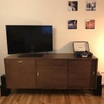
We need an English word that means; nostalgia for a bygone era, or products reminiscent of that era, even though one did not live during said era. With all the retro fashions, popular period piece TV shows and movies, not to mention classic car culture and the like, you'd think we would have come up with one by now. Sure some of this is fueled by people who have lived through these times, but I think it's safe to say that all the people showing up with old Ford Model T's and A's to car shows did not learn to drive one to pass their tests for driver's licenses. And all the people tuning in to watch shows and movies like Downton Abbey were definitely not alive in the 1910's or 1920's lol . I think a lot of us can fall victim to romanticizing some "golden age" we were never a part of, even I'm not exempt. I wasn't born yet to experience the 50's or 60's for myself, but I've always had an affinity for much of the music, fashion, furniture, and pop culture from those decades. Not that I'd want to go back an live there as opposed to my own time or some such nonsense. As a former history major I'm well aware the best "golden age" available is always the one we're living in now and taking for granted lol, but there is definitely a mid-century modern flair to my home decor. Check out the attached pic of the credenza I built from scratch 2 years ago inspired by the Dutch furniture designs of the late 1950's & early 1960's You're not alone in this for sure. I think there has been a real resurgence in guitar tube amp popularity that started around the early 2000's and was galvanized by the growth of the online culture you mentioned, as well as the boutique amp movement and some of the vintage nostalgia lust mentioned above, but the 80's and 90's were a real dry era for any amp technology that wasn't somehow tied to solid state amp building or other horrible "advances" in amp tech. Of course there were a few exceptions to this but most of the entry level and mid priced amp market was focused on making solid state work. Before this resurgence in classic tube amp design, my age group only knew to buy tube amps if they were lucky enough to have an older musician (family member, music teacher etc.) that knew better and instructed us to do so. Or if one was really lucky they got a nice old hand-me-down tube amp from someone and lucked out on something like a nicely made 70's Fender silverface of some kind, before the vintage market craze drove the price up on these to where it is now (way too high for decent amps, but nowhere near the quality of the earlier era Fenders). I myself was offered a 70's Fender Champ model, FOR FREE, from a family friend who found out I had just started playing guitar around 1995. I turned them down because the amp looked old, dirty, and couldn't possibly be as good as my brand new solid state Crate with a built in distortion foot switch (the most unpleasant and unusable distortion sound ever lol). Only years later would I learn that those little champs are some of the best practice tube amps ever made. Today you can't buy one for less than $300 and some models sell for hundreds more!That was when I discovered that all my problems with horrible e-guitar tone for 20 years had been caused by the solid-state guitar amps I'd been using. How the heck did I not know this sooner?
Oh well, live and learn haha I didn't discover tube amp glory for myself until I was wasting time in a music shop around 1999 and plugged a tele into a Vox AC-15, for lack of a recognizable solid state option. It was one of the good Vox's still made in England at the Marshal plant, before they sold the company's interests and all construction was outsourced to China, and boy did I strike gold with that combo! Suddenly all those classic rock tones came alive in my hands, and for the first time ever someone else complimented my playing as they walked by me in the store. "What kind of gypsy magic is happening in this amp!?" I wondered to myself lol. I didn't buy one that day, but I started saving up and got an old used 70's Princeton Reverb later that year. An amp I never should have gotten rid of, but that's another story...
Attachments
How about "atavistalgia", from atavism and nostalgia?
My wife binge-watched Downton Abbey on Netflix, and I watched some episodes with her....shows like Downton Abbey...
But we also talked about the grimly limited options the servants had, and the fact that much of the vast wealth the aristocrats possessed came from the blood, sweat, and tears of oppressed people: not only the serfs in Britain, but all the occupants of countries conquered and held by the British using ongoing extreme violence and frequent slaughter that lasted decades or centuries in some cases.
One of my co-workers is from the Philippines, and he talks about the ongoing cultural impact of nearly three and a half centuries of Spanish enslavement; he says his people have very little appreciation or respect for anything from their own culture, and instead look to America and Europe for ideas and things to value. Brand snobbery is severe, and it is always for non-Philippino brands.
As long as we're dreaming, I'll take my 21st-century electronics, car, and kitchen appliances, along with contemporary medical science and generally less-extreme racism and improved cultural tolerance, and move them back about seventy-fifty years to a time when BC had a lot more trees and wildlife, and a lot less concrete....I'm well aware the best "golden age" available is always the one we're living in now and taking for granted...
Nice carpentry! You're quite the renaissance man. Cute pics with your wife, too!...pic of the credenza I built from scratch...
Going by my high-school graduation date, statistically I would be expected to like late 70's through mid-80's music. But I can't stand most of the music from that era, particularly post-1983, when MIDI standardization and early sequencers arrived. Those songs are rife with awful guitar tone, awful soulless sleazy sexist lyrics, dreadful drum-machines, and almost equally dreadful sequencer-driven synth riffs. Yuck.the 80's and 90's were a real dry era for any amp technology
Yeah, that applies to me too, possibly because I learned to play guitar mostly in a vacuum, i.e., no other guitar players to learn from. (But it was the '80s, huge rack-mount electronics and horrid guitar tone were the norm, and perhaps I would have been even worse off if I had had contemporary guitarist friends to learn that from.)my age group only knew to buy tube amps if they were lucky enough to have an older musician (family member, music teacher etc.) that knew better and instructed us to do so.
Ouch. That memory probably still hurts a bit!I myself was offered a 70's Fender Champ model, FOR FREE
There was the time in the early 1990s when I nearly bought a '73 Plymouth Barracuda with the 340 V8, 4-barrel carb, and 4-speed manual transmission. I think the seller was asking $1800. There was damage to one rear quarter-panel, and as a struggling college student, I knew I would never find the money to repair it...so I passed. Ouch!
That's it exactly. It seems you had a very similar experience to mine - your hands haven't changed, but your guitar suddenly sounds better, and you can't understand why!...for the first time ever someone else complimented my playing as they walked by me in the store. "What kind of gypsy magic is happening in this amp!?" I wondered to myself lol.
I found a "Best of Bachman-Turner Overdrive" CD at a local thrift shop a few days ago, and bought it for $2, mainly out of curiosity about the famous Garnet Herzog, a Fender Champ turned guitar preamp, thanks to Randy Bachman's idea and Gar Gillie's amp-building skills.
While most guitar aficionados are familiar with the sound of "American Woman", what really intrigued me were some of the nearly clean-tone guitar solos elsewhere on the CD. Those nearly-clean tones were gorgeous, at least to my ears. Very "valvey" or "tubey", for lack of a better word, lush and rich and sparkling.
I speculate that this has something to do with the sheer number of valves the signal had to pass through in Bachman's setup.
The Herzog was basically a Champ, so it had two triodes and a 6V6 beam tetrode in it, followed by heavy signal attenuation to bring it back down to instrument level.
The Herzog was plugged into a custom guitar amp that Gar Gillies designed and built, and I can't find any details about it. But my guess is that it followed the general topology of Fender amps of the time - two triodes in the preamp, one more triode in the phase splitter, and then push-pull beam tetrodes at the output.
(Bachman was quoted as saying he also used an actual big Fender amp, but didn't say which one; it probably had a similar topology, unless it was a Bassman with the extra cathode-follower stage.)
So the guitar signal chain would probably have been triode -> triode -> beam tetrode -> triode -> triode -> triode -> beam tetrode before it reached the speaker. Seven valve stages in all, each adding its own layer of subtle harmonics and distortion.
I, like most of us guitarists, have never played through an amp with more than five cascaded valve stages in it. Most have had only four. My Super Champ XD has only three...the gain stage, cathodyne, and output stages in the power amp. The cathodyne doesn't count, with its heavy local negative feedback it is solid-state clean, and makes no audible "valvey" distortion.
I'm going to have to try six or seven cascaded stages in an amp some day...some of Bachman's clean and slightly overdriven tones sounded too good to ignore!
-Gnobuddy
Quick update since it's been quite a bit since my last one.
I figured out there was an issue in the EL84 tube socket, I believe with pin 3 which is the cathode. The after narrowing it down to the socket alone and not the tube itself I started work in removing the socket for repair or replacement. The sockets are all riveted in on this amp so it took some prearranged reorganizing and safety precaution to cover and protect the rest of the amp from metal shavings before I started drilling. I couldn't do anything to save the socket, the pin inserts are not removable on the socket and it's just too tiny to work inside the pin holes to see if there was an obstruction to be cleared or another fixable problem. Unfortunately the original has to be the smallest tube socket diameter I've ever seen . It's barely wider than the pin holes. As a consequence of this I tried 3 different brands of socket with no success fitting the tiny existing socket hole. So I had to drill out the hole to fit a new socket and measure out new holes to bolt the socket it, then realize that no matter how I arranged it there was only enough room for 1 bolt and nut to be properly inserted and threaded before running out of room to work in the second one. So more time was taken to properly secure the socket in well enough that it remains secured to the chassis whilst removing a tube from it. I'm hoping to re-solder the socket connections soon and that there aren't any other major issues to suss out. I'll update again once that's all done.
I figured out there was an issue in the EL84 tube socket, I believe with pin 3 which is the cathode. The after narrowing it down to the socket alone and not the tube itself I started work in removing the socket for repair or replacement. The sockets are all riveted in on this amp so it took some prearranged reorganizing and safety precaution to cover and protect the rest of the amp from metal shavings before I started drilling. I couldn't do anything to save the socket, the pin inserts are not removable on the socket and it's just too tiny to work inside the pin holes to see if there was an obstruction to be cleared or another fixable problem. Unfortunately the original has to be the smallest tube socket diameter I've ever seen
. It's barely wider than the pin holes. As a consequence of this I tried 3 different brands of socket with no success fitting the tiny existing socket hole. So I had to drill out the hole to fit a new socket and measure out new holes to bolt the socket it, then realize that no matter how I arranged it there was only enough room for 1 bolt and nut to be properly inserted and threaded before running out of room to work in the second one. So more time was taken to properly secure the socket in well enough that it remains secured to the chassis whilst removing a tube from it. I'm hoping to re-solder the socket connections soon and that there aren't any other major issues to suss out. I'll update again once that's all done.Don't you love the way those ten-minute tasks so often turn into ten-hour ones?...no matter how I arranged it...
Mr. Murphy has far too much fun at our expense!
-Gnobuddy
Quick update for anyone following along with my faithful friend Gnobuddy
Help needed please lol
I’ve finally had a little free time to work on the amp, here is what I know:
All of the wiring and connections are good, I’ve checked them each 10 times now.
The power transformer is good.
New tubes in all sockets and they all light up when powered on.
Still no output to speaker at all, not even a single hum or crackle.
But the output transformer passes every test I’ve thrown at it. For example all measurements I take from it are correct, and when placing a 9V battery between the output transformer’s primary terminals I do get a crackle from the speaker. So I’m pretty sure it’s working.
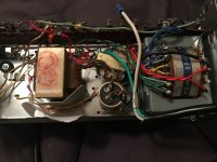
The one area I’m beginning to wonder about now are the capacitor can and choke filters in the attached photo. Both sit in the circuit between the output transformer and the incoming B+ power. The cap can has 2 x 20 mfd capacitors inside that are original to the Akai unit and have not been replaced. The choke filter is original to the unit as well and not inherent to the AC4 design but I thought it couldn’t hurt to leave it in. However it occurs to me that if one or both of these items is failing that could interrupt voltage to the output transformer and explain the symptoms my amp is exhibiting.
Anyone have any thoughts on if my thinking is possibly correct, and how should I go about testing to see if either the capacitors in the can and/or the choke filter are failing? Hoping there is a way to test them in the circuit but I can remove them without too much trouble if necessary.
Help needed please lol
I’ve finally had a little free time to work on the amp, here is what I know:
All of the wiring and connections are good, I’ve checked them each 10 times now.
The power transformer is good.
New tubes in all sockets and they all light up when powered on.
Still no output to speaker at all, not even a single hum or crackle.
But the output transformer passes every test I’ve thrown at it. For example all measurements I take from it are correct, and when placing a 9V battery between the output transformer’s primary terminals I do get a crackle from the speaker. So I’m pretty sure it’s working.
The one area I’m beginning to wonder about now are the capacitor can and choke filters in the attached photo. Both sit in the circuit between the output transformer and the incoming B+ power. The cap can has 2 x 20 mfd capacitors inside that are original to the Akai unit and have not been replaced. The choke filter is original to the unit as well and not inherent to the AC4 design but I thought it couldn’t hurt to leave it in. However it occurs to me that if one or both of these items is failing that could interrupt voltage to the output transformer and explain the symptoms my amp is exhibiting.
Anyone have any thoughts on if my thinking is possibly correct, and how should I go about testing to see if either the capacitors in the can and/or the choke filter are failing? Hoping there is a way to test them in the circuit but I can remove them without too much trouble if necessary.
Attachments
- Status
- This old topic is closed. If you want to reopen this topic, contact a moderator using the "Report Post" button.
- Home
- Live Sound
- Instruments and Amps
- Here we go again... Akai M8 Reel to Reel Conversion