I've been experimenting with making low-power guitar amps using subminiature, direct heated tubes. I've gotten to a design that sounds decent and can produce reasonable bedroom practice volumes, and I figure this is a good point to stop and solicit some feedback.
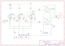
What I have is two 6088 gain stages, a 6088 anode follower paraphase inverter, and two 5672s in push-pull. Originally I had two parallel 5672s operating SE, but I find the PP setup can get a clean sound at a slightly louder volume. All tubes of the same type have their filaments in parallel, and they tap a series chain of tubes, resistors, and diodes to get the desired voltages for bias. The output transformer is a Hammond 125A.
The power supply, not shown in the schematic, is currently a 44v CT transformer, bridge rectified to produce 60vdc, 30vdc pulled from the center tap, and then an arrangement of two LM317 regulators producing 45v and 7.15v.
Please note, this is my first foray into tube amps, and I only just started learning about analog electronics a few months ago, so I may well be confused about a great many things. Also please excuse my schematic skills — this is my first one!
Some questions:
Next I'm thinking about switching the gain stages to 5678s, since I think those can get a bit louder than 6088s.
Any thoughts or suggestions would be appreciated!
What I have is two 6088 gain stages, a 6088 anode follower paraphase inverter, and two 5672s in push-pull. Originally I had two parallel 5672s operating SE, but I find the PP setup can get a clean sound at a slightly louder volume. All tubes of the same type have their filaments in parallel, and they tap a series chain of tubes, resistors, and diodes to get the desired voltages for bias. The output transformer is a Hammond 125A.
The power supply, not shown in the schematic, is currently a 44v CT transformer, bridge rectified to produce 60vdc, 30vdc pulled from the center tap, and then an arrangement of two LM317 regulators producing 45v and 7.15v.
Please note, this is my first foray into tube amps, and I only just started learning about analog electronics a few months ago, so I may well be confused about a great many things. Also please excuse my schematic skills — this is my first one!
Some questions:
- Any glaring mistakes or strange choices here? I don't really know what I'm doing.
- Relatedly, am I going to destroy my tubes running them like this?
- When tube data sheets specify a typical plate voltage, is that the source HT voltage measured before the plate resistor, or the quiescent voltage measured at the plate?
- How should I be choosing plate resistor values? I've been doing it experimentally with a sine wave generator and oscilloscope, just trying to get the maximum clean volume at ~350hz, but I have only the vaguest understanding of the implications for bias points and current flowing through the tubes.
- Speaking of current, I assume the current flowing through the tubes winds up on the filaments, and thus with my setup there's going to be some amount of interaction between all the tubes. Right?
- The 6088s want 80k load impedance. I understand what the load is at the output transformer, but I have no idea how to work out / adjust what the impedances between stages are.
Next I'm thinking about switching the gain stages to 5678s, since I think those can get a bit louder than 6088s.
Any thoughts or suggestions would be appreciated!
Attachments
Hi,
nice layout, only five tubes and probably a nice 200 mW punch.
I see you're using a series string scheme like I used in my last builds. I usually decouple the intermediate stages with large capacitors to ground the signal and avoid feedback. I see that you only used one capacitor, you could give it a try and see if it improves your sound.
Interesting approach of using the diodes in parallel with the heaters, allows you to bypass the extra current of the cathodes while dropping the right voltage between stages. If you use the 5678 you can drop the resistors, cause they require 2x the current of the 6088.
What I'm missing is the bias of the first stage through a 1M resistor, after or before R8, so that you have a ground reference there. With the negative side of the filament at 1.25v you can check the load line for the first stage at the datasheet. It will give you an idea of the size of the plate resistor.
R8 is also very low, normally you find something in the 33-68k range to cut some radio frequencies.
Second stage is also has a -1.25v bias, could be biased same as the first stage (same load line) or you could get more gain out of it. The first stage has the limitation that it gets microphonic at some point. You can try increasing the plate resistors to get more gain. Datasheet says 30k at 45V.
As specified at the datasheet you won't burn them because they can't draw enough current. Just don't short the high voltage to the filaments and you're fine. The bias of the 5672 also looks ok, so no worries there.
Answering your questions about the HT, it should be before the plate resistor. Assume the tube is drawing 0mA, so that the plate voltage is the voltage at the HT node.
Since you're using the filament voltage as the bias point, you can only change the gradient of the load-line, so the try-and-error approach is OK. It will give you the real ideal bias for specific tube you're using. The datasheet is not as good when it comes to those hard to read regions. I would test it with 800hz or 1000hz, more in the middle of the guitar frequencies.
Could make a video to show how it's sounding? That would be nice.
Congratulations for your first build! Direct heated tubes are a bit more tricky to get right, and there is little or none information about running the filaments in series. The advantage is that 60v is safe enough to play with.
Interesting approach of using the diodes in parallel with the heaters, allows you to bypass the extra current of the cathodes while dropping the right voltage between stages.
My main goal with the diodes was to ensure I won't put more than 1.4v across the filaments. I originally had another two in parallel with R3, but removed them in an attempt to get closer to the right voltages, and I thought the sound improved a little bit, so I left it that way.
What I'm missing is the bias of the first stage through a 1M resistor, after or before R8, so that you have a ground reference there.
Ah, right. I've added one and it doesn't seem to have much effect, but I have had stages drift out of bias when I've forgotten these before. I don't 100% understand how that works and why a ground reference is necessary. Do you?
R8 is also very low, normally you find something in the 33-68k range to cut some radio frequencies.
Added a 47k. No apparent change, but I suppose this makes it more robust in less friendly RF environments. I guess this forms a low pass filter with the tube's plate-to-grid capacitance? Good to know.
Second stage is also has a -1.25v bias, could be biased same as the first stage (same load line) or you could get more gain out of it. The first stage has the limitation that it gets microphonic at some point. You can try increasing the plate resistors to get more gain. Datasheet says 30k at 45V.
What I was finding was that with the second stage plate resistor above 15k, I had the phase inverter clipping the high rail long before the second stage clipped its high rail, almost regardless of the PI plate resistor value. Based on your comments I did some experimentation, and ultimately discovered that the tube I had in the PI stage was particularly bad this way. Swapping a different tube in, I can get the second stage much closer to clipping before the PI clips.
In general, it seems all stages are much closer to clipping at cutoff than at saturation. Makes me wonder if I should try biasing the grids at 0v despite what the datasheet says.
I'll see about making a video.
...What I'm missing is the bias of the first stage through a 1M resistor, after or before R8, so that you have a ground reference there....
Yes, ALL grids should know where to hang. This one near zero V. In *minimalist* guitar amps we sometimes rely on the guitar having DC conductivity, and this is generally true. For passive guitars. Not active axes. Not fuzz-boxes.
Agree a 1Meg is a good idea. You do not need it, until the day you connect a no-DC-conductivity source, and then the grid floats up/down out of its happy zone, the amp goes numb.
Very helpful comments, PRR. You've filled in whatever was missing in my understanding so that ground references now make sense.
After experimenting, I found that setting the negative sides of my 6088 filaments at ground did indeed allow for more clean headroom than setting them at 1.25v, despite the data sheet specifying a typical -1.25v bias for the grid. I don't understand why, but I wonder whether the data sheet characteristic values are for pentode operation, whereas I have them triode-strapped. Doesn't make any sense when I try to draw load lines, though. Even after this change, all 6088 stages still clip first at cutoff rather than saturation.
Anyway, here's a short video of what I've currently got: YouTube
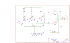
I'm also attaching an updated schematic. Basically I took some suggestions, moved the filament bias for the 6088s, and switched from using negative feedback to hold the PI to unity gain to just voltage-dividing the input. I found the negative feedback approach made PI clipping more abrupt, while just reducing the input made it act more like what was going on at the other rail in the 2nd gain stage.
After experimenting, I found that setting the negative sides of my 6088 filaments at ground did indeed allow for more clean headroom than setting them at 1.25v, despite the data sheet specifying a typical -1.25v bias for the grid. I don't understand why, but I wonder whether the data sheet characteristic values are for pentode operation, whereas I have them triode-strapped. Doesn't make any sense when I try to draw load lines, though. Even after this change, all 6088 stages still clip first at cutoff rather than saturation.
Anyway, here's a short video of what I've currently got: YouTube
I'm also attaching an updated schematic. Basically I took some suggestions, moved the filament bias for the 6088s, and switched from using negative feedback to hold the PI to unity gain to just voltage-dividing the input. I found the negative feedback approach made PI clipping more abrupt, while just reducing the input made it act more like what was going on at the other rail in the 2nd gain stage.
Attachments
Biasing too close to zero makes a low impedance at the grid. In the intended application (very minimal radios) this was bad for performance. "Low" may still be hundreds of K-ohms, which is often acceptable in audio. And we sure are not worried about melting the tube at low voltages with large plate resistor. So just do what works.
Anyway you *are* negative bias. You have small tube filaments on 0V and +1.25V. Grids at 0V. On-average, the filament cathode is 0.625 above ground; grid is -0.625V from average of filament. Yes, small positive grid drive causes some grid current at the low end of the filament. But everything in there is tiny, so the current is tiny.
Anyway you *are* negative bias. You have small tube filaments on 0V and +1.25V. Grids at 0V. On-average, the filament cathode is 0.625 above ground; grid is -0.625V from average of filament. Yes, small positive grid drive causes some grid current at the low end of the filament. But everything in there is tiny, so the current is tiny.
Last edited:
Tried switching the 2nd stage and PI to 5678s today (leaving a 6088 in the first stage because it already has plenty of gain to drive the 2nd stage into distortion). I still have some tuning and experimentation to do, but already this is a big improvement: lots more clean volume and punch, as well as more crunch when I crank up the first stage's gain.
The 5678 data sheet calls for a 0v grid bias, but these are also still clipping at cutoff and seem unable to reach saturation. I wonder if I should put a small positive bias on the grid — is that an okay thing to do?
I may also try bringing the plate voltage up to 60v since these can handle a little more than the 6088s.
There are some subminis that work well until +1v grid bias (The russian rod tubes). I'm not sure if it applies, in any case it won't drain current enough to burn. So you can give it a try.
You definetely should try running the 5678 at 60v. In my build I run them between 60v and 40v (first stage)
You definetely should try running the 5678 at 60v. In my build I run them between 60v and 40v (first stage)
Running the 5678s at 60v yields another nice little increase in volume.
Alas, bringing their plate resistors above 30k doesn't seem to do much of anything. Up to 25-30k or so increasing the plate resistor value increases gain. From about 30k to 150k I don't see or hear any change in the output whatsoever. Didn't try higher than that.
At the max clean volume I can get out of my second stage, the quiescent voltage on the plate is now about 35v and my sine wave input is swinging about 16v peak-to-peak, so I guess that's up to ~43v and down to ~27v. Boosting input volume beyond that point, the bottom of the waveform will drop much lower and looks clean, but it starts to square off at the top.
Could it be something to do with the fixed bias?
Have you tried using a battery at the filaments and referencing the cathode through a resistor, like normal cathode bias? I guess the battery will be floating according to the cathode bias.
Another thing would be to measure the plate current, to know how good the tube compares to the datasheet, or what is actually happening.
Okay, tried a bunch of experiments.
Powering the 5678 and 6088 filaments with a battery doesn't seem to change anything. Referencing through a resistor does reduce gain a little bit — I guess this is acting like normal cathode bias negative feedback. Doesn't affect the cutoff headroom issue.
Bringing the grid bias up 0.5-1v with a battery and voltage divider connected to the grid likewise doesn't seem to have much effect.
Finally, I measured the plate current of all the tubes. For preamp stages, I did this by inserting my multimeter in mA mode between the HT rail and the plate resistor. For the output stage, I inserted the multimeter between the transformer lead and the plate. Here are the results:
Stage 1 6088: 0.4mA to 0.9mA, as I turn the gain knob down, varying the plate resistor from 28.9k down to 3.9k. The datasheet indicates a typical plate current of 0.65mA (though probably for pentode operation), so this seems to be in the right range. Output looks clean at all settings.
Stage 2 5678: 0.5mA with the plate resistor at 30k. Increasing the plate resistor to 110k brings plate current down to 0.25mA, but has almost no effect on gain. Decreasing the plate resistor to 10k brings plate current up to 1.0mA, and cuts gain in half. The datasheet suggests a typical plate current between 0.8mA and 1.8mA, so this all seems pretty low, right? I wonder if reducing plate current below 0.8mA, I'm just asking for more gain than these things can provide. But, I don't understand why current is as low as 0.5mA with the plate resistor at only 30k.
Phase inverter 5678: looks exactly like stage 2.
Output 5672s: 1.2mA quiescent. Comes up to 2.2mA with a maximum clean volume signal. The datasheet says typical plate current is 3.25mA, so I guess this suggests I have quite a bit of headroom still in the output stage.
can you test a different 5678?
Im my amp I saw that the tung-sol tubes have more gain than some raytheon using the same plate resistor and bias. Not sure if it was just a bad raytheon or a very good tung-sol. I only had two tung-sol tubes and both had a larger voltage swing than all the 3 Raytheon I tested.
Lower current could mean a bad tube or we are missing something.
Just a dumb question, but you have noticed that the negative side of the filament of the 5678 is the opposite of the 5672? One of them has the negative pin at pin 5 and the other at pin 3. Not sure how much it could change, but you could check it.
Hm, all the 5678s I have are from the same RCA pack of 5. The two I've used seem similar, but I can try swapping another one in. Maybe I can get my hands on some more 5678s to see whether this batch is bad...
I had noticed the different pin out from the 5672 filaments. Just for kicks, I tried swapping the 5678s to the wrong way around just now, and they seem to work exactly the same either way.
I had noticed the different pin out from the 5672 filaments. Just for kicks, I tried swapping the 5678s to the wrong way around just now, and they seem to work exactly the same either way.
I tried a couple other 5678s from my pack of 5. Some have a touch more gain than others, but they all seem to start clipping at cutoff somewhere around a 16-20 volt peak to peak swing.
I've got Tung-Sol and Westinghouse 5678s on the way, so I should be able to compare some that aren't from the same batch in a few days here.
Thomas, do you know roughly what maximum voltage swing you're able get from a 5678 in your Mesa-inspired build? If it's a lot more, I may try building your design to see how it compares to what I'm doing.
At the 4th stage I got a peak at +15v and -19v on the negative side, so 34v peak to peak in triode mode, but my input is 16v peak to peak. The cathode is biased at -1.06v, with 46.9V at the b+ node.
All the other stages have lower peaks.
The 3rd stage produces 27v peak to peak when measuring with an oscilloscope at the plate. At the 2nd stage it is 28v, but very asymmetric, with a positive peak of 9v and a negative of -19v, more than twice .
Maybe that's indeed the limit of the tube.
All the other stages have lower peaks.
The 3rd stage produces 27v peak to peak when measuring with an oscilloscope at the plate. At the 2nd stage it is 28v, but very asymmetric, with a positive peak of 9v and a negative of -19v, more than twice .
Maybe that's indeed the limit of the tube.
> the limit of the tube
As a wild rule of thumb, a triode volt-amp stage "should" make a peak 20% of its supply voltage. For a 300V B+, 60V peak (120Vpp). This will be "undistorted", <5% THD.
You have 45V of B+? Then the RoT says 9V peak (18Vpp). You seem to be doing "very much better" (at unstated THD), so I think your result is reasonable, and about as good as it gets.
My B+ for the 5678s is now 60V. So, I guess I'd expect a peak of 12V or 24Vpp. I think this aligns better with the new numbers I'm about to mention than with what I was seeing before.
Anyway, I've had a minor breakthrough, as a result of a couple of happy accidents.
First, though: a Tung-Sol 5678 arrived and I tried swapping it in. It has a bit more gain (+1-2Vpp on the output) than the RCAs I was using, and also higher current with higher plate resistor values, so that the maximum gain is at around 100k instead of 30k. But, it is broadly similar in terms of how it acts in the circuit. It was still clipping at cutoff rather than saturation, just a touch louder than the RCAs. I was starting to think that's just the nature of these tubes.
But then I started tweaking some of the other values, measuring various things, just trying to understand things better. I read something about grid resistors that said 1.5k is a typical value in output stages, so I popped some 1k resistors in series with the the 220Ω I had there (on the grid of the 5672s, just after the troublesome 5678s).
But as it happens, I misread a resistor value as 1000Ω when it was actually 1000K. With that 1M resistor in place, suddenly I could swing the output of my 5678 30Vpp before obvious visible/audible clipping (was about 20Vpp before)! Messing around a bit, it seems things start to get better with about a 10k grid resistor, and beyond about 1M things don't improve much. The good news is that this lets me get a much louder clean output from the amp. On the other hand, I have almost no idea why! I'm guessing grid current is involved somehow.
The other happy accident: I had been using an LM317 linear regulator to provide a 45V B+ for my 6088 first stage. Well, I somehow fried the LM317 (while fiddling with adding a capacitor to try to reduce hum), and it started dumping its input 60V straight through to the 6088. Fortunately that's within spec! Anyway, turns out the LM317 was producing most of the hum, so good riddance. I'm now supplying ~40V to the 6088 from a simple 22k/(10k+22k) voltage divider instead. The lower noise floor helps a lot.
Last edited:
- Status
- This old topic is closed. If you want to reopen this topic, contact a moderator using the "Report Post" button.
- Home
- Live Sound
- Instruments and Amps
- Submini 6088 and 5672 PP amp, please critique