hi all,
I have been restoring a pp amp to run a guitar through gone through the ps and replaced the dogey bits, the input goes
----> ecc40 pre -----> passive tone switch then master volume------>
------>ef86 2nd pre ------> el41 pi and power tubes.
if the guitar run clean or boosted and bypass the ecc40 works very well strong loud output,
if the guitar is input to ecc40 i get thin but ok signal at low volume, when i try to go louder on the master the output volume actually gets quieter,
I'm not sure if the gain of the ecc40 is wrong for the guitar signal, or if it is another fault or if the wiring is wrong from the factory. i have drawn the ecc40 circuit and bypassed the tone stack/switch for now to eliminate that as a fault until i test that part of the circuit.
i could video a demo if needed or would help?
cheers
Attachments
![IMG_5395[1].jpg](/community/data/attachments/679/679341-123ba882b3704c49e2e5c6b513a770e3.jpg)
Last edited:
The input needs a grid to ground resistor.
The output NEEDS a blocking cap, or the next box will be VERY distressed. Perhaps the removed tone network did that function?
I won't watch a video but I would like to see the thing this is based on.
hi, yes it has series cap between volume and ef86, the tone network still needs resto work because of very old style dial selector switches have tarnished over time and gives intermittent faults and need to check leakage on caps in tone circuit had 28% v-loss, thought that might be quite high so took it out the loop for now to carry on testing.
cant find any guitar amp schematics online that use an ecc40 as a pre to compare. was going to put a 1meg to ground on input grid but thought problem is probably more than that. tube is fine,
the schematic is factory unless i put the 47nf's and 100nf back on the wrong tabs.
cant find any guitar amp schematics online that use an ecc40 as a pre to compare. was going to put a 1meg to ground on input grid but thought problem is probably more than that. tube is fine,
the schematic is factory unless i put the 47nf's and 100nf back on the wrong tabs.
![IMG_5396[2].jpg](/community/data/attachments/679/679552-989922467174410214acd3cb91ce006d.jpg)
![IMG_5398[1].jpg](/community/data/attachments/679/679566-8e3c6606c74150bbc89cbb8fdd15faa4.jpg)
![IMG_5397[1].jpg](/community/data/attachments/679/679589-cda855a3dbbb70e98bbc90735937a6f4.jpg)
![IMG_5399[1].jpg](/community/data/attachments/679/679606-f1473d67a2983588b457cc8e320cce34.jpg)
The cathode follower triode isn't properly biased.
Either insert a cathode bias resistor between cathode and 100k resistor and move the ground part of the grid leak there, or connect the grid directly (without grid leak) to the anode of the input triode.
The first triode is biased very cold with that 10k cathode resistor. You probably won't have a lot of voltage drop over the first anode resistor.
The cathode follower triode isn't properly biased.
Either insert a cathode bias resistor between cathode and 100k resistor and move the ground part of the grid leak there, or connect the grid directly (without grid leak) to the anode of the input triode.
The first triode is biased very cold with that 10k cathode resistor. You probably won't have a lot of voltage drop over the first anode resistor.
Hi i think you are right i think im getting cross over cancellation when i try to play loud. I'm cant quite visualize what adjustments you are describing,
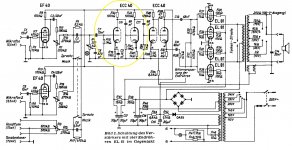
if you have time to draw me a sketch that would be great, or if you very busy I found a schem for a philips p.a. if you think i would be better to re-wire the ecc40 the same as in the yellow circle if the out put would be at a similar level to instrument or line level?
Attachments
The Cathode Follower gets bias OK.
Its grid voltage is direct coupled from the anode of the first triode via the 2 x 220K resistors.
The network which includes the 2 x 200K is called a "Twin T" Filter and it is a notch filter.
One "T" is formed by the 2 off 220K resistors and the 100nF to ground and the other "T" is formed by the 2 off 47nF capacitors with the 100K to ground.
10K seems way too high for the cathode bias resistor on the first triode. The data sheet suggests it should be 2K2. Thats sets the first triode idle current and hence the anode voltage . That anode voltage is what is seen at the grid of the cathode follower so it effectively sets the idle current for the cathode follower too.
Cheers,
Ian
hi, just done some research,
Notch Filter sharply attenuates frequency-specific noise like mains hum or electrical whistle with minimal damage to the remaining audio, by cutting a "notch" out of the frequency
might have been added there to remove unwanted noise from a tape or pu motor
Notch Filter sharply attenuates frequency-specific noise like mains hum or electrical whistle with minimal damage to the remaining audio, by cutting a "notch" out of the frequency
might have been added there to remove unwanted noise from a tape or pu motor
What does that mean? Is there a EL41 as phase inverter, followed by two EL41 finals? Or is it a self balancing final stage with just two EL41's? Or did you just omit another tube that is the PI?el41 pi and power tubes.
Best regards!
hi, the empty chassis socket in photo is plug for speaker wiring no tube goes there, the output transformer is located in speaker cabinet enclosure from factory, so plug wiring for extra wires from socket is for speaker selector switchWhat does that mean? Is there a EL41 as phase inverter, followed by two EL41 finals? Or is it a self balancing final stage with just two EL41's? Or did you just omit another tube that is the PI?
Best regards!
sorry of course you must be right a single el41 cant be a pi on its own i will have a better look at the output stageWhat does that mean? Is there a EL41 as phase inverter, followed by two EL41 finals? Or is it a self balancing final stage with just two EL41's? Or did you just omit another tube that is the PI?
Best regards!
.
10K seems way too high for the cathode bias resistor on the first triode. The data sheet suggests it should be 2K2. Thats sets the first triode idle current and hence the anode voltage . That anode voltage is what is seen at the grid of the cathode follower so it effectively sets the idle current for the cathode follower too.
Hi, i havent made any bias adjustments yet because i thought best to take some readings, just worried about the 100k bias on pin 4 as well, wondering if i should change that to about 2k2 at the same time.
thinking cathode 137v pin 4 to the volume vr and ef86 is pretty high or maybe the by passed tone circuit is ment to drop the voltage more before the ef86
-readings for ecc40-
anode pin 5 .....132v
input grid pin 6 .....0v
cathode pin 7......... 43v
anode pin 2 ......... 182v
grid pin 3.........128v
cathode pin 4.......137v
Attachments
![IMG_5395[1].jpg](/community/data/attachments/689/689305-123ba882b3704c49e2e5c6b513a770e3.jpg)
hi, i'm wondering if the tone switches in the photos are not tarnished, or if they maybe burnt from 137v going through them over time, and if the volume pot is maybe half ruined too or if that kind of voltage is normal for those components?
I always thought signal levels were quite low voltages until you got near the output tubes but maybe tube amps are different.
I always thought signal levels were quite low voltages until you got near the output tubes but maybe tube amps are different.
Hi, thank you. yes you were right, i read meter wrong. took the readings again wrote them on the schematic. Do you think this circuit as it is from factory can operate correctly or do think there is maybe a fault or in correct parts installed?> cathode pin 7......... 43v
We expect more like 9V, as seen G-K on the other half.
Bad reading? Bad cathode resistor? Bad joint?
if it seems normal i will look back at tone circuit if it is there to create a v-drop to bring the pin 4 voltage down
Attachments
![IMG_5437[1].jpg](/community/data/attachments/690/690606-b6dc90e67717a0a9b34d192ef0d23348.jpg)
i have reconnected the tone circuit and now have a reading of 2v at the volume pot instead of a crazy 130 something volts.
I will trace the tone circuit because i think there must just be a resistor to ground to adjust or a leaking cap letting to much signal ground that is causing the volume loss. the signal quality seems fine so i think maybe the ecc40 section is ok how they have built it
I will trace the tone circuit because i think there must just be a resistor to ground to adjust or a leaking cap letting to much signal ground that is causing the volume loss. the signal quality seems fine so i think maybe the ecc40 section is ok how they have built it
Last edited:
have mapped out the tone circuit and what i mistaken for cross over distortion was too stronger signal being sent the gain next stage.
with the tone circuit reconnected the signal voltage was brought down too quiet again, which strangely was a similar symptom of too much signal to the next stage.
the tone circuit has been adjusted to let less signal to ground. the amp works fine so am not sure that the ecc40 stage was biased incorrectly.
will try and find an tube online calculator that work out what range it is operating in, then try some bias adjustment from there.
am thinking alot of guitar amps dont use Negative Feedback so am wondering about self bias output stages and if this type output design has the same effect on the signal trying to drive the output stage as the NF does?
https://www.diyaudio.com/forums/ins...e-tone-circuit-gain-increase.html#post5761761
- Status
- This old topic is closed. If you want to reopen this topic, contact a moderator using the "Report Post" button.
- Home
- Live Sound
- Instruments and Amps
- ecc40 circuit adjusting posible fault