You 'have your work cut out for you' here at diyaudio where the majority of recommendations for hookup wire seem to involve Teflon!
It's good stuff.

But very few people seem to be aware of "Teflon flu", which I first ran into via frypan abuse (where it's easy to get above 450-650°F).
I understand the hotter the temperature, the more nasty the out-gasses.
Like most people sick of scrubbing out frying pans, my mother too fell for the promise of the nonstick, Teflon-coated ones when they first became available...."Teflon flu"...frypan abuse...
We didn't know about the health hazards of hot Teflon for quite a few years after that. Dupont scientists probably did, but they weren't about to do something that might kill one of their bigger cash cows ( Teflon’s Toxic Legacy: DuPont Knew for Decades It Was Contaminating Water Supplies - EcoWatch .)
-Gnobuddy
Oh, the agony of that wait!Just waiting on the delivery guy to show up.
")
But you'll have lots of enjoyable new toys to look at and play with soon!
-Gnobuddy
My shipment showed up RIGHT before I had to leave for work. So I got to unpack everything after a tedious 8 hour shift. Made a bit of progress. Going point with a couple of "lug strips" is proving to be a bit of a challenge but I believe my layout will work. I managed to get most of the power supply in place. Probably have to call it a night. Don't want to make any errors due to fatigue. I took a gamble on a Duratool 4004 for soldering station so far I am quite pleased with the result. Heats up quickly, digital readout and a knob for temp, and the price was right ($71.26CAD down from approx $225CAD regular price.)
Going point with a couple of "lug strips" is proving to be a bit of a challenge but I believe my layout will work. I managed to get most of the power supply in place. Probably have to call it a night. Don't want to make any errors due to fatigue.
I find that 'sleeping on it' sometimes helps me to think of alternative ways of wiring components together.
My brain tends to think that the schematic is a layout diagram, which it isn't. Often, junctions can be 'moved' to a more convenient place.
Re-drawing the schematic on paper in different ways is a good exercise.
And, yes, working when you are tired or sleepy is a bad idea!
Using a highlighter on the schematic when double-checking wiring can help to avoid mistakes.
I sometimes do this on graph-paper, so I can put down reasonably accurate footprints of things like integrated circuits or tube sockets. It may take a few iterations to get a layout I like.Re-drawing the schematic on paper in different ways is a good exercise.
I do tend to make layouts that are somewhat optimized for space, but which are intentionally somewhat close to the schematic. This is something I learned to do with solid-state circuitry, which is where I started as a young boy. And it's a very different approach than the sort of layouts found in vintage valve electronics.
For example, I tend to use a horizontal PCB trace or bus wire along the bottom edge for ground, and one along the top edge for the positive power rail. Signal flow (audio) is always from left to right. These are the same conventions widely used when drawing schematics.
For me, this makes wiring, modifying, and fault-finding much easier. I can think my way through the layout, just as I can with a schematic. It also makes it possible for me to start wiring a new project just by looking at the schematic, without having to follow a pre-designed layout.
My layouts never look anything like, say, the guts of a classic Fender amp. Leo was an accountant above all else, and I expect he optimized his layouts for entirely different parameters than I do: cost of the board, number of eyelets / turrets used, length of wire used, amount of solder necessary, stuff like that. Very relevant for mass production, but low priority for one-off DIY projects like the stuff I build for myself.
Good tip re using a highlighter to check off each wire as it's done! I recall a few diyAudio threads where a lot of time was spent fault-finding a newly built circuit, and the problem turned out to be a wire that had been omitted by accident.
-Gnobuddy
Major progress tonight! I just need to wire up the output transformer to a speaker, add one resistor to the negative feedback loop, add a 1/4 inch jack for my guitar, fuse socket, and power cord. Then after double and triple checking my connections I'll try firing it up possibly tomorrow evening. Here is a shot of my progress so far. Please be gentle if my technique isn't quite up to standards.
Attachments
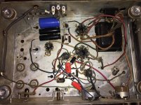
Also just a question that I'm pretty sure I already know the answer to. If an output transformer has only one set of secondary leads. Does is matter which side is ground and which side is hot? Anyhow probably something I'll try looking up later on. Anyhow bedtime! More soldering to do after work tomorrow and hopefully be doing some tests by the evening.
Thanks guys! Almost there
Thanks guys! Almost there
Here is a shot of my progress so far. Please be gentle if my technique isn't quite up to standards.
Pretty scary!
One of the main 'rules' of point-to-point wiring is that all connections should be made at a lug - a secure mechanical point. The rule is sometimes broken, but it's a good guideline to follow.
If you look at enough old gear first-hand and examples on the internet, you'll get the idea.
Your wiring is more 'breadboard style' or 'dead bug style' in places. OK to see if the thing will work, but probably not ready for safe long term use, IMO.
You have already seen why capacitors are available in axial and radial lead styles - there's a good use for both styles in many projects.
Attachments
Last edited:
If I am reading your layout correctly, there are some areas that are, as VictoriaGuy said, scary: and I mean literally scary, as they could pose you considerable danger.Pretty scary!
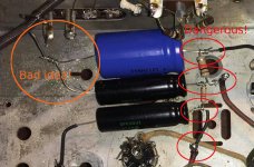
Look at the positive leads from your big electrolytic filter caps (red ellipses in the attached image) - they seem to be hovering unsupported a fraction of an inch above your bare metal chassis. Those wires are at something like +300 to +350 volts, and the metal chassis is connected directly to your guitar strings via the guitar cable.
Guess what happens if those capacitor leads bump against the bare metal chassis while the guitar is in your hands?
That's right, your hands come into contact with 300 - 350 volts. That much electricity will often cause your muscles to contract uncontrollably, so you might find your hands clamped to the guitar while it shocks the bejeezus out of you. You could wind up injured or dead.

You want to make sure that no bare wires or wire ends can come into contact with anything they shouldn't. The orange circle shows an example of this - the negative leads from those big filter caps are likely to intermittently touch the chassis. In principle this is not dangerous, but it will certainly make nasty noises through the speaker - scratching noises, thumping noises, pops, bursts of hum, et cetera.
This is why every joint should be anchored securely to a solder tag, and bare wires should be covered by insulating heat-shrink tubing.
Based on what I've seen, I'm seriously concerned about your safety. These are potentially lethal mistakes, and while I've spotted a few, I don't know how many more might be lurking in your build.
It's absolutely vital that your chassis is properly wired to AC ground (not neutral, not live, only ground). That might save you from electrocution due to other mistakes (such as the filter cap wiring I highlighted.) But if this mains AC wiring is done wrong, that can be lethal as well.
Is there any chance you can get someone with some experience with valve circuitry to look over your build BEFORE you apply power? Perhaps someone at BC Robotics, or a local guitar amp tech, if there is one?
Please be safe - your life and health are far more important than any guitar amp.
-Gnobuddy
Attachments
Thank you. I will take my time and make adjustments to address these issues. The positive leads have a lot more clearance from the chassis than it looks in this picture (approx 1 centimeter, there isn't a lot of depth perception in the shot) but I will still look at minimizing any bare wire exposed. In any case I will take a break from my project to reconsider a few points. I'm not in any rush to get it done.
Firstly, thank you very much for slowing down and taking time to consider. It's the right thing to do, and a very wise decision on your part.The positive leads have a lot more clearance from the chassis than it looks in this picture (approx 1 centimeter...
I am not a certified electrician, and therefore, I am not an authoritative source of electrical safety advice. Like you, I'm an amateur who wants to build valve equipment and stay alive and well. I've tried to learn as much as I could about safety, and will mention a few points I'm aware of.
Soft unsupported flexible wire leads a mere centimetre from being an electrocution hazard are nowhere near an acceptable risk. If those same leads are covered with heat-shrink tubing, with only a few millimetres of bare wire exposed, and those few millimetres are securely soldered to a securely mounted rigid solder tag, then at least you meet the safety standards of 1940 or so - though I'm pretty sure this will not come close to meeting current electrical standards.
Nowadays, one of many required tests for electronics equipment is that it be tested with a "standard test finger" ( What is a "standard test finger" tester? - EE Publishers ). The finger should not be able to touch any dangerous voltages.
This usually comes down to having a safe insulated or grounded housing around the dangerous bits, with no openings big enough to admit a finger, and of sufficient size that a finger couldn't reach through any cooling holes far enough to touch anything dangerous.
So if all the dangerous bits in your chassis are securely mounted, with sufficient "creepage and clearance distance" ( https://uploads-ssl.webflow.com/596...tanding_Creepage_&_Clearance_Measurements.pdf ), and the chassis is grounded to the AC ground, and there is a cover plate preventing access to dangerous bits, and there are no holes big enough to admit fingertips, you at least have some minimum amount of safety.
Other safety-related stuff to consider: how is the AC mains wiring going to be connected to the transformer? It must be switched and fused for safety, and an external yank on the wire must not be able to pull the dangerous live wire loose inside the chassis, where it can wave about, touch the wrong thing, and electrocute or shock the guitarist.
I use an IEC cord from wall to chassis (the kind of power cord you see on the back of your desktop computer, for instance), and a matching IEC inlet on the chassis. There are IEC inlets that include an on/off switch and a fuse housing (fuse sold separately!) that simplify wiring, and that is what I usually use.
Hopefully others who do have electrical safety certifications in BC or elsewhere will chime in and offer their good advice.
-Gnobuddy
The fuse and switch should both be in the 'hot' side of the input AC wiring IMO.
This is my plan for the AC wiring. Hot wire of AC going into fuse then into one side of switch. I do like the idea of the removable style AC plug. The IEC style plug seems a good idea.
Last edited:
Thank you. I will take my time and make adjustments to address these issues.
Good!

I sent you a few lug strips in the box with the transformer - mainly to show you what you should be ordering from a supplier...you'll probably need more.
And, you may well find that you need more resistors/caps if some cannot be re-used because the leads have been trimmed.
You can extend leads from transformers by soldering extra wire (preferably of the same colour) and covering the joint with heat shrink. However, it's better to put a lug strip in a good spot, solder the transformer wire to the lug, along with the 'extension' wire.
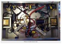
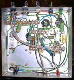
You said that you had found some other old tube gear? See how those were wired - it pays to study them.
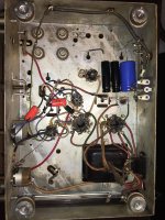
Like Gnobuddy, I am concerned that your amplifier is not safe.I have the unit safely up and running.
Even if you have good 'luck' with it, your amplifier could end up with a different user - I'm sure you would never forgive myself if some kid ended up dead because something came loose in the amp.
If you post some details (pictures) of the changes you made to get it running safely, it would help us to be less anxious!
It's excellent that you have gotten your first project working, but for most of us, good craftsmanship is satisfying. I think we have all re-built projects to make them better, and safer. You are not alone in this.
Just to add to a couple of things earlier in this thread:
Wiring Colour codes are also covered in a thread I started here:
Amp Wiring Color Code
Modern Teflon (PTFE) insulated wiring is used because of its high temperature stability and because it does NOT out gas at higher temperatures.
In the day job we build lasers and all wiring inside the laser is specified as PTFE insulated as we don't want any out gas material getting on the optics.(we've all seen in the movies what happens when the laser optics get dirty!!! - usually its not that dramatic but damage does occur, requiring an expensive repair).
The lasers are used in airborne survey gear and all of the in house build companion electronics are also specified to be wired with PTFE insulated wire. PTFE insulated wire is not absolutely required for the companion electronics BUT PVC insulated wire is NOT to be used as it DOES emit toxic fumes at high temperatures, which is exactly what you do not want in a closed environment like a presurised aircraft cabin.
Using PTFE insulated wiring makes the airworthiness approval process easier as NO PVC it is one of the many things they check for.
I'm wondering if earlier poster confused PTFE and PVC and got them backward with respect to which can be hazardous at higher temperatures and which is not.
Use PTFE insulated wire with confidence.
Cheers,
Ian
P.S. Day job is Senior Electronic Engineer - Laser Airborne Depth Sounder
Last edited:
- Status
- This old topic is closed. If you want to reopen this topic, contact a moderator using the "Report Post" button.
- Home
- Live Sound
- Instruments and Amps
- First Tube Amp Project