Hello everyone out there in diyaudio land! I have come across an old Stromberg Carlson Radio (Model 1502) The bad: It was completely filthy, the tubes were all fried and the output transformer was bad. The good: Power Transformer appears to work and it looks quite nice, the speaker is still in good shape albeit 5.5" and 4Ohms the tube sockets appear to be usable, and the chassis looks like a solid foundation. What I am interested in doing is converting this bread box sized Radio into a slightly modified Fender 5F1 champ combo/head. After a few drafts I have come up with a schematic that I think will work. Would anyone here be able to provide me some feedback. I don't know anyone locally that can check my work.
Attachments
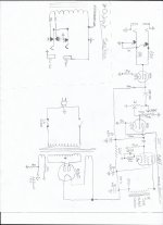
Looking at the original 5F1 schematic, here's what I can see.
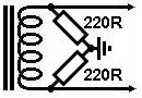
- The artificial center tap is incorrect, both 100 ohm resistors should be grounded while keeping the tube pin ungrounded.
- The negative feedback shouldn't be on the grounded side.
However, please wait to get more advice since I'm no expert.
- The artificial center tap is incorrect, both 100 ohm resistors should be grounded while keeping the tube pin ungrounded.
- The negative feedback shouldn't be on the grounded side.
However, please wait to get more advice since I'm no expert.
Add a capacitor to the first cathode. Tou might want to look at these guys if you are in the US.
Antique Electronic Supply
Antique Electronic Supply
The radio has one side of the heater circuit grounded for simplicity and RF stability. The low audio gain and teeny speaker make the hum acceptable. Early guitar amps were this way.
Pretty soon g-amps switched to wiring both sides of the heaters (not using chassis return), which leads to the plan hex69 has posted (which your drawing attempts but not-right).
Pretty soon g-amps switched to wiring both sides of the heaters (not using chassis return), which leads to the plan hex69 has posted (which your drawing attempts but not-right).
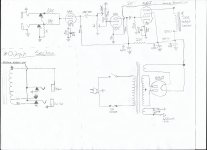
Thanks for the info guys. So it should look more like this?
If you are planning to re-use the radio chassis and tube sockets, my advice would be to leave the heater wiring 'as-is', since one heater tab on each tube socket is probably soldered to the chassis.The radio has one side of the heater circuit grounded for simplicity and RF stability. The low audio gain and teeny speaker make the hum acceptable. Early guitar amps were this way.
Pretty soon g-amps switched to wiring both sides of the heaters (not using chassis return), which leads to the plan hex69 has posted (which your drawing attempts but not-right).
It is a PITA to 'un-ground' those tabs, and a lot of hobbyists don't have a big mass 'old school' soldering iron to do the job.
So just delete those 100 ohm resistors on the heater circuit schematic IMO.
If you plan to use the transformers in a new build, on a new chassis, you can arrange the heaters differently.
Thanks for the info guys. So it should look more like this? My brain has gone a bit mushy over the past few days trying to hash out all of the details.
The fuse and switch should both be in the 'hot' side of the input AC wiring IMO.
Would anyone here be able to provide me some feedback. I don't know anyone locally that can check my work.
If you add your location to your Profile here, it will show under your user name.
This is useful when people are advising on AC wiring, voltages, etc....which differ from country to country....
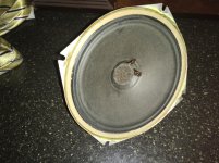
I have come across an old Stromberg Carlson Radio (Model 1502) The bad: It was completely filthy, the tubes were all fried and the output transformer was bad. The good: Power Transformer appears to work and it looks quite nice, the speaker is still in good shape albeit 5.5" and 4Ohms the tube sockets appear to be usable, and the chassis looks like a solid foundation.
If you were able to test the tubes and transformers, you must already have quite a lot of skill and experience.
What voltage (AC) does the power transformer put out on the HV winding?
You chose the preamp tubes because you have 7-pin sockets available?
BTW, you had bad luck if all the tubes and the output transformer were fried- yesterday I got (free) a 1963 Grundig tube stereo console which works and had all original tubes except for one replacement. Tube don't 'wear out' very fast in most cases!
The chassis has three mini 7 pin tube sockets along with two octal sockets. I'll have to check my notes for the HV winding if my memory serves me correctly I was getting about 370VAC from centre tap to each side. It seemed a bit high but I took the readings with "no load" if I'm using the term correctly. BTW I am in Nanaimo. Not very far from Victoria indeed.
Adding a tone control moves you to a tweed Princeton circuit, so you can find lots of those online. Here's a variant: GAA's Tweed Princeton Clone
I wouldn't bother with the two inputs that a lot of those early amps have.
You could wire up the power supply and put a resistor across the B+ output to draw 30mA or so to give you an idea of the voltages you can expect. Do you have a copy of PSUD from Duncan Amps? It's useful.
BTW, it wounds like you will be looking for tubes. John Albion at Pacific TV (Victoria) is trustworthy. I've also gotten good service from tubestore in Hamilton, ON. For other components, Digikey and Mouser both have excellent quick and reasonable shipping to Canada. I've bought transformers and chokes from Allied and MusicalPowerSupplies, but shipping iron is expensive. Hammond iron via Digikey/Mouser might be cheaper in the long run.. Avoid Newark- they split my $50 resistor order into three parts and charged $30 shipping for each part. Live and learn.
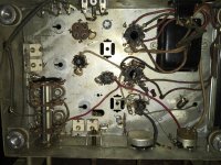
The rectifier tube glass is no longer vacuum sealed. Other tubes have very toasty looking glass bottles almost as if they were on the verge of melting down. By the way the power supply hi voltage read 378VAC from each side to tap. Thanks for all the advice. I may test out the PSU further with a resistor across the B+ to get a better idea of voltages. I’ll have a look at the PSUD from Duncan amps. I appreciate any good material to help me understand things better.
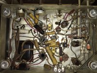
Before and after some "tidying up"
You've made a good start!
It's not easy to 'undo' older solder joints without breaking the lugs on the tube sockets. For me it's usually the 'last one' on the socket that snaps....

A solder sucker and/or a lot of solder wick helps.
If you have to buy new tubes anyway, you could think about just step-drilling one of the holes for a 7-pin socket and installing a 9-pin (12AX7) new socket.
Pacific TV should have some goodies for you. Reasonable prices but CND shipping sucks.
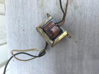
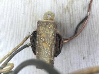
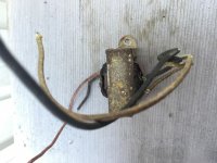
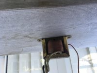
Have a picture of the OT, how do you know it is fried? Be handy if it wasn't. What was the tube types in the radio? Could help in determining your PT capabilities.
Tube compliment is as follows: 6BE6 (heater current 300mA, Plate current 2.9mA) 6BA6 (Htr current 300mA, Plate current 11mA) 6AV6 (Htr current 300mA, Plate current .5mA @100V) 6V6 (Htr current 450mA Plate current 35mA @315V) So approx 2A on the 5v 1.35A on the 6.3v line and 50mA on the hi volt. I’ll have to review my calculations. The 6AV6 plate voltage is operational specs list a fairly weak plate voltage of 65V. 6BA6 and 6BE6 @ 230V and 6V6 @ 330V. These “operational specs” are listed voltages of each plate taken from the service manual for this unit. I’ll upload some shots of the OT shortly.
Thanks
John
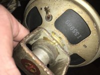
In regards to knowing the OT is fried. To be honest I’m no 100% certain. Based on a few things I read there are a few ways to test them. I tried measuring for resistance in the coils and the readings were somewhere in the hundreds of MegaOhms. Anything else I should be considering?
6AV6 plate voltage is operational specs list a fairly weak plate voltage of 65V. 6BA6 and 6BE6 @ 230V and 6V6 @ 330V. These “operational specs” are listed voltages of each plate taken from the service manual
65V on First Audio is perfectly normal.
230V on Conv and IF is less common, they were often run from 110V raw DC dropped near 90V. They work fine that way. The First Audio may be a big drop from 230V or a small drop on a 100V source, but it hardly matters since the 6V6 only needs like a dozen Volts of drive.
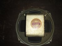
That OT *may* be good. Sometimes the great globs of varnish or tar were there from the factory dip. Often they are not pretty-- radio buyers never looked inside.
The First Audio and 6V6 was already a fine audio amplifier. Maybe did not need a complete strip-job there. A radio will be a fine guitar amp if you add one more stage. The 6BE6 IF tube, triode-strapped, will work. (Yeah, it's remote cutoff but this is for guitar....)
In regards to knowing the OT is fried...... I tried measuring for resistance in the coils and the readings were somewhere in the hundreds of MegaOhms.
A 'good' small OT will have at most a few ohms resistance on the secondary, and hundreds or a few K ohms on the primary, if a couple I just measured here are typical.
Next question would be what caused the OT damage, I suppose.
A radio will be a fine guitar amp if you add one more stage.
Let's not get too carried away!
- Status
- This old topic is closed. If you want to reopen this topic, contact a moderator using the "Report Post" button.
- Home
- Live Sound
- Instruments and Amps
- First Tube Amp Project