> OT .... resistance in the coils and the readings were somewhere in the hundreds of MegaOhms.
Short the winding you are not measuring.
Some DMM ohmmeters get confused by the high inductance of an OT, and give impossibly high readings.
Also it is unlikely that both windings went open.
Short the winding you are not measuring.
Some DMM ohmmeters get confused by the high inductance of an OT, and give impossibly high readings.
Also it is unlikely that both windings went open.
There is no continuity between the two leads coming out of the primary. Would that establish anything? There should be continuity on both sides. But it's only showing on the secondary.
Also with a makeshift audio signal generator I hit the Primary with 32.45 VAC and the secondary was reading .050VAC. I'm not sure if any of this data is pertinent without more sophisticated tools the amperage of the signal would have been fairly weak 35mA approx
From what I can gather. Putting variable amounts of low current AC voltages ranging from 1VAC to 32.45VAC the overall impedance ratio from Primary to Secondary is coming up anywhere from 2000-2600(Primary):4 ohms (Secondary). Doesn't seem quite correct. But once again there could be something I am missing. Although at 8 ohms that would put it in the 4000-5200:8 ballpark. But the speaker is definitely rated at 4ohms I need to rest and do more homework obviously. Thanks again everyone for your support!
I think the best secondary voltage for the 5F1 would be from 240-0-240 to 300-0-300 VAC, your transformer (378-0-378) will lead you in the 450VDC ballpark on the B+ (loaded), maybe a JJ 6V6 would do but seems high to me. Once you have 430V~ VDC on the plate, trying to get the idle dissipation down to 12-14W results in so little current that it won't be anywhere close to center-biased and may not sound good.By the way the power supply hi voltage read 378VAC from each side to tap.
To check OTs I'm using a little 7.3 VAC transformer, then by using the voltage obtained at the secondary I do the following maths:
Example:
7.3 VAC primary
0.205 VAC secondary
7.3 / 0.205 = 35.6
35.6 ² = 1267.4
1267.4 * 4 (ohm) = 5069.6
So I know by using this output transformer with a 4 ohm speaker would reflect about 5000 ohm at primary.
Hope this helps.
I'm trying to understand the multitap wiring on your schematic, not so easy to ground secondary tap by using 2 jacks, the connection I circled in blue will short your 4 ohm tap while the speaker conected to the lower jack (ext) so it's not gonna work.
Edit: Okay my bad, please ignore what I said.. by using both jack with two 8 ohm speakers paralleled, your wiring seems correct.

Here's the wiring I ended with, maybe it could be useful.

It uses only one speaker jack then its easier to ground taps, a DPDT switch (ON/ON) and the correct NF resistor for each tap. Not yet tested..
Hope this helps.
Edit: Okay my bad, please ignore what I said.. by using both jack with two 8 ohm speakers paralleled, your wiring seems correct.
Here's the wiring I ended with, maybe it could be useful.
It uses only one speaker jack then its easier to ground taps, a DPDT switch (ON/ON) and the correct NF resistor for each tap. Not yet tested..
Hope this helps.
Last edited:
I asked about the speaker being a field coil, it isn't. The manufacturer had the amplifier running with a 5Y3 and a 6V6, I expect the voltages to settle down to a reasonable value. After all, it was not Fender designing the amplifier trying to get the most out of it.Hope this helps.
I know it's feasible, seems that lot of people are going over the specs.. didn't want to argue with you on this for sure, it was just my 2 cents, holding on the little knowledges I have and trying to learn at the same time.
The OP said that he wanted to convert his radio into a 'slightly modified' Fender 5F1 champ combo/head.
378 VAC seems to me far over the specs compared with 50's and 60's Champ, although not optimal to get the 'typical tone'.
That's why I said 'the best'.
Because the manufacturer had the radio running with a 5Y3 and a 6V6 doesn't mean to me that it would be 'the best' transformer to built a champ then get that typical tone, or maybe I misunderstood something about plate voltage VS tone, please if I'm getting wrong don't hesitate to correct me!
Rarely used, I think any 6V6 would handle that voltage for some time, JJ's 6V6 are known to handle high voltages better, maybe there are others.. tubes also handle redplating for some time prior to fail.. but what about the OT? What would be a reasonable (maximum) value for 6V6GT plate voltage?
Transformers.. and speaker(s) also play big part in the overall tone, so it's clear that it will be a Champ 'Alike'")
The OP said that he wanted to convert his radio into a 'slightly modified' Fender 5F1 champ combo/head.
378 VAC seems to me far over the specs compared with 50's and 60's Champ, although not optimal to get the 'typical tone'.
That's why I said 'the best'.
Because the manufacturer had the radio running with a 5Y3 and a 6V6 doesn't mean to me that it would be 'the best' transformer to built a champ then get that typical tone, or maybe I misunderstood something about plate voltage VS tone, please if I'm getting wrong don't hesitate to correct me!
Rarely used, I think any 6V6 would handle that voltage for some time, JJ's 6V6 are known to handle high voltages better, maybe there are others.. tubes also handle redplating for some time prior to fail.. but what about the OT? What would be a reasonable (maximum) value for 6V6GT plate voltage?
Transformers.. and speaker(s) also play big part in the overall tone, so it's clear that it will be a Champ 'Alike'
Lot of Champ-a-likes out there. I have a 6K6 version that runs both Tweed and Blackface controls. It is all good as long as it makes noise. As far as the power transformer is concerned seeing what it will do with a load on it is the real test. Might have a high secondary impedance.
As far as the power transformer is concerned seeing what it will do with a load on it is the real test. Might have a high secondary impedance.
Does it mean the loaded voltage will be lower?
You are experienced, I learned (and still learn) a lot by reading from your posts, we beginners are trying to understand until experimentation, which is easier to do with enough knowledges,
At worst, OP could drop the B+ voltage by using resistor(s), diodes, choke, or another easy way is to setup a buck transformer and reduce the primary voltage at about 114-117 VAC, which is closer to the voltage a lot of old tube transformers were designed for.. I built mine in a separate box so I can use it with all my old tube amp, capacitors are living a better life.
So I did some further testing. (Again with no load) to see what kind of B+ voltages I would get out of a rectifier hooked up to the PSU. Comes out at approx 400vDC. I might have to put something in terms of resistance in from of the 6V6 Plate and OT if the voltages remain high when given a real "load". My apologies if my terminologies are not correct. Still learning.
Seems perfect and that's far better of what I thought, you're in business! (always have your eyes wide open while reading at experienced people) that's what I learned todaySo I did some further testing. (Again with no load) to see what kind of B+ voltages.....Comes out at approx 400vDC.
By taking the primary/secondary voltages and DC resistance then by using PSU Designer II (simple) you can have a good idea of the DC loaded voltages you will get at all stages.
Last edited:
The transformer has a resistance and whatever current you have flowing has to flow through it. Think of the transformer as a voltage source with a resistor in series (resistance of the winding). So what current you have flowing flows through the resistor and with ohm's Law you can figure out the voltage developed across the resistance. This voltage is subtracted from the open circuit voltage. You get a voltage drop from the tube rectifier (or SS if that is that you are using) which also drops the voltage. Duncan PSU will do some simulations for you, lot of fun for days checking out different combinations.
Seems perfect and that's far better of what I thought, you're in business! (always have your eyes wide open while reading at experienced people) that's what I learned today
By taking the primary/secondary voltages and DC resistance then by using PSU Designer II (simple) you can have a good idea of the DC loaded voltages you will get at all stages.
I had the chance to play around with PSUD II not sure if I'm putting in the correct resistances on the capacitors and the transformer?? Not able to find much a tutorial for the software.
Attachments
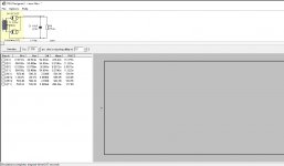
I had the chance to play around with PSUD II not sure if I'm putting in the correct resistances on the capacitors and the transformer?? Not able to find much a tutorial for the software.
If you right-click on a section or component you will get the 'Edit' window. The 'Help' button in that window will give specific hints, which might help.
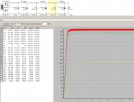
To see the output, you need to check some of the boxes at the left.
Attachments
@Printer2
Well, I was wondering about the DC resistance needed in PSU Designer but now it all makes sense to me.. crystal clear in my head, thank you 'very much' for explaining!
Well, I was wondering about the DC resistance needed in PSU Designer but now it all makes sense to me.. crystal clear in my head, thank you 'very much' for explaining!
The resistor must be replaced with a current load on each stages you have.. you can see in VictoriaGuy's example the guesstimate load he puts for the 6V6 (35ma) and both 6AV6 (5ma).I had the chance to play around with PSUD II not sure if I'm putting in the correct resistances on the capacitors and the transformer?? Not able to find much a tutorial for the software.
> play around with PSUD
Don't burn your brain. This rig DID work for Stromberg, with 6V6 and a rectifier bottle. Fender Champ WAS good radio parts, tuner omitted preamp added. All this stuff used essentially the same parts, will work the same.
Anyway: you expect 400V no-load to sag 10%-20%, making 360V-320V. Allowing for cathode bias and preferably a little more B+ filtering, this is right on target for the nominal 315V-350V rating on classic 6V6. 99% of 6V6 will stand far higher voltage, and Fender pushed those limits in some models. But here you are NOT doing showroom comparisons between Fender Gibson Ampeg and Kay (so you like it to seem "more"), you are aiming for a garage/small-tavern amplifier and will be happy with what you get.
Attachments
Last edited:
Thanks! Some sage advice. Especially about burning my brain. I'll begin focusing a bit more on my layout and hopefully have some progress to report. (Or more likely questions.) On a slightly different tangent, I'm considering using a multi section capacitor. Does anyone have anything they can weigh in on about that vs x3 Sprague Atoms?
> play around with PSUD
Don't burn your brain. This rig DID work for Stromberg, with 6V6 and a rectifier bottle. Fender Champ WAS good radio parts, tuner omitted preamp added. All this stuff used essentially the same parts, will work the same.
Whatever fits with your existing chassis layout will be OK IMO, though if you are using a 'can' cap above the chassis, try to keep it away from the hot tubes.On a slightly different tangent, I'm considering using a multi section capacitor. Does anyone have anything they can weigh in on about that vs x3 Sprague Atoms?
Single (axial leaded) caps will probably be cheaper, though you may need to add a lug strip to get connection points. The lugs on 'can' caps provided those connection points in most gear that used them.
For power supply filter caps, IMO as long as the specs (voltage, temp rating- I prefer 105C usually-) are suitable, any standard quality cap from Digikey/Mouser will do the job.
The "can" cap would fit the chassis nicely as this was the original layout.It also might make it a bit tidier under the hood. As for the spacing the cap would sit about 1.5" from the rectifier tube.
Unless there is some special trick to measuring the secondary impedance I measured it at 610 ohms. Which definitely settles down the B+ voltage a bit when I change to that value in PSUD II.As far as the power transformer is concerned seeing what it will do with a load on it is the real test. Might have a high secondary impedance.
- Status
- This old topic is closed. If you want to reopen this topic, contact a moderator using the "Report Post" button.
- Home
- Live Sound
- Instruments and Amps
- First Tube Amp Project