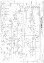
I had one of these arrive for servicing, no schematics or other data on the internet so this meant reverse engineering and this is a record of how the servicing evolved. This is work in progress as only the power and output board has been done but for those seeking this 'hens teeth' information, well it is a start.
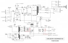
http://www.g4cnh.com/public/Carlsboro_Sidewinder_60_Watt_Amplifier.pdf
http://www.g4cnh.com/public/Carlsboro_Sidewinder_60_Watt_Amplifier.pdf
That's the hybrid one, the one I have to repair is all tube.
I have managed to reverse engineer the power board, I will tackle the front end circuitry when I have completed testing the power board.
Thanks for the reply, someone with the hybrid will be very grateful.
I have managed to reverse engineer the power board, I will tackle the front end circuitry when I have completed testing the power board.
Thanks for the reply, someone with the hybrid will be very grateful.
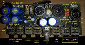
Attachments
Thanks to both ")
That said, the schematic posted by Jon Snell is not hybrid at all, signal parth is all tube end to end; Fets are used as audio switches,basically grounding not needed signal to allow selective 2 channel operation.
I bet you will find them once you get to the preamp.
That said, beutiful pictures and step by step troubleshooting
Apologies to Jon, the name of the amp fooled me, I can see valves at the front end but yet to remove it and get involved there. At least I won't have to spend time reverse engineering it and can get on with the servicing. Many Thanks Jon, I did receive an e-mail from Carlsboro today stating they have no circuit diagrams for any early equipment.
Does anyone have information as to what the bias current should be set to?
I only deal normally with home hi-fi amplifiers where the quiescent current for EL34 output is set to around 35mA. Would this bias level be acceptable to an instrument amplifier or should it be set higher?
I only deal normally with home hi-fi amplifiers where the quiescent current for EL34 output is set to around 35mA. Would this bias level be acceptable to an instrument amplifier or should it be set higher?
- Status
- This old topic is closed. If you want to reopen this topic, contact a moderator using the "Report Post" button.
- Home
- Live Sound
- Instruments and Amps
- Carlsboro Sidewinder 60Watt All Tube Amplifier.