Very pedantically, I would say. Keeping the guitar volume set to 100% at all times removes quite a lot of expressive possibilities for the guitarist. Most good guitar teachers say that leaving the guitar volume always full-up is a bad beginner habit, one that every electric guitar player should strive to overcome. The same applies to the guitar's tone controls.Rotating the guitar pot to 100%, and using a nowadays accepted 10k stopper removes that additional noise source, so pedantically there is something that can be done
This is particularly true when using a valve guitar amp, as the guitar volume pot then controls amp overdrive and therefore affects timbre, as well as its usual function of affecting dynamics.
Here's a video clip of Joe Bonamassa giving a little lesson on the importance of using guitar controls. At roughly 55 seconds into the clip, he gives a striking demonstration, going from Eric Clapton's distorted "woman tone" to Wes Mongtomery's clean jazz tone, using nothing but the volume knob: YouTube
Reducing the input grid stopper to 10k is certainly in the cards, but will have less benefit in an EF86 input stage which is inherently noisier than a half-12AX7 due to partition noise. I'm not sure if the resulting hiss reduction will be big enough to be even audible. IMO, reducing hiss by a decibel or two is hardly a worthwhile improvement. Ten dB would be quite significant, but we won't get that by reducing the 68k resistor.
Most crucially, ElusiveMoose hasn't mentioned a problem with excessive hiss. Unless that changes, IMO it's a case of "don't fix what isn't broken".
I suspect an oscilloscope is not available. A DMM and a good pair of ears are going to have to be the primary development tools, unless I'm mistaken.With respect to the amp at hand, there is no info from the OP on the gain achieved from each of the main amplifying stages, and what stages may be subject to clipping
One one attenuator is fixed-value, the other two being gain and volume pots. The one fixed attenuator replaces a 10:1 passive Baxandall bass stage with a pair of resistors producing the same 10:1 (i.e. 20 dB) attenuation ratio. It's the logical starting point. As I mentioned earlier in the thread, it might need tweaking as the preamp evolves...little in the way of what divider attenuation may be practical
I was expecting e-moose to have issues with the EF86 input stage, which is quite similar to the notoriously problematic one VOX used in their early AC-15. But so far, he doesn't seem to have been plagued by microphony, excessive gain, and premature overdrive due to lack of input headroom - at least, he hasn't mentioned those issues.There are also many simple options for effectively doubling and halving section gains (compared to what the existing schematic shows)
"Overpowering bass" is how e-moose described the current sound. I agree, clearly bass frequency response will need addressing before this preamp design is finished....doing some bass control, via adding/subtracting cathode decoupling.
Again, the OP is taking the "one step at a time" approach, which makes sense for someone starting out with his first guitar preamp. You, on the other hand, already have lots of expertise and experience under your belt. So for you, it makes more sense to rip the whole thing apart and re-engineer it from scratch to suit your taste.
If you have specific suggestions on cap changes to help control bass, why not give them? I'm sure E-Moose would be glad to get input from an experienced guitar amp builder.
-Gnobuddy
> makes no sense at all to first divide down a signal with a pair of resistors, then amplify it back up
Yeah, but.... non-linearity is sometimes useful.
Even "Fidelity". An ideal FM radio ignores amplitude variation. In tubes, this means a last-IF stage working on reduced voltage. But that does not clip dead-flat. In chips it becomes economical to have a *cascade* of clipping stages. Weak signals only clip the last stage. Stronger signals clip more stages, which makes a flatter output, without pushing later stages off their design bias.
In a variation, each stage has a little linear AM detector. First the last stage rises say 0 to 5V. It saturates, but the stage before rises 0 to 5V. Do this for every stage, sum them, you get a wide-range "S meter" which can cover 50+dB of signal on a 50 cent meter. And it works out that for good overlap and good approximation of log response, each stage should have gain of 6dB to 10dB. This could be said to be using non-linearity to give linear-in-dB, without fancy log-amps or costly tapered meters.
It seems to be true that guitarists like such a chain, with gains of about 6dB per stage, with some EQ variation between stages. This gives a "layered" distortion, similar to a voice's sotto - sing - scream, or the layers of over-blow in wind instruments. Because no normal tube gives gain of 6dB, and because we need grid-blocks to prevent blocking, and because 12AX7 grow on trees(?), we normally build a chain of stages with pretty hefty cuts between. One fearful amplifier had 7 or 9 such in a row.
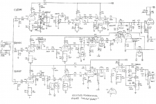
Perhaps the Bogner Fish, aka, the Bogner Triple Giant, possibly also aka the Hafler Triple Giant? It contains 12AX7s by the bushel. I counted 14 triodes in the attached schematic, or 7 12AX7s. Leonidas Fender must have rolled over in his grave....because 12AX7 grow on trees(?)...One fearful amplifier had 7 or 9 such in a row.
-Gnobuddy
Attachments
This is the case. I’m going by ear on a lot of this, but I do have good ears for it and a pretty good idea of the things I’m listening for. As far as which stages of the preamp are more prone to overdriving, I can make some educated guesses using my ears here as well. Triode distortion is easy to pick out if you know what you’re listening for. We’ve all heard amps with all triode preamp stages when the master volume has been turned down and all the overdrive is coming from preamp gain alone. It sounds a little fizzy, and somewhat hollow, it misses the substance and balls and extra sweetness added by the output tube overdrive. Pentode gain in a preamp sounds a little closer to power tube distortion, it’s a little more present, a little girthier and a little sweeter. It still misses the power tube overdrive if you dial down the master volume, but not as much. I’d say after playing it that right now, before starting any TS mods, I’m getting a little distortion in the pentodes and triodes, but more so in the triodes than the pentodes.I suspect an oscilloscope is not available. A DMM and a good pair of ears are going to have to be the primary development tools, unless I'm mistaken.
In addition I’d say that any distortion from the pentodes is probably in that first input stage as that’s the only place in the preamp that I’ve modified the signal chain (the increased 1M grid leak resister and the 47K grid stopper). The second pentode circuit is completely unchanged so it will amplify any distortion in the signal from the first pentode, but it probably won’t add any distortion to it, as it passed on a clean signal all the way to full volume before I started modding. I’d guess the rest of the distortion in the amp has to be coming from the triode stages and the output tubes where I’ve done the bulk of the circuit modifications. Right? Or at least this is the conclusion that my limited knowledge is leading me to, and my ears seem to be backing that up.
")
Last edited:
I thought I’d mentioned but maybe that was on the other forum I’m posting to... I’ve found some nifty adapters that allow me to plug 6AU6 pentodes in where the EF86’s were designed to go. They’re close enough in similar properties to the EF86’s that the amp doesn’t know the difference and the gain they provide is about the same. Also they are cheaper and much less prone to microphony.I was expecting e-moose to have issues with the EF86 input stage, which is quite similar to the notoriously problematic one VOX used in their early AC-15. But so far, he doesn't seem to have been plagued by microphony, excessive gain, and premature overdrive due to lack of input headroom - at least, he hasn't mentioned those issues.
If you have specific suggestions on cap changes to help control bass, why not give them? I'm sure E-Moose would be glad to get input from an experienced guitar amp builder.
All this input is appreciated. I am taking the one step at a time approach because I’m learning on the go, and also because I don’t want to inadvertently design out a part of this amp that could make it unique or different in a good way. Just ripping everything out to make it a more traditional guitar amp circuit might bypass an interesting or useful quirk in design that yields something good here. If I’d wanted a totally traditional sound I would have just bought a diy amp kit for a well known circuit. That said all input is very welcome, even if it’s not advice I use in this mod, having people that know where to look for parts of the circuit that may be troublesome is my whole reason for posting here.
Perhaps your ears are more capable than mine, but to my ears, a small signal pentode can produce quite a wide variety of sounds, depending on the other components connected to it....Pentode gain in a preamp sounds...
If the anode load is low enough to put the load-line "above the knee", for small inputs the distortion sounds a lot like an unclipped triode to me, very much like a Fender clean Blackface amp, but more "valvey".
Other values of screen grid voltage and anode load produced very different sounds, from not-bad overdrive to hoarse and unpleasant distortion, to blubbering and sputtering blocking distortion.
I also found some values of screen grid resistor / screen grid bypass cap that produced very noticeable envelope-shaping: the guitar signal "ducks" a little immediately after each pick attack, then bounces back, sounding almost as if you're using an echo pedal.
This effect is related to the RC time-constant of the screen grid resistor and attached capacitor - the pick attack drives the pentode hard enough to increase screen grid current, which sucks current out of the screen grid bypass cap, which drops screen grid voltage, which drops voltage gain, which makes the signal "duck". As the signal starts to die down a fraction of a second later, the process reverses, the screen grid voltage rises, the gain bounces back up, and so does the guitar signal, causing the illusion of an echo from a delay pedal.
Measuring the quiescent DC voltage at the cathode of the input stage might give us a hint. If the peak signal from your guitar is comparable to or bigger than that cathode bias voltage, the guitar is most likely going to overdrive the input stage....any distortion from the pentodes is probably in that first input stage...
That original EF86 input stage was never designed to cope with the relatively large signal from an electric guitar pickup, so this is quite likely to be the case.
You're in a tough spot, because IMO it's really hard to know what's going on in a guitar amp without a 'scope of some sort (I've tried, and didn't get far.)
For low-voltage audio circuits, it's possible to use the sound-card in a PC (or better, laptop) as an oscilloscope (Soundcard Scope, Sound Card Oscilloscope | Make: ). But safety issues (both for you and the PC) make this a bad idea for valve circuitry containing hundreds of volts.
-Gnobuddy
Sorry, I believe you did post that here. I misremembered that as being part of a different thread. My mistake!I thought I’d mentioned but maybe that was on the other forum I’m posting to...
-Gnobuddy
I’m a musician and I have learned how to use and trust my ears probably more than the average person, but I think we’re all capable of hearing more than we realize once we train ourselves to differentiate what we’re hearing. Don’t sell your own ears short ;-). You note that even when sounding close to a triode that pentodes are “more valvey”. I think we’re actually saying the same thing there but using different language. As close as they can sound to triodes, pentodes always sound different to me, even when they’re not driven hard and especially in direct comparison.Perhaps your ears are more capable than mine, but to my ears, a small signal pentode can produce quite a wide variety of sounds, depending on the other components connected to it.
If the anode load is low enough to put the load-line "above the knee", for small inputs the distortion sounds a lot like an unclipped triode to me, very much like a Fender clean Blackface amp, but more "valvey".
.Other values of screen grid voltage and anode load produced very different sounds, from not-bad overdrive to hoarse and unpleasant distortion, to blubbering and sputtering blocking distortion...
I do understand the overall point you’re making, but I wasn’t trying to generalize that I could pick pentodes out no matter what shape the circuit is in. In this particular instance though, there is no horse distortion, and no blocking distortion even with all the excessive bass in the signal. It really stays pretty clean up to 7/10 on the dial so it’s not too hard to hear things once the breakup does start happening. I’d wager you could hear quite a bit yourself if you had to diagnose the circuit with no scope for voltage probing. I’m not saying it’s the easiest or even best way to do it. In fact I’m sure it’s not lol, but with an amp like this where it’s closer than not to where it will end up I do think it’s doable just making the changes and listening for what I want and don’t want. I suppose we’ll find out whether I’m right or not haha.
Actually the original design was meant to work with high impedance micophones, there are the stepdown transformers that don’t make the original hand drawn schematic but are mentioned just before the input pentodes. Originally I played guitar through one of these and the signal stayed clean all the way to 10/10 volume. Then I bypassed the transformer hoping for overdrive, but it still stayed clean up to 9/10 and only the tiniest bit of break up was there. I did not get any of the distorted breakup you hear in the test videos until I finished the first round of modifications to the circuit. This is another reason I believe most of the breakup is occurring in the power tubes and triodes where the most of my tinkering has been done. Also remember the voltage divide, made by the 1M resisters after all three input stages and the 1M grid leak resister at the second pentode, is attenuating the signal quite a lot. Another reason I think if we have pentode overdrive it’s in the first stage and not the second. Again, you’re absolutely right that the only way to know for sure is to get some measurements at different points in the circuit, but I think we have enough info for the educated guesses I’m making. Of course I could be totally wrong haha, I’m definitely learning as I go here.That original EF86 input stage was never designed to cope with the relatively large signal from an electric guitar pickup, so this is quite likely to be the case.
When I worked out the equations for the cathode bypass cap frequency response, I also wrote some Python code to calculate and display the corresponding frequency response. I think that code is still on my home computer (I'm at work now). If you want, I can run that code for the 6FQ7 parameters, and find out what sort of range of cathode bypass caps is likely to be useful in your amp. (It probably won't be the same values typical in amps using 12AX7 triodes, because gm,mu, and ra are all very different for the 6FQ7.)
Gnobuddy,
Is the offer for calculating this data when you have the time still on the table? If so I would like to take you up on it now actually. I’m going to order some parts online later this week for this and another project and I might as well get everything I need for splitting the 6FQ7 cathodes now. Even if I don’t end up doing it it will only cost me for the couple of 3k resisters and whatever caps, which may be useful on a future project. But also I’m thinking they should be split anyway to avoid any future ill effects from the positive feedback loop in the circuit there. It hasn’t caused problems yet but it would be a bummer for that to start howling later when it’s so easy to split the cathodes and avoid any trouble there now.
> calculating this data
Cathode Bypass Capacitor Calculator at AmpBooks
I don't know that this is exactly right in all extreme cases; I think I have forced it off the rails with silly inputs. But typical inputs give reasonable answers within the precision a stage-amp needs.
6FQ7 is a heavy-duty 12AU7, use that. The other default values are close enough to rock.
10uFd is about as cheap as electrolytic caps get, and is more than ample for full guitar bass.
The typical alternative is about 0.68u as used in many Marshalls to shave the bottom octave, put less power in competition with the bassist and more up in the guitar's voice registers.
0.05u gives a top-rise, which is often part of a guitar amp, but too much of that makes ice-pick ear-bleed.
It is indeed.Is the offer for calculating this data when you have the time still on the table?
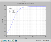
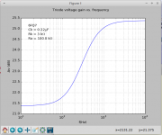
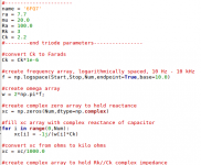
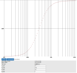
See the attached images. The fifth one is a scrap of my Python code that generated the first four plots. The last image is a screen capture of the 'Web calc that PRR linked.
There's pretty good agreement between the results from my Python program, and the results from the online 'Web calculator. The omission of any y-axis scale in the online calculator seems inexplicable, though.
We can discuss what these graphs might mean in the next post.
-Gnobuddy
Attachments
So what can we glean from those graphs?
The first thing to notice is that, with this particular valve, and these particular anode and cathode resistors, there isn't a huge increase in gain between the low-frequency plateau, and the high-frequency one. In fact, there is only a rise of about 4 decibels. That's enough to definitely be audible (with the right cap values), but not tremendously so.
The second thing to notice is that 2.2 uF is all it takes to give you *full* bypassing down to the guitar's lowest note. Bass response is down only about half a decibel at 80 Hz - which is completely inaudible. In fact, by the standard audio engineering definition (the frequency at which the response falls by 3 dB), the bass cutoff frequency is down at about 20 Hz!
(As an aside, the fact that I keep using oddball preamp valves - and they need different cathode bypass cap values than the ubiquitous 12AX7's - was my primary motivation for working out the relevant math and coding up my little frequency response simulation program.)
Now look at the Ck=1uF curve. Bass response is only down about 1.5 dB at 80 Hz, and down 3 dB at around 40 Hz. Realistically, this is still fully bypassed for guitar, and is even adequate for four-string bass guitar.
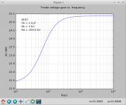
The next smaller cap value (470nF, or 0.47uF) is interesting. It puts the sloping part of the frequency response mostly between 80 Hz and 400 Hz, in the meaty part of the guitar's frequency range. You should hear this as a reduction in that "overpowering bass" you described earlier.
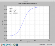
Finally, the smallest cap I tried, 220nF or 0.22uF. This has a gently rising response from 100 Hz to 800 Hz or so, and should produce even more reduction in bass. Only your ears can tell you if this is too much reduction in bass, just right, or not enough.
Bottom line: you do not need a cap bigger than 2.2 uF under any circumstances. I think you're going to find the cap values that sound best (by reducing the excessive bass) will be somewhere between 1uF and 0.22 uF.
I would be tempted to get two each of 1uF, 0.47uF, 0.22uF, and 0.1uF, and then just try them one at a time to find what you like best. They don't need to be exotic or expensive - only a few volts will ever appear across these, and cheap 25-volt rated ceramic caps are perfect for the job.
As an example, this lovely 1uF, 25V multi-layer ceramic cap costs a whopping 65 cents (American): RDEC71E105K0M1H03A Murata Electronics | Mouser
By the way, you can safely ignore fairy-tales about ceramic capacitors creating audible distortion that mysteriously never shows up on actual measurement equipment. I've happily been using multi-layer ceramic caps like this for cathode bypass caps for a few years now. IMO, they're perfect for the job: durable, excellent high-frequency characteristics, better tolerances than electrolytics, no electrolyte to dry up, small physical size, etc.
The only real downside to these ceramic caps is their tiny size (not much bigger than a match-head, if you remember those.) Perfect for PCB mount, a little small for tag-strips.
-Gnobuddy
The first thing to notice is that, with this particular valve, and these particular anode and cathode resistors, there isn't a huge increase in gain between the low-frequency plateau, and the high-frequency one. In fact, there is only a rise of about 4 decibels. That's enough to definitely be audible (with the right cap values), but not tremendously so.
The second thing to notice is that 2.2 uF is all it takes to give you *full* bypassing down to the guitar's lowest note. Bass response is down only about half a decibel at 80 Hz - which is completely inaudible. In fact, by the standard audio engineering definition (the frequency at which the response falls by 3 dB), the bass cutoff frequency is down at about 20 Hz!
(As an aside, the fact that I keep using oddball preamp valves - and they need different cathode bypass cap values than the ubiquitous 12AX7's - was my primary motivation for working out the relevant math and coding up my little frequency response simulation program.)
Now look at the Ck=1uF curve. Bass response is only down about 1.5 dB at 80 Hz, and down 3 dB at around 40 Hz. Realistically, this is still fully bypassed for guitar, and is even adequate for four-string bass guitar.
The next smaller cap value (470nF, or 0.47uF) is interesting. It puts the sloping part of the frequency response mostly between 80 Hz and 400 Hz, in the meaty part of the guitar's frequency range. You should hear this as a reduction in that "overpowering bass" you described earlier.
Finally, the smallest cap I tried, 220nF or 0.22uF. This has a gently rising response from 100 Hz to 800 Hz or so, and should produce even more reduction in bass. Only your ears can tell you if this is too much reduction in bass, just right, or not enough.
Bottom line: you do not need a cap bigger than 2.2 uF under any circumstances. I think you're going to find the cap values that sound best (by reducing the excessive bass) will be somewhere between 1uF and 0.22 uF.
I would be tempted to get two each of 1uF, 0.47uF, 0.22uF, and 0.1uF, and then just try them one at a time to find what you like best. They don't need to be exotic or expensive - only a few volts will ever appear across these, and cheap 25-volt rated ceramic caps are perfect for the job.
As an example, this lovely 1uF, 25V multi-layer ceramic cap costs a whopping 65 cents (American): RDEC71E105K0M1H03A Murata Electronics | Mouser
By the way, you can safely ignore fairy-tales about ceramic capacitors creating audible distortion that mysteriously never shows up on actual measurement equipment. I've happily been using multi-layer ceramic caps like this for cathode bypass caps for a few years now. IMO, they're perfect for the job: durable, excellent high-frequency characteristics, better tolerances than electrolytics, no electrolyte to dry up, small physical size, etc.
The only real downside to these ceramic caps is their tiny size (not much bigger than a match-head, if you remember those.) Perfect for PCB mount, a little small for tag-strips.
-Gnobuddy
Gnobuddy,
Thank you for the great data! Really comprehensive as usual, just what I needed.
Thank you for the great data! Really comprehensive as usual, just what I needed.
And boy am I glad you did haha! A question on this tangent, which oddball preamp tubes have you found that you enjoy working with the most? Not asking for this build btw, I'm just curious what you've come across while trying different tubes and which ones yielded the most success.(As an aside, the fact that I keep using oddball preamp valves - and they need different cathode bypass cap values than the ubiquitous 12AX7's - was my primary motivation for working out the relevant math and coding up my little frequency response simulation program.)
Just what I was thinking as I looked through your results. I believe I'll start at 1uf first and see where that puts us after finishing the TS mod. We will loose a bit of low end in the signal from the coupling cap we put where the old bass control was located and the new Fender style TS will certainly sound a bit different in the low end too. Also the mid scoop in the Fender style TS will make things sound very different as well. I don't want to kill too much bass, but I do want it to be at a level where the bass control can reasonably effect the amount of bass we hear.I would be tempted to get two each of 1uF, 0.47uF, 0.22uF, and 0.1uF, and then just try them one at a time to find what you like best.
Good to know!By the way, you can safely ignore fairy-tales about ceramic capacitors creating audible distortion that mysteriously never shows up on actual measurement equipment.
You're welcome! I hope one of those values turns out to be what you need.Thank you for the great data!
As a preamble, I'm extremely skeptical that there are only a few expensive magic valves filled with mystic mojo.which oddball preamp tubes have you found that you enjoy working with the most?
As long as the valve parameters (gm, mu, voltage ratings, etc) are in the right ballpark, we should be able to use any of them. We can change how they sound by altering component values and signal levels. They won't all sound exactly the same when overdriven, but that's fine. Music needs variety to be interesting anyway.
So I've been tinkering with unloved NOS valves that cost $1 each from ESRC Vacuum Tubes ( Summer Dollar Days - Vacuum Tube Sale - $1.00 Vacuum Tubes ).
So far I've had reasonable success with the 6JW8 (triode and small-signal beam tetrode in one bottle), 6AG5 (small-signal beam tetrode), and 6AQ6 (triode plus two useless diodes). By "reasonable success", I mean that all of them amplify and work just fine for clean tone, but I haven't managed to get all of them to sound good when overdriven, which I'm sure is entirely my fault, not the valve's.
If you have a graphic EQ pedal for your guitar, you can use it to get a "preview" of what different frequency responses sound like.Also the mid scoop in the Fender style TS will make things sound very different as well.
About a year and a half ago, I was struggling with a solid-state guitar amp design that sounded harsh. Using my cheap and ugly Danelectro Fish-n-Chips graphic EQ pedal, I quickly found out that a notch a few dB deep at around 800 Hz went a long way towards taming the harsh sound. I think it would have taken me ten or twenty times as long to discover that by the more traditional methods of swapping caps and resistors and tone-stacks in the hope of finding something that sounded good.
Sure, makes sense. Are you still interested in finding out what the stock James bass control does? Or are you pretty much committed to the change to a Fender tone control circuit?I don't want to kill too much bass, but I do want it to be at a level where the bass control can reasonably effect the amount of bass we hear.
-Gnobuddy
Good tip!If you have a graphic EQ pedal for your guitar, you can use it to get a "preview" of what different frequency responses sound like.
That is a good question haha. I'm curious about it yes, but I'm also pretty sure that there will be no way to get enough of a mid scoop with the current James TS configuration, so just modding the cap values to see how it sounds might be a fruitless endeavor. I never went back to finish my LTSpice schematic of the whole TS for testing either, but again I have not yet seen ANY version of a James TS that would get the sound I think I want to go for. So as the saying goes; why try to make an apple sound like an orange when you can just make an orange instead?... Or something like that lolAre you still interested in finding out what the stock James bass control does? Or are you pretty much committed to the change to a Fender tone control circuit?

Understood. I have a foot in both camps - the audio engineering camp and the musician camp - and I can say with confidence that, while our ears are wonderful at all the tasks evolution required for our survival (which includes music and speech), they stink as precision measurement tools!I’m a musician and I have learned how to use and trust my ears probably more than the average person
So I can usually hear a guitar second string (open B) that's 20 cents sharp on one guitar out of five across the room at a jam, and gently remind the player that it's time to pull out his/her Snark.
But if you put a 1-dB notch in my guitar amp frequency response and ask me what frequency it's at, I probably wouldn't even be able to hear it, never mind tell you what frequency it's at. (A 1 dB loudness change is right at the threshold of detectability for the human ear).
Even the cheapest fifty-cent electret microphone would have no trouble at all identifying the notch, though. That's one situation where our ears are just not suitable for the task.
Honestly, I don't think I am. For an amateur musician, I know I have pretty good ears - for those things human ears are actually good at.Don’t sell your own ears short ;-).
But I try not to make the opposite, and far more common, mistake: believing I can hear things that I cannot, in fact, hear.
(Just pop over to neighbouring forums right here on diyAudio for plenty of examples of people who're convinced they can hear all sorts of absolutely ridiculous things, including the "sound" of the coloured insulation on a signal-carrying wire.)
I believe that's true for me as well. But now you've made me want to build a pentode circuit that sounds indistinguishable from a triode.As close as they can sound to triodes, pentodes always sound different to me, even when they’re not driven hard and especially in direct comparison.
(It may not be much of a challenge, particularly if the pentode is wired in triode-mode!)I started out building and tweaking my little 2-watt 6AK6 push-pull amp without a 'scope. I did eventually get it to produce a nice singing / shimmering "valvey" clean tone, still without a 'scope.I’d wager you could hear quite a bit yourself if you had to diagnose the circuit with no scope for voltage probing.
But it took quite a while to get there, and when I eventually did get a 'scope, I was able to quickly correct some remaining problems (mainly with how it sounded at the onset of overdrive.)
-Gnobuddy
Great, now you've made me want an orange!...why try to make an apple sound like an orange when you can just make an orange instead?...
-Gnobuddy
I think wiring as a triode would be cheating lolnow you've made me want to build a pentode circuit that sounds indistinguishable from a triode. (It may not be much of a challenge, particularly if the pentode is wired in triode-mode!)
 , but also I'm curious if a difference would still be audibly distinguishable in triode mode... I'm aware of a few circuits that do this, but I don't believe I've heard any in person.
 That's the trouble with food related analogies... they always leave you hungry for moreGreat, now you've made me want an orange!
I will probably have to remedy this situation and buy some scoping equipment sometime sooner than later, but I'll see where I'm at after this upcoming round of mods. I think the amp is close to being usable and I'm very hopeful that the Fender style TS is going to be a success... Of course optimism is always easier for a newbie, haha.I started out building and tweaking my little 2-watt 6AK6 push-pull amp without a 'scope. I did eventually get it to produce a nice singing / shimmering "valvey" clean tone, still without a 'scope.
But it took quite a while to get there, and when I eventually did get a 'scope, I was able to quickly correct some remaining problems (mainly with how it sounded at the onset of overdrive.)

- Status
- This old topic is closed. If you want to reopen this topic, contact a moderator using the "Report Post" button.
- Home
- Live Sound
- Instruments and Amps
- Need PA amp conversion help