Right just like the old errantly named Fender "Vibrato" circuits. I do like the way those Fender LDR circuits sound, but I think the Bias Wiggle method will be the best bet for my amp in this case.There is at least one other very different (and slightly less ancient) approach to tremolo, which is to insert some sort of circuit element in the signal chain, and vary its value cyclically. Often the variable element was an LDR, a light dependent resistor (now becoming scarce, and never famous for reliability). A small light bulb or LED positioned right against the LDR is driven by the tremolo oscillator, and the fluctuating light varies the LDR resistance, causing the tremolo effect as the guitar signal goes through it.
These were all good points for sure so I went in search of answers last night. I ended up finding a great demo of an amp that uses wiggle bias trem and a single knob to control speed while depth is set to a kind of low-medium setting with a fixed resister value. It's one of those kooky pawn shop series amps that Fender made a while back lol. I think I actually like the sound and functionality of it. I have several trem effects I can run through pedals if I need to dial in more depth for a specific sound, but as a quick effect to just throw on and add some texture I think the speed only knob set up would be fun to have"bias wiggle" tremolo... I suspect this may only work well when the output stage is running clean (not distorting), otherwise it will sound like wiggling the gain knob on your distortion pedal... My two cents is that you will be happier with two knobs, by whatever method possible. I think there will be times when you want the tremolo slow and deep, or slow and shallow, or fast and deep, or fast and shallow, and a single pot won't allow you this sort of creative freedom.
") . Also it seems to work fine while the amp is overdriving so that's another worry to check off the list
. Also it seems to work fine while the amp is overdriving so that's another worry to check off the list 
YouTube
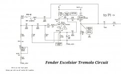
Schematic for the Fender Excelsior amp and a blow up of the trem circuit are attached below. I think I'll go to work on this soon using the silvertone trem schematic I found earlier to draw up my own pentode wiggle bias trem circuit with a fixed resistor for depth. I may play with the schematic more before actually trying to wire anything into the amp, but this looks like a good place as any to start.
Attachments
Excellent, that makes life easier. I didn't expect that....it seems to work fine while the amp is overdriving...
I remember the introduction of the Excelsior. I even looked at one briefly in a music store. It was very heavy. Clearly Fender didn't scrimp on the amount of MDF in the cabinet.
Maybe use a trimpot that you can set and forget?...with a fixed resistor for depth.
-Gnobuddy
Haha yep, a 13 watt amp with a 35 LB curb weight lol. Made in China so they were trying to go cheap as possible with materials I suppose.I remember the introduction of the Excelsior. I even looked at one briefly in a music store. It was very heavy. Clearly Fender didn't scrimp on the amount of MDF in the cabinet.
Good idea!Quote:
Originally Posted by ElusiveMoose22 View Post
...with a fixed resistor for depth.
Maybe use a trimpot that you can set and forget?
Last edited:
How's that tremolo oscillator coming along? Any progress?
-Gnobuddy
I had some other things come up over the weekend and wasn't able to set aside any time to work on it. Looks like I might not be able to work on it for the next few weeks
. But I will get back to it soon as I can and post an update then!I only have the 1 volume pot on the third channel free to control trem oscillation. Anyone have success designing a 1 control knob trem system?
Yes, through the magic of a coaxially stacked potentiomter. (see the Rod Elliot article)
One of them for speed (outside/back) and the other depth (front/inside)
E.g. Fender 0019268000 250k/500k as used in the jazz bass or similar (from Alps or others). Some of the old ones used to have a switch as well (which used to be used for the power switch)
I also remember a Gibson amp which had trem via wiggling the input pentode. For the life of me I can't remember whether it wiggled screen, plate or kathode...
but Fred Nachbaur did something for his compressor ... and you can turn a compressor into a tremelo by feeding the control voltage with a wiggle
Last edited:
Yes, through the magic of a coaxially stacked potentiomter. (see the Rod Elliot article)
One of them for speed (outside/back) and the other depth (front/inside)
E.g. Fender 0019268000 250k/500k as used in the jazz bass or similar (from Alps or others). Some of the old ones used to have a switch as well (which used to be used for the power switch)
I also remember a Gibson amp which had trem via wiggling the input pentode. For the life of me I can't remember whether it wiggled screen, plate or kathode...
Thanks for the references thoglette
I'm currently working a new reel-to-reel amp conversion modeled after the old Vox AC4 design which has a tremolo with fixed depth and adjustable speed too. I'd planned on finishing that and coming back to this project after, but the coaxially stacked pot could be useful in the reel-to-reel conversion project as well
Now that it's been a few weeks, may I request that you post a schematic of the amp in its final form? Pretty please?
I'd love to know the end result of some of those discussions we had, and how some of those test-by-ear values turned out. For instance, what cathode bypass cap values did you actually end up using on the preamp triodes, and did you have to change the fixed attenuation (two resistors between pentode and triode), and so on.
A schematic of the amp as it ended up will answer all those questions.
-Gnobuddy
Now that it's been a few weeks, may I request that you post a schematic of the amp in its final form? Pretty please?
I'd love to know the end result of some of those discussions we had, and how some of those test-by-ear values turned out. For instance, what cathode bypass cap values did you actually end up using on the preamp triodes, and did you have to change the fixed attenuation (two resistors between pentode and triode), and so on.
A schematic of the amp as it ended up will answer all those questions.
-Gnobuddy
With pleasure! Please see attached
This is a quick mock-up from memory but I'm 99% confident this is how it all sits at the moment.
As to the answers for the questions mentioned specifically above:
1.) I went with .1uF caps for the cathode bypasses on the triode before and after the tone-stack. I wanted a value that was still fully bypassed for the guitar's low end as was worried I might loose too much bass with some of the other changes, and boy was I right! In fact, at the first test, I found so much bass had been lost that I was worried I'd done something wrong. Review showed I hadn't made any errors so I went back to coupling cap C19 which I had also changed to .0047uF at your suggestion. I put the original .02uF value back in just to see what that did and the bass response was perfect
 . At that point I decided to leave well enough alone, a decision I'm still happy with.
2.) Your suggested resister values to attenuate between the 2nd preamp pentode and the first triode were right on the money
 ! There is still enough gain to drive the triodes when you push the input volume, but with the master volume set anywhere from 7-10 there is plenty of clean headroom left in the amp before breakup starts.
If you have any other questions about the schematic or how the amp ended up please ask and I'll do my best to answer. I do plan on coming back to this one again, when I finish my current reel-to-reel project and time allows, and I'll turn the second pentode input into a tremolo driver of some kind... I'll update the schematic again once I start that project.
In the meantime here is one last quick vid from a bit ago with some noodling to test volume response and dynamics in the amp. Forgive the meandering and aimless playing, but the amp itself sounds pretty good no?
YouTube
Attachments
Thank you!With pleasure! Please see attached
Hmm, the new schematic shows 1uF, not 0.1uF? Can you please verify which one you ended up using?1.) I went with .1uF caps for the cathode bypasses
Back in post #54, the simulation suggested 1uF would cause very little bass-cut. But 0.1uF would certainly cut the bass quite a bit.
Wise man!...I decided to leave well enough alone...
Indeed! Lots of "tubey" character, for sure. It sounds a bit light on bass to me, but because of that, I bet this amp "sits well in the mix". Am I right?...the amp itself sounds pretty good no?
-Gnobuddy
Yeah that was a typo on my post sorry! The Schematic is correct, I used 1uF caps.Hmm, the new schematic shows 1uF, not 0.1uF? Can you please verify which one you ended up using?
Correct, I believe I have Treble set at 6.5 and Bass set at about 3.5-4 in this vid. That’s probably pretty close to how I’d run it for a gig, maybe a little less treble at higher volume actually. I still have not gigged it yet, my last guitar gig was outdoors and I didn’t want to put the vintage transformers through that for a first time out. All subsequent gigs have all called for me to be on bass, including this upcoming weekend. I believe I will be playing some guitar next Thursday though so I may get the chance then. I think it will sit pretty well in a full band mix. The mids are fairly scooped, per my design, so it may get lost a bit on rhythm parts, but on leads that’s what Klon and Tube Screamer type pedals are forIt sounds a bit light on bass to me, but because of that, I bet this amp "sits well in the mix". Am I right?
Thanks for clarifying that. I'm a little surprised that the 1uF caps made such a big difference to the bass - I wasn't expecting that from the simulation. Good thing we have reality to correct our simulations!The schematic is correct, I used 1uF caps.
Another reason to like Crowded House - Nick Seymour, their bass player! I like a lot of his complex, weaving, melodic lines, and I think he added a lot to the group's sound.All subsequent gigs have all called for me to be on bass
-Gnobuddy
Huge difference! Perfect bass level for me nowThanks for clarifying that. I'm a little surprised that the 1uF caps made such a big difference to the bass - I wasn't expecting that from the simulation. Good thing we have reality to correct our simulations!
, though if I were ever to sell it I might try larger caps just to see how they sound. Maybe fender style 22uF caps so that someone else might have the option to dial in more bass if needed? Anyways, it's good for me now Nice, I've made a playlist of Crowded House songs spanning the albums corresponding to the songs you recommended but I haven't had a chance to listen through it yet. Maybe I'll play it this Saturday while working on my reel-to-reel projectAnother reason to like Crowded House - Nick Seymour, their bass player! I like a lot of his complex, weaving, melodic lines, and I think he added a lot to the group's sound.
Here's a vid to another one of my favorite Wico songs where the bass player (John Stirratt) lays down a nice melodic line that works with the vocal melody the whole song. Those two complementing melodies really tie everything together and make the song work.
YouTube
- Status
- This old topic is closed. If you want to reopen this topic, contact a moderator using the "Report Post" button.
- Home
- Live Sound
- Instruments and Amps
- Need PA amp conversion help