Hi all,
I have quite some experience repairing all kinds of amplifiers (approx. 100 or so during the last 3 years, mixed valve and solid state types), but this one gives me some headaches") . It is a VOX AD 60 VT guitar amp.
. It is a VOX AD 60 VT guitar amp.
I received it as broken, and I saw when running it over a variac there is much too high idle current across the power transistors even on low rail voltages.
As I did not find *any* broken part (except for a defective rectifier which finally gave in, which I replaced in the meantime), I decided I would need to understand the amp better in order to derive what voltages should be where under normal conditions. Unfortunately (as most of the time) the supplier does not provide any info about that.
Seeing that some NF connectors where attached to the wrong posts (mixed up), I am pretty sure someone was already in there, also some solder points did not look like original. So it could also be there is some fault in there that had been added later on.
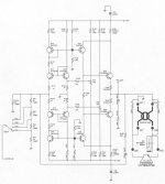
Starting at the Power amplifier input stage, I found this however quite unusual. It is not the standard differential input amp with two transistors with one base connected to the input and one to the feedback plus 2 transistors as a current mirror. It is also not a double input stage. I read Douglas Self but did not find anything like that in his standard book, too.
It looks quite different, and I don't understand yet how it works.
Maybe you would like to comment on this one and make me learn some new things here?
How is this called, and what functions do which transistors fulfill?
Best Regards,
Hajo
I have quite some experience repairing all kinds of amplifiers (approx. 100 or so during the last 3 years, mixed valve and solid state types), but this one gives me some headaches
. It is a VOX AD 60 VT guitar amp.I received it as broken, and I saw when running it over a variac there is much too high idle current across the power transistors even on low rail voltages.
As I did not find *any* broken part (except for a defective rectifier which finally gave in, which I replaced in the meantime), I decided I would need to understand the amp better in order to derive what voltages should be where under normal conditions. Unfortunately (as most of the time) the supplier does not provide any info about that.
Seeing that some NF connectors where attached to the wrong posts (mixed up), I am pretty sure someone was already in there, also some solder points did not look like original. So it could also be there is some fault in there that had been added later on.
Starting at the Power amplifier input stage, I found this however quite unusual. It is not the standard differential input amp with two transistors with one base connected to the input and one to the feedback plus 2 transistors as a current mirror. It is also not a double input stage. I read Douglas Self but did not find anything like that in his standard book, too.
It looks quite different, and I don't understand yet how it works.
Maybe you would like to comment on this one and make me learn some new things here?
How is this called, and what functions do which transistors fulfill?
Best Regards,
Hajo
Attachments
Last edited:
Q15,Q17, Q22, Q24 are used a diodes. I don't know why they didn't use diodes which should be cheaper, but maybe their corporate gurus had an upper limit on number of lines stocked or something. Maybe they didn't want to change head on the pick and place machine from transistor to diodes. Maybe they had some garbage transistors that failed incoming inspection that they didn't have to pay for. Each shorted BC transistor having a different part # sure adds to the BS factor.
So the input pair runs .7 v less than the power supplies, so it won't saturate anything later. Weird setup, I don't know how it respond if the input signal were less than 1.4 v, not put anything out I suspect. Q22, Q24 put the drive tothe VAS 1.4 v apart so the two VAS transistors both conduct.
Q23, Q25 are the VAS, voltage amplification stage. Running two VAS off the two outer rails is something Peavey does in the CS800 rev C for example.
Q26, Q29 are emitter followers, the output transistors.
Last edited:
It's new to me as well, but I think I figured out how it works (mostly!)It looks quite different, and I don't understand yet how it works.
Starting at the output, Q28/Q23 behaves like a Sziklai pair ( Sziklai pair - Wikipedia), basically like a single PNP power transistor with very high current gain. However, the Sziklai pair is not wired as an emitter follower: instead, it is an inverting gain stage. The "collector" of the Sziklai pair drives the loudspeaker, and R102? (the 0.68 ohm / 5W resistor from Q28 to the +47V rail) provides a little local negative feedback to linearize the Sziklai pair and provide some thermal stability.
Of course, Q25/Q29 is the complimentary Sziklai pair, this time handling negative half-cycles to the load.
R165 (1k) provides a crude bias voltage to Q28/Q29 to reduce crossover distortion at the output. There is no thermal compensation or other refinements, so I'm guessing Q28/Q29 are actually operating in class B, i.e., bias current is zero, but R165 biases them almost on.
Since the loudspeaker is connected to the "collector" of the Sziklai pairs, it is driven by a high impedance, not a low one. This is very different from what you find with solid-state Hi-Fi amps - those almost always have very low output impedance to provide a large "damping factor" for the loudspeaker.
In this circuit, the deliberate high output impedance is almost certainly intended to mimic the behaviour of valve guitar amps. Output stages made with pentodes have very high output resistance, and I think this circuit was designed to have similar characteristics, so the guitar speaker will respond the same way as it does to a pentode (valve) output stage.
So far, so good! Now we have a reasonable understanding of the output stage.
Let's move towards the input of the circuit a little. Q23 and Q22 are wired as a current mirror, with a slight twist: the emitter resistor of Q22 is 330 ohms, while the emitter resistor of Q23 is 0.68 ohms. In operation, the current mirror tries to maintain equal voltage drops across both resistors - and Ohm's law tells you the current through the .68 ohm resistor will be (330/0.68) times bigger, or 485 times bigger.
Rounding off slightly, the current delivered to the loudspeaker will be roughly 500 times the current through Q22.
The circuit is mirror-symmetrical, and Q24 / 25 does the same thing as Q22/ Q23, but this time, for the negative half cycles of the output signal. Notice that R169 / R154 maintains the same ratio of 485, so that, once again, the speaker gets about 500 times as much current as flows through Q24.
This behaviour is, once again, a bit unusual: this amplifier is designed to behave like a current amplifier, rather than the traditional solid-state voltage amplifier. This is because the focus is on the amp behaving like a current source, driving the loudspeaker from a very high impedance.
We're almost home!
Q14/Q15 is another current mirror, but basically it's acting as a level shifter, so that we can conveniently apply our input signal referenced to the ground rail (0V) rather than referenced to the collector of Q22, which is near +47 volts DC. Q16/Q17 does the same thing for Q24/Q25.
And this brings us to the junction of R141/R145. When everything is trimmed out (RV1 / RV2), this point rests at 0 volts. If we apply a small negative voltage here, the current through Q14 increases, and 500 times as much current is dumped into the speaker via Q28. If we instead apply a small positive voltage here, the current through Q16 increases, and 500 times as much current is sucked out of the speaker via Q29.
Which finally brings us to the switch and the mess of resistors at the input. This appears to be a variable current divider. Essentially, if we drive the input (the pole of SW1A) with a small AC signal current, these resistors decide how much of that current makes it to the junction of R145/R141.
Basically, the switch and resistors reduce the current gain of the amp from the value of roughly 500 we calculated earlier. The amount of reduction depends on the switch position. And the amount of current gain of the amp decides how much power goes to the speaker for a given input signal.
It would appear PA1_In is itself a (signal) current, and the resistor values have been chosen so that you get a maximum of 1W of power to the speaker when the switch is in its lowest position, 15 watts in the next position up, and so on. In other words, the switch is designed to meet the expectations of a guitarist familiar with speaker attenuators used with valve guitar amps. (It doesn't actually work anything like a traditional speaker attenuator, though.)
Finally, there is a little AC negative feedback from the output of the amp back to the input, via the 560 ohm resistor (R165?), to lower distortion and reduce the output impedance a little bit (it will still be very high.)
There are a few details I feel I still haven't quite figured out, but I think, for the most part, this circuit works as I've just described.
It's been a long time since I've seen anything novel in a solid-state audio power amp. So it was fun trying to figure out how this one works, because it was certainly novel to me!
-Gnobuddy
Very accurate.
Let me add that this is not a "full" power amplifier by any means, but a current/power booster driven not from a Preamp but presumably (you don´t show that part of the circuit) from a small power amp, coming thrpugh PA1 in.
Would not be surprised at all about finding a small tube power amp driving this stage; after all "tubes are better" and doubly so in the Guitar World.
This configuration would allow a Tube "do its magic" and then the output stage just scales voltage and current up, as needed, to drive a speaker but in principle "maintaining the tube sound".
One hint about that is the quite high (for a 60W amp that is) +/-47V rail voltage; I bet chosen so it never ever clips on its own.
Also note that this power block input impedance is VERY low, with near speaker voice coil values, impossible to drive from any typical preamp:
* 60W setting: R144 62 ohm in parallel with attenuator string R06/05/04/25 , for a total value of around 40 ohm
* 30W setting: around 45 ohm
* 15W setting around 40 ohm and
* 1W setting around 8 or 9 ohm !!!
plus injecting a few mA into Q14/16 emitters.
Tube amps do their best when driven hard, but the problem is than then it becomes "fixed power" ... while this setup allows it to emulate, say:
* 2 x EL34 for 60W (VOX AC50 or similar)
* 4 x EL84 (AC30)
* 2 x EL84 (AC15)
* the 1W one, don´t remember what power tubes they use , but in any case, this allows them to resonably mimic (as far as power is concerned) their most famous models.
Not a bad idea at all.
Valve Reactor amps allow a continuous power adjustment with a potentiometer but cirquit is quite complex, here they seem to jave split the job into 2 separate blocks, each easier to handle.
That said, if you have blown transistors, bias trouble, etc. , that is troubleshooted and solved like in a regular transistor amp.
In principle top and bottom halves are symmetrical and since we lack the self-correcting front end differential pair, they had to add balancing (and probably biasing) adjustment trimpots RV1 and RV2 .
I´d styart by feeding amplifier through a lamp bulb limiter and check voltages, which will show me which transistors are shorted (dropping 0V or 0.7V) or open (they show full voltage across CE yet base is biased 0.7V or more) or open BE (which shows impossible 5 or 10V drop) and so on.
Set all controls to 0, power switch to lowest value (1W) and start measuring DC at the power amp and finding possible bad parts which might be causing that.
And ... good luck
Thanks! You saw a number of things that I missed, though!Very accurate.
That is a very interesting thought. It reminds me of Printer2's "Mini amp for output tube distortion" thread. Perhaps VOX is already doing exactly this?Would not be surprised at all about finding a small tube power amp driving this stage
There's another thing I missed completely. Yes, +/- 47 volt rails can supply considerably more than 60 W RMS to an 8 ohm speaker - in fact, they should be able to supply more than 120 W RMS, assuming a reasonably "stiff" power supply.One hint about that is the quite high (for a 60W amp that is) +/-47V rail voltage; I bet chosen so it never ever clips on its own.
I did notice that part. Evidently the preamp can supply considerable current (for a preamp), and probably has a fairly high output impedance itself. A small pentode stage, perhaps?Also note that this power block input impedance is VERY low, with near speaker voice coil values, impossible to drive from any typical preamp
What a pity we don't have the schematic for the stage that is driving this one!
-Gnobuddy
Looks like J.M. Fahey's hunch was on the mark. I found this interesting link: The VOX Showroom - The Vox Valvetronix "Blue" Series - Valve Reactor Power Amp Overview
Apparently the VOX AD60VT used a 12AX7 as a "one watt" push-pull valve power amp, which in turn drives the 60 watt solid-state amplifier stage.
Squeezing 1 watt out of a pair of triodes which happen to have a very high 60,000 - 70,000 ohm internal anode resistance (ra) seems impossible (except in marketing-land, with some extremely creative engineering definitions.)
I would like to know more details of the push-pull transformer used with the two triodes in the 12AX7. It's hard to imagine getting more than maybe 2 mA (peak) current out of a 12AX7. That must make for a very high impedance transformer, I would think.
I'm no VOX expert, but it seems that traditionally VOX guitar amps have very little bass below 500 - 600 Hz or so, which would make it easier to wind the high-Z transformer (you'd need much less primary inductance than an amp with better bass response.)
-Gnobuddy
I would like to know more details of the push-pull transformer used with the two triodes in the 12AX7. It's hard to imagine getting more than maybe 2 mA (peak) current out of a 12AX7. That must make for a very high impedance transformer, I would think.
There's a discussion on the Fender Music Master over on AussieGuitarGearHeads where both the main and reverb signals have 12AX7s driving transformers.
The main signal path goes into an IT which is badly mismatched w.r.t. the 12AX7 but still seems to work well enough for jazz (or rock, in this case). Current theory is that the IT transformers were cheap so...
It can be a nightmare fixing "got at" amps.
I went around in circles trying to repair an old Maplin amp.
All resistors checked out ok and caps.
I did diode test on all transistors and they were fine.
It half worked and gave out distorted sound.
I kept going back to one transistor where voltages didn't seem quite right.
Then it suddenly hit me, it was an npn instead of a pnp transistor.
That's why it passed diode test.
Just to help me the transistors markings had been worn off.
Replaced wrong transistor and everything was fine.
The only other time I got a really awkward fault was an amp where all transistors diode checked ok. Everything else checked out ok.
In the end I took all the transistors out and Hfe checked them and one of the input transistors had a Hfe of 1 !
Another time I bought in a 1980's Maplin amp with parts missing.
I replaced missing output transistors and the amp was just an oscillator !
The new transistors had wider bandwidth and higher gain compared to originals causing the problem.
I had to increase the VAS capacitor a little to kill the oscillation and everything was fine.
Thanks for the link! In the first video clip, that amp has very interesting overdrive tone, much smoother and less harsh than what I'm used to hearing. I wonder if that's all down to the reduced bias shift and blocking distortion resulting from the interstage transformer coupling?T
...Fender Music Master...both the main and reverb signals have 12AX7s driving transformers.
Not to wander too far off topic, but Tubelab George has been driving his output valves with direct-coupled MOSFETs in some of his designs, which should result in some of the same benefits provided by the interstage coupling transformers - and without the headaches of finding and using actual interstage tranformers today (though you get new headaches to replace them, mostly involving the need for a more complex multi-rail power supply.)
-Gnobuddy
Some, to be certain. All is a harder call: the speaker can/could be providing some of the smoothness. Then there's the microphone and room .....I wonder if that's all down to the reduced bias shift and blocking distortion resulting from the interstage transformer coupling?
Sorry, I was imprecise in my choice of words.Some, to be certain. All is a harder call
-Gnobuddy
Thanks for your great comments
Hello all,
finally, after some months now, I found that there have been quite some great analyses by now (special thanks to Gnobuddy for your deep insights!).
Unfortunately I had relied on some eMail notifications which for some unknown reason never came, so I did not realize them in time.
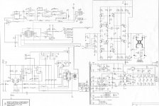
In order to complete this thread, I would like to fulfill the requests of additional schematics. Yes, your expectations were correct, there is actually a 12AX7 driving this stage. Again, I am really impressed about your in-depth knowledge.
Please find the two attachments with one overview and the detailed schematic.
I hope VOX/KORG will not beat me up for this, I found all of them for free in the net, too.
In addition to this - yes I have to agree to another comment here - fixing amps which somebody else was already into adds some unusual things which can be easily overlooked first - as also in this case:
Somebody had already unsoldered some of the input stage transistors for checking - and soldered them back in the wrong positions (!). That cost me a while, too!
Have a great day and please continue your good work here!
Best Regards,
Hajo
Hello all,
finally, after some months now, I found that there have been quite some great analyses by now (special thanks to Gnobuddy for your deep insights!).
Unfortunately I had relied on some eMail notifications which for some unknown reason never came, so I did not realize them in time.
In order to complete this thread, I would like to fulfill the requests of additional schematics. Yes, your expectations were correct, there is actually a 12AX7 driving this stage. Again, I am really impressed about your in-depth knowledge.
Please find the two attachments with one overview and the detailed schematic.
I hope VOX/KORG will not beat me up for this, I found all of them for free in the net, too.
In addition to this - yes I have to agree to another comment here - fixing amps which somebody else was already into adds some unusual things which can be easily overlooked first - as also in this case:
Somebody had already unsoldered some of the input stage transistors for checking - and soldered them back in the wrong positions (!). That cost me a while, too
!Have a great day and please continue your good work here!
Best Regards,
Hajo
Attachments
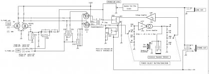
Thanks for coming back with all this extra information!...there is actually a 12AX7 driving this stage.
As suspected, the schematic shows a very high impedance output transformer for the 12AX7. 50k from centertap to each end, or 200k from end-to-end, (twice the windings, four times the impedance), which is the way valve OTs are usually specified. Compare that with the more typical 8k or 6.6k values used in more typical guitar amp output stages!
For us DIY types, a 200k OT is unobtanium. But if a slightly lower ra triode, or better, a pair of NOS tiny pentodes was used instead, the concept becomes do-able. Two little 6AK6 pentodes will drive a 22k (end to end) OT, and that impedance can be found off-the-shelf.
-Gnobuddy
- Status
- This old topic is closed. If you want to reopen this topic, contact a moderator using the "Report Post" button.
- Home
- Live Sound
- Instruments and Amps
- VOX unusual input stage - comments?