I expect they worked just fine in their original application. As you say, they were never designed to amplify the same audio signal through all three devices.But I believe that Compactron was not designed to amplify the same signal in the three sections.
An op-amp has a lot more than 60 dB of gain in an even smaller physical space, but it doesn't have big metal plates acting as antennae to radiate the output signal back to the input.
 And most op-amps now have internal frequency compensation, so there isn't much gain at radio frequencies, which helps to manage any RF instability.
Both Tubelab George and I have used 6JW8 triode-pentode valves in guitar preamps. He put the pentode stage first, and described having some trouble with stability - the layout of the pins puts the triode anode right next to the pentode control grid, so stray coupling will easily cause oscillation.
I put the triode stage first, and had no trouble with stability. In this configuration, the triode output (anode) is right next to the pentode input (control grid), but the pentode output (anode) is some distance away.
It just goes to show that using these multi-section valves for audio is tricky, and can depend unexpectedly on layout and circuit details that wouldn't matter in a more typical design using separate valves in separate bottles.
About the Super Squirrel Monkey - there is a comment on the video about an (external) cathode follower, by which I suspect the builder meant two-triode, DC coupled triode gain stage and cathode follower, a la Fender Bassman.
I am not sure, but it sounded as though the topology was 6AF11 triode -> gain control -> 6AF11 triode -> gain control -> 12AX7 gain stage -> 12AX7 cathode follower -> Tone control circuit -> 6AF11 pentode.
I am curious how the amp remained stable with the additional gain from the 12AX7. However I note that there would be an additional phase inversion from the 12AX7, which might have cured the positive feedback oscillation from internal stray capacitance. It probably also helped to have two gain controls, to reduce the gain of whatever stage was most problematic.
Whatever the explanation, I like the sounds it made. Good amp or good guitarist? Probably mostly the latter.
Sorry for the slightly OT detour. At least we are still talking about small low-powered single-ended guitar amps made with valves that have both triodes and pentodes in one bottle!
-Gnobuddy
In case you're interested, some details of the little 6JW8 amp I built recently are in this thread, starting at around post #19: Mini-amp for Output Tube DistortionHopefully the various bits will get delivered next week and I can start on this one valve amp project...
-Gnobuddy
I am curious how the amp remained stable with the additional gain from the 12AX7.
The builder might have not felt bothered to say about an odd instability.
He got it to stop squealing long enough to play some guitar through it and shoot the video clip. That's more than most managed, from the several accounts I've read on the 'Web about 6AF11-based guitar amp builds.The builder might have not felt bothered to say about an odd instability.
There is (was?) one commercial guitar amplifier based on the 6AF11, so at least one other small-scale builder has figured out how to calm these things down: Percolator 2W 1x8 Tube Combo - Zeppelin Design Labs
-Gnobuddy
Not a bad little clip. Didn't meant to say that making an amp stable can not be done, just that just because something is put out there does not mean it is a good design in all cases. I made a Bassman styled amp with a 12AU6 in the front end. Lots of gain but don't stop playing if you have it turned all the way up. Not that it was electronic instability but the mechanical feedback with the tube suspended in a cabinet with an efficient 12" speaker and 20W. One day I want to get back to using my compactrons for something, I still have faith that they can be tamed in some way or another.
I have the same dream.One day I want to get back to using my compactrons for something, I still have faith that they can be tamed in some way or another.
-Gnobuddy

Micro amp sitrep
OK, single valve amp sitrep.
Yay! It works as a guitar amp and makes between 1W and 2W, which is more than I need. Yes you can get more gain using positive feedback if it is applied carefully.
However you can only get 3 or 6dB before it starts to turn ugly and it strays towards oscillation (at a couple of KHz). No big surprise I suppose. I had hoped to get more like 10 or 12dB, but you can see on the scope that is isn't going to be nice or musical.
Shame, but it was worth a try.
Now the question is how to use this amp. At present with no tone stack it sounds very middly. If I put a tone stack in between the triode and pentode, there will be a loss of signal, and maybe that's OK if I'm aiming at a low output clean amp.
I need to think about this. I wonder if I can include some sort of tonestack in a feedback loop.
Working with just two valve stages certainly limits your options
Yay! I told you so!Yay! It works as a guitar amp and makes between 1W and 2W, which is more than I need.
I found that applying a little global negative feedback warmed up the sound (making it less middly?) while retaining sufficient gain for some casual guitar playing.
Oh, and you can put tone control into a feedback loop, I have a circuit which shows how.
Last edited:
Cute! And wow, you don't waste any time with your builds!
You might actually gain about as much by bootstrapping the triode's anode load, raising the voltage gain to nearly the valve's mu.
But bootstrapping requires one more active device, either cathode follower or source follower - and if you're using one more active device, you'd gain far more by adding one more cascaded gain stage.
Note that R1+R3 is one single 1 Meg linear pot (LTSpice doesn't include potentiometer symbols or models, so I make my own with two resistors.)
Also, Vout should not be loaded, so it should go direct (possibly through a "grid stopper" resistor in series) to the control grid of the next valve. That control grid gets its ground reference through R3 + R4, and should not have a separate grid bias resistor of its own, otherwise Vout will be loaded and the frequency response will be adversely affected.
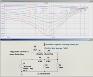
You can tweak the notch frequency to your taste by varying C1 and C2. However, if these caps get much bigger, there will be more treble droop at the high frequency end of the graph (due to the smaller capacitive reactance interacting with the output resistance of the preceding stage, which I set to 32k based on ECL82 datasheet parameter values.)
Having grown up teaching myself about Bode plots and Nyquist stability criteria and the golden rule that you never try to make the open loop gain and the closed loop gain of an amplifier converge at a closing rate of more than 6 dB/octave, I was rather shocked that this actually worked. On taking a closer look the key is, once again, the very small amount of negative feedback that's used - usually no more than 6 dB.
-Gnobuddy
My private guess was exactly that, 3 to 6 dB....you can only get 3 or 6dB before it starts to turn ugly...
You might actually gain about as much by bootstrapping the triode's anode load, raising the voltage gain to nearly the valve's mu.
But bootstrapping requires one more active device, either cathode follower or source follower - and if you're using one more active device, you'd gain far more by adding one more cascaded gain stage.
How about a passive notch filter with low insertion loss? The one I drew up and simulated in LTSpice has only about 3 dB - 6 dB insertion loss except around the notch frequency, where you can dial in quite a deep dip if so desired (image attached.)At present with no tone stack it sounds very middly
Note that R1+R3 is one single 1 Meg linear pot (LTSpice doesn't include potentiometer symbols or models, so I make my own with two resistors.)
Also, Vout should not be loaded, so it should go direct (possibly through a "grid stopper" resistor in series) to the control grid of the next valve. That control grid gets its ground reference through R3 + R4, and should not have a separate grid bias resistor of its own, otherwise Vout will be loaded and the frequency response will be adversely affected.
You can tweak the notch frequency to your taste by varying C1 and C2. However, if these caps get much bigger, there will be more treble droop at the high frequency end of the graph (due to the smaller capacitive reactance interacting with the output resistance of the preceding stage, which I set to 32k based on ECL82 datasheet parameter values.)
The "presence" control used in some guitar amps is a sort of tonestack in the feedback loop - usually a lowpass filter response in the feedback signal, which has the effect of making the amplifier's own frequency response into a shelving high-pass filter.I need to think about this. I wonder if I can include some sort of tonestack in a feedback loop.
Having grown up teaching myself about Bode plots and Nyquist stability criteria and the golden rule that you never try to make the open loop gain and the closed loop gain of an amplifier converge at a closing rate of more than 6 dB/octave, I was rather shocked that this actually worked. On taking a closer look the key is, once again, the very small amount of negative feedback that's used - usually no more than 6 dB.
That it does!Working with just two valve stages certainly limits your options
-Gnobuddy
Attachments
Looks like we are thinking along the same lines.
I will try a twin T notch right on the input. The Triode should have fairly high input impedance. You can mess with the notch (i.e. a "middle" control) with R10 on my attached circuit.
The amp has hum and the pentode current is more than the transformer would like, so I plan to raise the cathode resistor. I'm also going to raise the triode load from 120k to 180k to get a bit more signal.
Finally I will tweak the triode cathode circuit to include a low impedance feedback point - and play with this light positive feedback idea some more. That might be where the overdrive emulation gets put in, because there's no hope of getting valve crunch out of this single valve arrangement. I'm still avoiding adding transistors or op-amps so I can kinda say it's a one valve circuit..

Pete
I will try a twin T notch right on the input. The Triode should have fairly high input impedance. You can mess with the notch (i.e. a "middle" control) with R10 on my attached circuit.
The amp has hum and the pentode current is more than the transformer would like, so I plan to raise the cathode resistor. I'm also going to raise the triode load from 120k to 180k to get a bit more signal.
Finally I will tweak the triode cathode circuit to include a low impedance feedback point - and play with this light positive feedback idea some more. That might be where the overdrive emulation gets put in, because there's no hope of getting valve crunch out of this single valve arrangement. I'm still avoiding adding transistors or op-amps so I can kinda say it's a one valve circuit..
Pete
I don't think that will work.I will try a twin T notch right on the input.
That 1 meg pot can have a source impedance of up to 250k (when set to mid-point) even if the guitar was a pure voltage source. In practice, the guitar will have another 10k - 100k source impedance of its own, so the source impedance at the wiper of the pot is likely to be as high as 300 kilo ohms at some settings.
I think that enormous source impedance will mess up the intended frequency response of the notch filter. I don't have time to run it through LTSpice today, unfortunately.
The high resistive source impedance will also generate a lot of thermal noise right at the input of your amp. Normally this would translate to hiss at the speaker, but this may not be a problem in this particular case, since the amp has very little voltage gain, and output power is low, so you may not be able to hear much hiss.
Are there any loopholes in your "No semiconductors, only 1 valve in the amp" rule? What if there was a MOSFET inserted into a little die-cast metal box in the middle of the guitar cable, for instance?
-Gnobuddy
Yes, you are bang on the money
You know that feeling when you put in a circuit and think "I wonder why no-one else does it this way, perhaps I've invented something brilliant" - well as soon as I put the scope on it I realised it was a fail. The output impedance (into the triode) will be fine. But the twin T really does need a low impedance drive. The notch comes from phase cancellation I think, and I guess all that energy has to come from somewhere. I did consider reworking it as a higher impedance version but I decided that was not a good path to follow.
So, the twin T came out again, and I remeasured all the voltages, and here we are.

I have come to the predictable conclusions:
Yes you can make a strictly one valve guitar amp, but it won't have enough gain to sound good. You essentially have half an amp.
Yes you can add a little extra gain with positive feedback but the results are not worth the effort and the risks.
If you want a tone stack then you do need a two part amp, with a pre-amp and a driver/output. Just like Mr Fender decided in 1947....
I could put a 12AX7 on the front of this design - but the tiny 10w transformer wont support any more load. So in this case I will declare this to be a "Hybrid one valve guitar amp" and I am going searching my leftover stuff for a FET.
Meanwhile I might use this as an experiment platform. Perhaps I will reduce the pentode current to see how that changes the clipped sound, though I suspect it will reduce the gain even further. At the moment the output clipping is rather harsh on the oscilloscope, hence my usual trick of diodes in the feedback to create a rounder sounding clip.
Watch this space
Pete
You know that feeling when you put in a circuit and think "I wonder why no-one else does it this way, perhaps I've invented something brilliant" - well as soon as I put the scope on it I realised it was a fail. The output impedance (into the triode) will be fine. But the twin T really does need a low impedance drive. The notch comes from phase cancellation I think, and I guess all that energy has to come from somewhere. I did consider reworking it as a higher impedance version but I decided that was not a good path to follow.
So, the twin T came out again, and I remeasured all the voltages, and here we are.
I have come to the predictable conclusions:
Yes you can make a strictly one valve guitar amp, but it won't have enough gain to sound good. You essentially have half an amp.
Yes you can add a little extra gain with positive feedback but the results are not worth the effort and the risks.
If you want a tone stack then you do need a two part amp, with a pre-amp and a driver/output. Just like Mr Fender decided in 1947....
I could put a 12AX7 on the front of this design - but the tiny 10w transformer wont support any more load. So in this case I will declare this to be a "Hybrid one valve guitar amp" and I am going searching my leftover stuff for a FET.
Meanwhile I might use this as an experiment platform. Perhaps I will reduce the pentode current to see how that changes the clipped sound, though I suspect it will reduce the gain even further. At the moment the output clipping is rather harsh on the oscilloscope, hence my usual trick of diodes in the feedback to create a rounder sounding clip.
Watch this space
Pete
Last edited:
As you will no doubt have gathered, my theoretical knowledge of valve circuit design is limited, so I designed and built my little ECL82 amp as a basis for learning and experimentation.
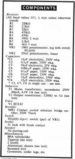
I've attached an old Wireless World magazine schematic for an ECL82 record player amplifier which incorporates tone control in the feedback loop.
I haven't tried this tone control arrangement and would very much value an expert opinion as to what its efficacy might be, e.g. its effect on tone and gain.
Thanks in anticipation.
Attachments
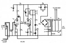
That looks like half a Baxandall tone circuit. They are often put in feedback around a single valve, transistor or op-amp. I've never seen it used round a whole amp before, but it should work. It is the treble control part if I have read the circuit correctly.
I put my FET front end in this mini amp this evening and - yes now there is enough gain and drive to put a tone stack in as well. It also drives the amp into clipping from a guitar.
I will stop my little project for a few days while I consider the next move. Something sounds a bit rough when you play guitar through it quietly. I can't see any oscillation on my scope, which goes to 100MHz. I want to chase that down before I go much further with the circuit.
It's a shame one valve won't quite do the job, but I will bend my rule and keep the FET there and call it a hybrid practice amp.
I have an 8 inch Fender speaker, now I need to get woodwork and metalwork to finish it off.
- Status
- This old topic is closed. If you want to reopen this topic, contact a moderator using the "Report Post" button.
- Home
- Live Sound
- Instruments and Amps
- Newbie: Hi there and a ECL86 question