I thought the cathode boils off electrons at a constant rate. Seems I was wrong.....
The heat just loosens the electrons. Why do they leave? Plate or screen voltage sucks them. Why don't they all leave at once? In normal operation the G1 voltage holds them back. There is an electron cloud, a virtual cathode, between K and G1. The electrons still in the oxide see this negative cloud and have no urge to leave the cathode.
The idea of higher V and lower I is pervasive in old tubes and particularly radio power tubes. Cathode stuff is expensive. With some qualification, plate voltage can be quite high. For a given Power (V*I), hi-V lo-I is a cheaper tube.
Fender Deluxe AA763 seems to exceed the highest numbers I know for 6V6.
Hi
6V6 was used as a vertical deflection amp in old TVs where it had to withstand 1,200V pulses, so it's a pretty tough tube. 470V in a Deluxe is no problem. Flyback peak + DC never exceeds 800V considering how much the supply sags under load.
Even though the latest manual says it is design-maximum values, the sheet refers to variants up to GTA but still lists the design-centre values for the original metal version of the tube. Shame on RCA. No wonder even experienced guys are confused?
PRR: luv your posts. I can't believe I know something you don't but I did learn it from someone else")
6V6 was used as a vertical deflection amp in old TVs where it had to withstand 1,200V pulses, so it's a pretty tough tube. 470V in a Deluxe is no problem. Flyback peak + DC never exceeds 800V considering how much the supply sags under load.
Even though the latest manual says it is design-maximum values, the sheet refers to variants up to GTA but still lists the design-centre values for the original metal version of the tube. Shame on RCA. No wonder even experienced guys are confused?
PRR: luv your posts. I can't believe I know something you don't but I did learn it from someone else
The 1967 sheet I linked says 350V design max. The design center rating for all older 6V6 is 315V. (Suggesting that center allows 10% for field variations.)
The HIGH-voltage Fenders come in the late 1960s, when 99% of tubes were made in about 3 plants. Leo may have had a gentleman's understanding that all the tubes he was likely to get, from whatever factory (all the brands horse-traded) would be made of 400V stuff, and he was not concerned about users using cheap replacements from odd sources.
There is no compelling reason to re-rate a tube if materials change. There is commercial reason to NOT re-rate, if it encourages sales of a similar tube sold at higher price. The 6V6 numbers are based on the 6F6 which it tended to replace, re-stated later as design-max instead of design-center (putting more onus on the OEM).
"Inductive kick" is a non-issue for symmetrical waves. Time above B+ same as time below B+... it averages out. (H-sweep waveforms are different.)
The "300V rating on most small tubes seems to be pure inertia. Small tubes rarely need more; when more is needed, usually a power tube is what is wanted. McIntosh treated 12AX7 to over 400V and it does not seem to be a problem.
The 300V numbers also come from standard radio practice. You had 450V e-caps. A vacuum rectifier. And then usually a 100V field-coil for more filtering. Taking 455V peak from PT, 55V drop in rectifier, 100V drop in field, is 300V. The older RF/IF tubes were usually worked from a 250V rail, a nice drop from 270V-320V at the Power tube. It all adds up, for the day and time. There's no benefit in amplifying sub-Volt RF/IF signals with high B+; even 250V is generous but it did increase the dynamic plate impedance for more gain and selectivity in IF tanks. But good radios were also made to work on 90V.
Last edited:
Thanks, I never really thought the cathode end of things through before.The heat just loosens the electrons. <snip>
The testbed is definitely not an ideal setup. I dont have much tube experience, and noticed that a lot of the old organ and console amps ran the screen within a few tens of volts of the plate. Reading RDH4 I realized that I dont understand the effect of screen voltage in a proper sense, so I used the smps so I could control the screen independent of b+, instead of it simply being a fraction of it, hoping to see the effect it has. Same with the bias voltage, it can be held constant, regardless of what b+ does. (Again, I'm assuming that a rectified bias source will sag when b+ does) I'm a serious case of not realizing how little I know. Probably just enough to make something work, without actually understanding why it works.
Cory
Cory
The screen sort of isolated the plate from the grid and cathode. Rather than the plate pulling the electrons to it the screen sets up an electric field that pulls the electrons from the cathode. In early amps they did not thing people will grossly distort the signal and turn the volume down when it does. For guitar amplification we do keep it turned up causing the plate voltage to dip low. When the plate is at a lower voltage it does not collect all the electrons that whizzed by the screen and the screen collects them as it is at a higher potential. This causes the screen current to go up at a high rate as shown on the graphs. We try to limit this by putting resistors in series with the screens. The increased current causes a voltage drop across the resistors and the screen voltage is reduced some, hopefully attracting less electrons and reducing screen temperature. Just a quickie explanation, others here are better at it.
The testbed is definitely not an ideal setup.
Your test bed looks better than my last few prototypes! I just lay everything on a wooden board and solder point to point until I like it.
Screen voltage has more of an impact on a pentode’s operating point than b+. A lower screen reduces gain and output power. That’s why good data sheets have a few sets of curves for different screen voltages. In fact IIRC you can estimate your negative bias by dividing the screen voltage by mu. If you regulate the screens you have to regulate the bias (and vice versa) but b+ can bounce around a bit.
Now that I have the power section operational, I need to add in a preamp. The chassis has several 12a?7 and several 6au6 sockets, so there are endless possibilities there. For starters, I'll build the preamp and tone stack on a "standard" fender tmb design (suggestions would be very appreciated), and see how it sounds.
(suggestions would be very appreciated)
Head over to RobRobinette's site and have a look at the mini/micro amps for starters.
Champs have their own charm at one end of the trad-amp spectrum (1 valve, two knobs); JCM800 at the other (3 valves, full TMB and high gain).
Supro have a different tone stack set up.
Be careful, it's a slipperly slope!
Yes, during flyback, when being cut-off, with no plate current, and just for a few microseconds...6V6 was used as a vertical deflection amp in old TVs where it had to withstand 1,200V pulses...
Best regards!
Hi
Anyone who thinks that guitar amps use the tubes out of spec do not know about tubes or tube safety rules, so in this regard, nearly ALL musical instrument amps run the tubes within ratings. They have to, or there would be a lot of damaged OTs.
The only abuse you see occasionally is screen voltages being exceeded, as in the Marshall 2-375W amps from the 1980s. High screen-stops save those tubes but otherwise all within spec.
Data sheets are filled with hi-fi applications that in general DO NOT reflect the capability of the tube.
I respectfully disagree. Leo Fender ran 6V6s in amps like the Deluxe at 100v over the spec for decades. Clearly tubes will withstand conditions far in excess of the spec sheets.
Very true Enzo.
I'm constantly having to replace cathode resistors in AC30's to bring them down from *way over max plate dissipation.
And they are by no means the only offenders.
That's guitar amps.
...noticed that a lot of the old organ and console amps ran the screen within a few tens of volts of the plate....
SO??
We do not use True Tetrodes! For anything! Rip those pages out of your books!
A Pentode (includes "Beam Tetrodes" which are truly pentodes) can swing the plate WAY below Vg2, to maybe 20% of Vg2, without any funny effects.
The relative potentials of Plate and G2 are NOT directly meaningful.
Vg2 directly limits the Maximum Plate Current. Look at the attached 7027 curves.
Vg2 = 150V -- 75mA
Vg2 = 300V -- 210mA
Vg2 = 450V -- 385mA
Output power is voltage times current. If you have big tubes and wish to run a low main supply voltage, you normally raise Vg2 as high as is convenient (or until something melts).
You "could" run a 300V plate supply and a 450V G2 supply... but that would be inconvenient.
You sure can run a 600V plate supply and a 300V G2 supply. See 6550 8417 KT88 100W suggestions. But G2 current varies a lot, and it is normally inconvenient to derive a well-regulated G2 supply from a much higher plate supply. (Solid-state rectifiers made this more convenient.)
In a clean-sheet amp-only design, it could be "optimum" to design a low Mug2 tube to get large current at low Vg2 and low Vg1 bias and drive. But that moves the inconvenience to the power supply's Vg2 supply. In RF work where high impedance loads are practical, you do see 700V on plates, 200V on G2, and a separate Vg2 rectifier/supply.
In Audio, we dislike really high impedance loads (cuts bandwidth). And also separate G2 supplies. There is a class of Audio Power tubes which are designed to work well with Vg2 near or slightly less than plate supply. This includes all our 6V6 6L6 ELx4 the KTs and others.
So yes: Vg2 near (even above) plate voltage is a perfectly respectable thing to do.
Attachments
Wow! I sincerely appreciate the knowledge shared on this forum.
PRR
Thanks for that! It's like the clouds parted and the sun was let in. I appreciate your time and examples. Screens make more sense now.
My test bed oscillator is doing great in the kilohertz region... one day it will just amplify! Interesting how screen current rises when it oscillates.
I even took it back to cathode bias, and screen supply from b+ no smps just resistors, as I thought it was switching noise.
Going to take a few days to get some study time in before I heat the amp back up.
Thanks for all the help. At some point I'll have this thing going, and be able to adjust it to textbook values, and see how it sounds.
I'll start with a simple volume only, then single tone control, and if I can get that to work without it wanting to transmit low frequency morse code, I'll go for a TMB and master volume.
Cory
Last edited:
Very good point, as this is just the most advanteous propriety of screen grid valves!A pentode (includes "Beam Tetrodes" which are truly pentodes) can swing the plate WAY below Vg2, to maybe 20% of Vg2, without any funny effects.
We could also add 807, LS-50, GU-50, EL152, e.g.You sure can run a 600V plate supply and a 300V G2 supply. See 6550 8417 KT88 100W suggestions.
Best regards!
me> ...swing the plate WAY below Vg2
KP> ... this is just the most advanteous propriety of screen grid valves!
Watch your language.
"Screen grid valves" includes True Tetrodes. Which go goofy when Vg2<Va.
The "propriety" that I think you mean comes from G3, Suppressor Grid (or side-electrodes).(*) This discourages splash-back electrons from Plate going to Screen, the "problem" with True Tetrodes.
(*) The electrons do not care if the potential minimum between G2 and Plate is induced by a loose "grid" or by side-plates. But they look very different on the patent drawing, why RCA _never_ said the P-word around the 6L6. The two techniques have other tendencies, but there are many tricks and "same" tubes have been built both ways.
After several hours of reading (mostly the Radiotron Designers Handbook) I realized that I needed to look at my power supply. Sure enough, I hadn't decoupled my preamp from my screen supply. I added a 27k resistor, and a 10uf cap and she plays a lot nicer now.
I finally broke out the oscilloscope, and also found that the coupling capacitors between the phase inverter and the 6v6's weren't letting much signal past. I guess I should verify all the components that I reuse, sure would have saved some head scratching.
Now that I know the transformers and everything will work, I just need to cleanup the grounding scheme to quiet down a little hum, and I'll be ready to experiment with a tone stack. After that, I'll see if I can add back the smps and bias supply, and see if the operating listed in the manual sounds different (better or worse being too subjective). Then I can start to answer the original question, with some firsthand experience.
I still cant believe the knowledge gathered and shared here. It allows a "dumb ole lineman" as we call ourselves, to learn how and where to look for info to make decisions instead of just guesses!
Cory
Fender reissued some of their 1960's amps, and kept the original power transformer specs for authenticity in some cases. Meantime, the AC line voltage in North America has climbed considerably since 1960.The HIGH-voltage Fenders come in the late 1960s, when 99% of tubes were made in about 3 plants. Leo may have had a gentleman's understanding that all the tubes he was likely to get, from whatever factory (all the brands horse-traded) would be made of 400V stuff...
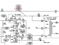
Combine the too-high 1960's voltages with original-spec transformers and higher contemporary line voltage, and the results are ridiculous. The Fender schematic for my '65 Princeton Reverb reissue shows 440 volts DC on the 6V6 anodes.
The 6V6 screens are fed from node "Z" on the power supply. The power supply schematic shows 425 volts DC at point "Z".
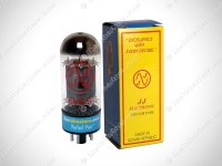
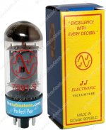
The result is that most of these amps end up using JJ 6V6S output valves, pretty much the only current-production "6V6" that are beefy enough to tolerate the abusive screen voltage. Unfortunately, the JJ 6V6S doesn't sound much like a real 6V6 tube, tending to be too clean and sterile sounding.
If you look at the attached images, it would seem the JJ "6V6S" is identical in internal construction to their JJ 7591. Original Tung Sol datasheets show the two valves to have been very different (with quite different distortion specs), but who's to argue about it today? JJ can slap any label on any tube they want (probably some random Russian tube that had adequate ratings), as long as the pinout is correct.
-Gnobuddy
Attachments
- Status
- This old topic is closed. If you want to reopen this topic, contact a moderator using the "Report Post" button.
- Home
- Live Sound
- Instruments and Amps
- Tube Guitar Amp - Running Output Tubes in Spec?