Hi
I have a pretty old radio.
A Bang & Olufsen Grand Prix 43K.
But it is a mess, wires are cracking, capacitors melting or leaking, the works.
I can't find the schematics to do a proper rebuild, and I don't really need a long wave radio anyway.
So what I want to do is build a guitar amp out of the parts.
My problem is, I can't for the life of me figure out how to use the UBL1 power tubes. They are dual diode, single pentode.
And i can't figure out if any of the other tubes can be used as a preamp.
So, I am looking for someone to design a circuit using the UBL1 tubes, and maybe some of the others if needed. It doesn't have to be fancy, with a tone stack etc. Just simple.
I just need the amplifier circuit, I should be able to do the power supply by myself.
I'm willing to pay up front for the service.
/R
I would not bother with the tubes from the radio. I could not find the exact radio but usually a manufacturer does not try to reinvent the wheel when making many products. This one shows the same output tube. The UBL21 is the replacement tube. https://www.vintageshifi.com/repert...ge.php?pdf=Bang-Olufsen-MINI-47-Schematic.pdf
https://frank.pocnet.net/sheets/046/u/UBL1.pdf
Now the problem you have is you do not have a power transformer and the radio is directly off the line, not good for something you are attached to through your strings. The best I could suggest is get another output tube that can use the 3.5k ohm output transformer. Measure the speaker impedance to get the ratio if you use other than the stock speaker. Then use a 'standard' tube type rather than use the tube set in the radio. Not what you probably want to hear but more practical.
Got oddball tubes!So I've got a question: The filament of UBL1 is 55V@0.1A, and the plate + screen voltages are low, under 200V.
I'm thinking about using one 230V:115V power transformer for everything: First, getting the B+ of about 145V with a bridge (although it seems a bit low) and then putting a VR90 tube (I've got one nice ST) and wiring the heater of UBL1 in series with some preamp tubes to get 90V total. There are several choises for 0.1A heaters tubes, but the cheap tubes are mostly noval or 7-pin type which looks not good together with UBL1. There's a UF9 pentode that looks proper, but it's a bit expensive ($13.90 at Antique Electronics) and the heater is 12.6V so I will need three of them. I may wire them as triodes and it'll be fine but still a bit too Xpensive.
Is there a problem with this setup - first B+, then 0.1A heaters from the same secondary?
And if that's okay, what other tubes may fit the preamp
https://frank.pocnet.net/sheets/046/u/UBL1.pdf
Now the problem you have is you do not have a power transformer and the radio is directly off the line, not good for something you are attached to through your strings. The best I could suggest is get another output tube that can use the 3.5k ohm output transformer. Measure the speaker impedance to get the ratio if you use other than the stock speaker. Then use a 'standard' tube type rather than use the tube set in the radio. Not what you probably want to hear but more practical.
One question first: does the radio have a power transformer?
U- tubes (100mA series heater) were often operated directly from the mains.
The UBL1 has a 55V heater. Before you continu make sure you have a power transformer with that voltage, or the combined voltage of the series of U-type tubes.
U- tubes (100mA series heater) were often operated directly from the mains.
The UBL1 has a 55V heater. Before you continu make sure you have a power transformer with that voltage, or the combined voltage of the series of U-type tubes.
The name of the radio up above is a link to the model.
There is a power transformer in the radio. It's running on 240v here in europe, and there's a huge plug on the back of the radio i can use if I need to change the input voltage. Very versatile system I must say.
I'll snap some photos and upload, so hang on.
There is a power transformer in the radio. It's running on 240v here in europe, and there's a huge plug on the back of the radio i can use if I need to change the input voltage. Very versatile system I must say.
I'll snap some photos and upload, so hang on.
Last edited:
The 43K has two UBL1 tubes presumably used for its power amplifier. It is probable that these are already configured as a push-pull power amp in a reasonable manner. In other words, you might be able to use the output stage as is. Trace out the schematic and see what it's doing. You may have to strap the anodes of the diodes to ground or the cathodes if they aren't already.Hi
I have a pretty old radio.
A Bang & Olufsen Grand Prix 43K....
So what I want to do is build a guitar amp out of the parts.
My problem is, I can't for the life of me figure out how to use the UBL1 power tubes. They are dual diode, single pentode.
And i can't figure out if any of the other tubes can be used as a preamp.
/R
You can use one of the UCH4 (heptode/triode) tubes as a phase inverter. Refer to page 159 in this data sheet: http://www.mif.pg.gda.pl/homepages/frank/sheets/046/u/UCH4.pdf.
The UF9 will serve well as an audio preamp or intermediate gain stage.
The extra UCH4 can be employed as a gain stage with some creative thinking or abandoned.
I'd ditch the UY1 rectifier, install (a presumably missing power transformer) and use a more common full-wave rectifier.
If you want to keep the UM4 as a VU meter of sorts, that'd be interersting or you could ignore it.
The main challenge to this sort of conversion is that the tube complement for this radio is intended for a series heater arrangement across a 220 volt a.c. supply (probably with a dropping resistor). Using these will require some thought to get the heaters working reasonably.
Stph
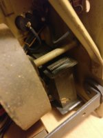
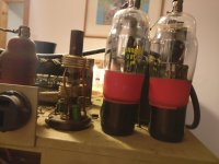
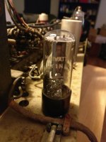
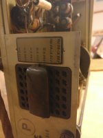
I've attached some pictures. One is showing the powertubes... and what is that thing next to it? it was covered in an aluminium tube. One is showing the big plug on the back side that controls what input voltage it accepts. One is showing the rectifier tube, just because. And one is showing the input transformer.
Don't know which order they are in. Very archaic messageboard I must say")
I have downloaded LTspice and will try to draw out the circuit. I just realised I have A LOT to learn still. Thank you so much for your help so far, I'll probably have more questions soon.
This is quite a step up from a 12AX7 + EL84 amp.
Don't know which order they are in. Very archaic messageboard I must say
The 43K has two UBL1 tubes presumably used for its power amplifier. <snip>
I have downloaded LTspice and will try to draw out the circuit. I just realised I have A LOT to learn still. Thank you so much for your help so far, I'll probably have more questions soon.
This is quite a step up from a 12AX7 + EL84 amp.
Attachments
Oops, thought it was single ended. https://www.vintageshifi.com/repert...-Olufsen-MASTER-DE-LUXE-41-Service-Manual.pdf
And using the superseding replacement tube of the UBL1. https://www.vintageshifi.com/repert...-Olufsen-GrandPrix-506-K-1950-D-Schematic.pdf
And using the superseding replacement tube of the UBL1. https://www.vintageshifi.com/repert...-Olufsen-GrandPrix-506-K-1950-D-Schematic.pdf
There is a power transformer in the radio....
This is NOT a safe candidate for a guitar amp.
It is "Hot Chassis". The audio common is connected to the power line without transformer *isolation*.
Yes, it has a huge choice of line voltages. It does this with series/parallel combinations of heaters and a small autotransformer (not isolating) for the higher AC lines.
Note in particular: it has options for DC power lines. You can't change DC voltage with a transformer, but the B+ can be fed straight DC, from 110V to 150V, with an added resistor or at reduced maximum output. (DC power lines were somewhat common in industrial districts into the 1950s.)
Hot chassis is safe *for radio*. Radio waves in, sound waves out, the user never touches the circuit. But a guitar player holds one side of the circuit in his hands while touching grounded objects.
Last edited:
The link says it is an AC/DC set, so it has no power transformer. This is to be expected for a set using 100mA heater valves. It is therefore not safe for use for audio, unless completely rebuilt in the power supply area. Much easier to start from scratch or with a kit.Rasped said:There is a power transformer in the radio.
This is NOT a safe candidate for a guitar amp. <snip>
Oh bugger.
I will built it safe for the ground up then. Thanks for the heads up. For future reference, how do I spot those radios? I have some other radios that are from the mid 50s, will they have the same problem?
Last edited:
Look for valves with names starting with U or 10. That indicates 100mA heater, which almost always means no mains transformer. Rarer is 150mA heater chain, indicated by valves starting with H or 12. AC-only sets with a mains transformer will usually have valves starting with E or 6.
Look for a mains transformer. However, a few sets had a transformer for the heaters and still had direct connection for the main supply rail so the presence of a transformer is not conclusive. The absence of a transformer is conclusive.
Google the set, and read what you find. If it says AC/DC then it will have a live chassis.
Consider the age and size of the set. Generally, the smaller and later the set the more likely it is to be live chassis.
Don't get too dissapointed! Get a 230/230 V isolation transformer of appropriate power (look at the back wall for the radio's power consumption!), remove anything from the chassis that doesn't belong to the AF amplifier (i.e. leave just the last UCH4 and both UBL1's with their periphery), replace the one way UY1 rectifier by a silicon bridge, replace the mains filter capacitor, add another gain stage, using the IF or converter tube, add a tone control between this stage and the AF amplifier, leave the series heater chain, but feed it from the isolation trannie's secondary, and replace the ballast resistor by an appropriate capacitor to reduce heat and power consumption.
Remember that you've got a PP output stage after all!
Best regards!
Remember that you've got a PP output stage after all!
Best regards!
Guys
I am genuinely scared by what you're saying.
I have to admit that I have converted 3 newer radios (from the 50s)... and played them with my guitar. Obviously not fried yet, but I will stop playing them for sure until I have made absolutely sure they are safe.
How was it even legal to construct death machines like this?
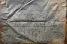
Am I correct when I think this schematic shows a safe circuit?
Powersupply is top right corner
On closer inspection... probably not. Looks like the filament is powered directly on 220v as well... damnit.
I am genuinely scared by what you're saying.
I have to admit that I have converted 3 newer radios (from the 50s)... and played them with my guitar. Obviously not fried yet, but I will stop playing them for sure until I have made absolutely sure they are safe.
How was it even legal to construct death machines like this?
Am I correct when I think this schematic shows a safe circuit?
Powersupply is top right corner
An externally hosted image should be here but it was not working when we last tested it.
On closer inspection... probably not. Looks like the filament is powered directly on 220v as well... damnit.
These radios were perfectly safe when used as radios. Many TVs in Europe used a similar system. People repairing them or fiddling with them would be aware of the dangers and act accordingly.
I will be careful now.
Rasped,
would you please upload your picture here? I absolutely don't want to create a Microstuff account just for having a look at it.
Best regards!
There you go. Sorry about that.
Attachments
Yes, I own that one as well. Linnet Laursen 5812.
Capella FM-AM 5812 Radio Linnet & Laursen LL A/S; Kobenhavn,
Twin 8 inch speakers. Has a nice clean sound. I modded it to have a bit more gain, so it is a bit of crunch when cranked and playing a humbucker guitar through it. Well... not playing it again before it has been modded with an isolation transformer already figured out where to mount that. Do you think a 50w transformer is enough?
Capella FM-AM 5812 Radio Linnet & Laursen LL A/S; Kobenhavn,
Twin 8 inch speakers. Has a nice clean sound. I modded it to have a bit more gain, so it is a bit of crunch when cranked and playing a humbucker guitar through it. Well... not playing it again before it has been modded with an isolation transformer
already figured out where to mount that. Do you think a 50w transformer is enough?- Status
- This old topic is closed. If you want to reopen this topic, contact a moderator using the "Report Post" button.
- Home
- Live Sound
- Instruments and Amps
- Repurpose of old radio