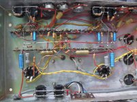
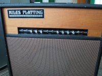
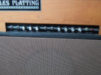
First timer, or at least first time for some years. I have recently acquired a MILES PLATTING (Wilsic) dual input 30w per channel valve guitar amp and although it "works" it does have a constant noise which increases when I increase the volume.
Is this something common to old valve amps or is there an issue which can be fixed?
All hand wired. Changed the GZ valve to a mallard as old one was failing.
How do I attach a pic??
ammers2
Is this something common to old valve amps or is there an issue which can be fixed?
All hand wired. Changed the GZ valve to a mallard as old one was failing.
How do I attach a pic??
ammers2
Attachments
Last edited:
Hi Jon thanks for quick reply and your interest.
First let me just say I have little to no experience with electronic equipment so please be patient with me.
The noise is a low tone hum, not present when vol is at zero but increases as volume is turned up. The tone stays the same but increases in volume. It occurs whichever input I use.
Do you suggest trying new ECC83's? and could you point out what a 100k anode is and looks like?? (I did warn you)
Thanks
Steve
Attachments
The problem is probably one or more of the power supply filter caps. You may want to replace them all if they are decades old. A quick test used by service people is to take a similar capacitor and touch it across the supply caps, one by one. !!Don't get it backwards, observe polarity!! This will cause an arc (zap!) at first but once the test cap is charged and connected, it will ~fix the noise when you find a bad cap. Don't forget to discharge (short) (zap!) the cap after or you might get bitten handling it.
Note that the upper can (in the photos) is two capacitors, test both separately.
Note that the upper can (in the photos) is two capacitors, test both separately.
Last edited:
Also note that this amp has a 3 wire power cord so it does not have a "ground switch". If by chance the ground pin has been cut off or your power does not have a safety ground, you will have to find a way to ground the amp. A ground switch connects a ~0.01uF cap from the chassis to either side of the AC line, so when you find neutral, the buzz goes away. But it's better to use a proper safety ground (green wire) if available.
Last edited:
Helpful images and details of a Wilsic amp are to be found on this site:
Repair of a Wilsic 50 Watt Guitar Amp
Is this the same as yours?
Repair of a Wilsic 50 Watt Guitar Amp
Is this the same as yours?
Thanks for all the info guys. I will read through it all in more detail in next day or two and hopefully report back. Galu thanks for the heads up o the website - again I will need to look in more detail but it looks very similar.
I will probably have a go at replacing the 3 (4) large caps - any suggestions as to replacement makes?
ammers2
I will probably have a go at replacing the 3 (4) large caps - any suggestions as to replacement makes?
ammers2
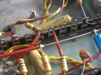
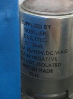
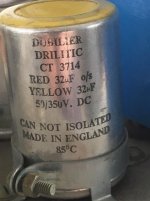
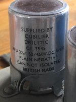
In your photo, the top capacitor is a dual can while the other two are single can. If you can read the capacitance (uF) and voltage (V) values written on each of the cans, we might locate suitable replacements for you.
The ECC83 valve nearest the two EL34 output valves will be the phase splitter. Have you tried swapping it for one of the other ECC83s?
The ECC83 valve nearest the two EL34 output valves will be the phase splitter. Have you tried swapping it for one of the other ECC83s?
Thanks Galu I will look at that next. In the meantime I have checked all the 100k anode resistors and all read around 102k - is that ok or too far out of tolerance?
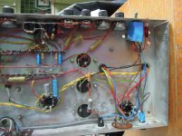
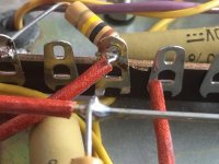
I have found (see pic) this resistor which has come desoldered - I'm not sure if I've done that with my own proddings but of course it needs resoldering. However not sure where it goes - choice of two tags on the rail one directly across from resistor has no solder residue/wear so i'm thinking it attaches to the tag on the left with the other parts??? see pic
big question - could this be causing the noise issue on it's own??
Now where's my soldering iron!
Attachments
Pics of capacitors Miles Platting amp
Hi all
edit on last post - I checked the resistors in situ, not desoldered even at one end so readings of course may be influenced by other parts?
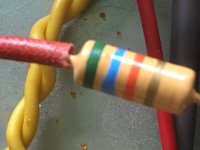
thanks for all your help on this. Pics show the 3 capacitors. The second one (middle of the 3 on the actual amp) is RED 32uf.
Suggestions for reasonable priced alternatives please?
Steve
(PICTURES TO FOLLOW)
Hi all
edit on last post - I checked the resistors in situ, not desoldered even at one end so readings of course may be influenced by other parts?
thanks for all your help on this. Pics show the 3 capacitors. The second one (middle of the 3 on the actual amp) is RED 32uf.
Suggestions for reasonable priced alternatives please?
Steve
(PICTURES TO FOLLOW)
The Green, Blue, Orange resistor certainly doesn't belong to the empty tag.
It appears to have been attached to the tag to the left where the Brown, Black, Yellow resistor is attached.
Some of those solder joints look very poor, having the minimum amount of solder, and they should now be re-soldered properly.
The unattached resistor will certainly cause an issue!
P.S. The 102k readings seem fine - concentrate on the other areas of concern.
I don't know where you are based, which influences which parts supplier to go to.
You could buy three dual 32uF 500V capacitors and just use two of them as single 32uF capacitors. Here's an example of what I mean:
Capacitor can 32uf+32uf 500v - ma cap - Modulus - UK Guitar Amp Parts and Kits
You could buy three dual 32uF 500V capacitors and just use two of them as single 32uF capacitors. Here's an example of what I mean:
Capacitor can 32uf+32uf 500v - ma cap - Modulus - UK Guitar Amp Parts and Kits
Here are some schematics which might help:
Index of /tubes/MilesPlatting/Schematics
Index of /tubes/MilesPlatting/Schematics
Very helpful Malcolm - thanks!
This is the one:
http://edgaraudio.se/tubes/MilesPlatting/Schematics/MilesPlatting-50.jpg
This is the one:
http://edgaraudio.se/tubes/MilesPlatting/Schematics/MilesPlatting-50.jpg
Now that we have the circuit diagram and are able to compare your first photo in post #1 with the 'Repair of a Wilsic 50 Watt' photo, please put a hold on the resoldering of that Green, Blue, Orange (56k) resistor!
The circuit may have been tampered with. Looks like the free end of the 56k should go straight across the tag strip then attach to the 16 ohm tap on the output transformer via a missing length of wire.
Removing the feedback loop like this may have been done to increase the gain but would also increase the hum.
I would value a second opinion on this before asking you to proceed further.
- Status
- This old topic is closed. If you want to reopen this topic, contact a moderator using the "Report Post" button.
- Home
- Live Sound
- Instruments and Amps
- 70's valve guitar amp needs TLC