HI Everyone,
I have a Warwick_Profet-3.3 Bass Amp with no sound.
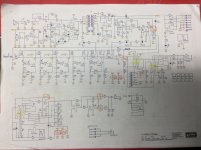
I've attached a schematic screen shot.
I have traced the signal through the preamp and into the main board,
I replaced an open resistor along the way and now I seem to be loosing it at LTV-824 area. Im not sure how this optocoupler works.
I have a signal at R120 before and after.
I have a signal at R121 before but not after. I think the signal should be present here too but not sure.
on the LTV824 I have no signal on the collector pins 6 +
8.
C58 is good and all neighbouring components are good.
I also have the +/- 15v present in this area.
Would this LTV 824 be faulty.
any help would be appreciated.
I have a Warwick_Profet-3.3 Bass Amp with no sound.
I've attached a schematic screen shot.
I have traced the signal through the preamp and into the main board,
I replaced an open resistor along the way and now I seem to be loosing it at LTV-824 area. Im not sure how this optocoupler works.
I have a signal at R120 before and after.
I have a signal at R121 before but not after. I think the signal should be present here too but not sure.
on the LTV824 I have no signal on the collector pins 6 +
8.
C58 is good and all neighbouring components are good.
I also have the +/- 15v present in this area.
Would this LTV 824 be faulty.
any help would be appreciated.
Attachments
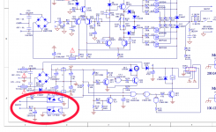
Those look to be part of the fan control circuit and the spkr relay circuit. Under normal conditions you should have a positive voltage on the collectors of the LDRs. Under fault conditions the collectors will be pulled towards ground. Once the input on the 1st U3 goes low the output will go high causing the next U3's output to go low and turning Q23 off and de-energizing the spkr relay.
Craig
Craig
Last edited:
U4 detects an output short, ie high current R118;R119
OE2 detects DC on the output, ie failed FETs
Both of these draw current from R122 and remove voltage on C56. preventing the relay activation.
RR2 detects heat and when it exceeds a point, activates Q21 which again removes voltage on C56, and disconnects the output.
R130 goes to CN2B which is another way that can shut down the amp.
Q23 could be open.
The relay could be damaged or oxidized.
C58 could be bad, but not if their is little or no AC voltage on it. It's job is to remove signal voltage (not DC).
You should have voltage on C56 and first side of R131. You should have very little voltage on the collector of Q23.
Last edited:
Many thanks for the replies.
Under normal conditions you should have a positive voltage on the collectors of the LDRs.
Voltage on the collectors of the LDRs is 0v (not good)
Once the input on the 1st U3 goes low the output will go high causing the next U3's output to go low and turning Q23 off and de-energizing the spkr relay.
Ok, this seems to be whats happening here.
OE2 detects DC on the output, ie failed FETs
Tested all 6 FETS and all test ok. Removed old solder cleaned and re-soldered.
Both of these draw current from R122 and remove voltage on C56. preventing the relay activation.
C56 has 12 v on it and 12v on the first side of R131.
R130 goes to CN2B which is another way that can shut down the amp.
R130 tests ok.
Q23 could be open.
Q23 tests good.
C58 could be bad, but not if their is little or no AC voltage on it. It's job is to remove signal voltage (not DC).
C58 Has no AC voltage on it. It tests ok.
You should have voltage on C56 and first side of R131.
C56 has 12 v on it and 12v on the first side of R131.
You should have very little voltage on the collector of Q23.
Collector of Q23 is 0.7v
The relay could be damaged or oxidized.
So I took the relay off the board and tested it on a 12v supply. I could hear it clicking.
I Cleaned the area and soldered it back in.
Powered up the amp again and heard the relay click. checked output on scope all there - Looking good. I think the relay may be sticking because I noticed it did not turn on again after I rebooted the amp however it did turn on after a little tap with a screwdriver. I think I will order a new relay.
so, I shouldn't have been tracing signal or looking for input signal after the LTV-824.. I should have been measuring voltages.
I checked the voltages now and see a positive voltage on the collectors of the LDRs.
I checked for my signal again and it is only present on pin 1 of the LTV-824. This must be normal under normal operating conditions.
Craig and Steve, Thanks very much for helping
Hi everyone,
I have this amp running again but there is something not right with the Preamp EQ section and I was hoping someone might help me on finding the fault..
When the pots are adjusted I’m hearing horrible noise and cracking noise in the signal. Ie. When the hi treble is turned it sounds like a record player playing a bad scratched record. It’s fine if all pots are set to default position (12 o’clock). It’s quiet then. Playing normal.
I changed out IC3 Opamp, but still there. Lubed all pots with Deoxide D5. It’s not dirty pot syndrome.. I reworked the entire preamp board fixing a load of dry joints. All electrolytic caps test good. Transistors are good. Resistors good. I notic that there is no line out signal either on the line out jack. I’m changing the relay in case it might be that but I don’t think so. I played in through thevreturn jack input and it’s perfect. The fault is on phones, Efects out, main out, tuner out, no line out yet.
Any thoughts would be greatly appreciated. Thanks in advance.
Paul
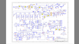
https://elektrotanya.com/cgi-bin/download2.cgi?fid=184068&file=warwick_profet-3.2_sch.pdf
I have this amp running again but there is something not right with the Preamp EQ section and I was hoping someone might help me on finding the fault..
When the pots are adjusted I’m hearing horrible noise and cracking noise in the signal. Ie. When the hi treble is turned it sounds like a record player playing a bad scratched record. It’s fine if all pots are set to default position (12 o’clock). It’s quiet then. Playing normal.
I changed out IC3 Opamp, but still there. Lubed all pots with Deoxide D5. It’s not dirty pot syndrome.. I reworked the entire preamp board fixing a load of dry joints. All electrolytic caps test good. Transistors are good. Resistors good. I notic that there is no line out signal either on the line out jack. I’m changing the relay in case it might be that but I don’t think so. I played in through thevreturn jack input and it’s perfect. The fault is on phones, Efects out, main out, tuner out, no line out yet.
Any thoughts would be greatly appreciated. Thanks in advance.
Paul
https://elektrotanya.com/cgi-bin/download2.cgi?fid=184068&file=warwick_profet-3.2_sch.pdf
Attachments
Thanks Craig, I checked the pots between HGND and the 3 terminals for each pot and there seems to be next to 0v present on the input gain, Comp rate and Contour grade pots.
5.3mV DC on all the EQ VR's.
38.0mV on the master pot..
when either the Bass, Low Mid, High Mid or Treble pots are adjusted away from 12 (centre) it basically sounds like your at the beach.lol with no input connected, input gain down, Master at 12
Ive changed all the electrolytic caps on the preamp board. The grounding is good. The resistors all test good.
I swopped out IC3A opamp with same and it made no difference.
I measured on the main speaker output with no speaker connected 173mV DC. this seems pretty high. The problem could also be on the main board too I suppose. Although I did check all the electrolytic caps there and they tested ok.
Thinking of changing the Master Volume opamp IC4 next. Im guessing now at this stage.
http://www.warwick.de/warwick/data/...Discontinued WW/Amps/Amphead/PROFET_32_33.pdf
Do you have any deoxit or rubbing alcohol? Try to get some Electronics cleaner inside the pots (openings near solder lugs is a good entry) and rotate the shafts to work it in to the internal wafer traces. Do this with power disconnected. Let it dry, test. May just be super cruddy pots.
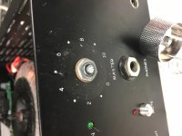
Yea, good idea,would be great if it was that �� I used deoxit D5 initially and before the last post. Spraying it in from pcb side. I can’t get the dam pot knobs off to get in at the shoulder of it from the front.
There is a small grub screw on each one. I remove it no problem but the chrom knob won’t budge. it is the tightest ever I’ve seen. I’ve tried vice grips on them Just can’t get any of them to budge. I’m afraid of breaking the pot too. I’ll try it again later. Blow them out with the air line and deoxit them again.
There is a small grub screw on each one. I remove it no problem but the chrom knob won’t budge. it is the tightest ever I’ve seen. I’ve tried vice grips on them Just can’t get any of them to budge. I’m afraid of breaking the pot too. I’ll try it again later. Blow them out with the air line and deoxit them again.
Well guys thanks for the help but I’ve never seen anything like this. I broke the master pot trying to get the knob off. I heated it a little with the quick hot air station and tried carefully prising it off with a flat head screwdriver. It prised off ok...broke at the base. I’ll have to look for a c250k to replace it and drill out the base of the old knob. I think these pots where not meant to be taken off the front display in this model.
Attachments
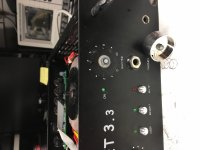
Unless someone glued the knob to the shaft, they are indeed designed to be removed. Aluminum shafts don't like to be bent much.
RV16AF-20-15S1-C250K-LA Alpha (Taiwan) | Mouser
RV16AF-20-15S1-C250K-LA Alpha (Taiwan) | Mouser
")
I’ve replaced all the electrolytic capacitors, replaced all the opp amps. I’ve tested all resisters/diodes/non polarised caps and reworked the complete opp amp board. I still have hum on the bass pot and the sound of the sea on the hi treble and noise on the middles when I turn the eq pots.
I’ve made a little signal tracer where I can listen in to the input (iPod) and follow it along the circuit. It’s clear all the way until it hits The other side of R19. I’ve marked noise where I can here the noise and good when it is clean.
The transistors all test good with there respective voltages.
If it is the pots at fault surely they all wouldn’t be faulty. And the problem there is I can’t remove the knobs because they are stuck for eternity...
Any help would be greatly appreciated
Attachments
- Status
- This old topic is closed. If you want to reopen this topic, contact a moderator using the "Report Post" button.
- Home
- Live Sound
- Instruments and Amps
- LTV-824 Optocoupler understanding