I have a Fender Pro Jr that was red-plating.
The bias voltage starts out at -10.5v just as it should, but then it begins to drop slowly. It keeps going down and I have seen it around -4v. This was with the tubes removed.
I have replaced almost every part in thebias circuit to no avail.
While the bias voltage drops the B+starts to rise? It is supposed to be around 350v, but I have it at 500v!
If I remove the ac coupling cap used to drive the bias voltage circuit, then the bias voltage is zero, and the B+ sits right at 350v like it should.
I am thinking thre must be a solder short somewhere, or a wrong part? It has been extensively repaired by the owner. At least it was attempted.
There is no way your B+ should be able to get to 500v. The power transformer is only 260vac red to red.
You are getting a false reading there. You probably have a bad ground connection somewhere around the rectifiers or first filter cap. This would also explain the drop in bias.
You are getting a false reading there. You probably have a bad ground connection somewhere around the rectifiers or first filter cap. This would also explain the drop in bias.
OK, time to do something else for a bit. But here is what I found out today. It is still a mystery, but I am not crazy.
I put a dmm on the hv secondary and set it to AC volts. When I powered it up it was rock solid at 250vac.
I put a second DMM on the B+, and while I watched the AC hv stay constant I could see the B+ steadily rise.
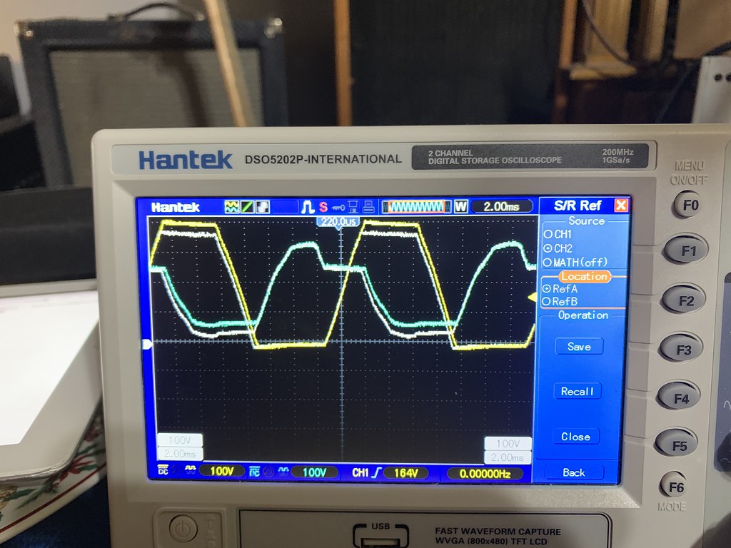
I put a scope probe referenced to chassis ground on the point where the hv secondary connects to the diodes. One channel on each of the leads. I could get a similar result by adding a DC offset into the output of the transformer output in my pspice simulation. I captured it after a few seconds and then waited a few more seconds and halted the scope and took a picture. You can see the earlier voltage levels on screen in white.
 IMG_2806 by Dennis Kelley, on Flickr
The scope trace in yellow was the one connected to the same side as the bias circuit coupling cap.
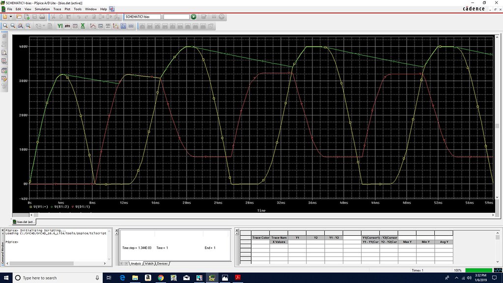
Here is the schematic of my pspice sim.
 bias sch by Dennis Kelley, on Flickr
And what the scope traces are supposed to look like.
 bias good sim by Dennis Kelley, on Flickr
I reasoned that what appears to be happening is the AC hv output of the transformer, while staying at 250 vac between them, is getting a DC offset. So I added a cap on the bias ckt side, and it kind of does it. Not quite. But notice here the pspice output looks more like my scope shots.
 bias sim by Dennis Kelley, on Flickr
Of course that cap does not exist in the circuit, or at least it isn't supposed to. I am thinking perhaps the power transformer has some sort of issue?
I put the variac on it, thinking perhaps it only happens at high voltage. But not, it drifts the same way with the AC line at 60 vac. It does stop eventually, at low voltage and full voltage.
So I am going to go stew for a bit, maybe play guitar or watch a little TV. My brain is tired of trying to understand things that don't make sense. You would think I would be used to it by now? But I just can't stand not knowing why.
I put a dmm on the hv secondary and set it to AC volts. When I powered it up it was rock solid at 250vac.
I put a second DMM on the B+, and while I watched the AC hv stay constant I could see the B+ steadily rise.
I put a scope probe referenced to chassis ground on the point where the hv secondary connects to the diodes. One channel on each of the leads. I could get a similar result by adding a DC offset into the output of the transformer output in my pspice simulation. I captured it after a few seconds and then waited a few more seconds and halted the scope and took a picture. You can see the earlier voltage levels on screen in white.
IMG_2806 by Dennis Kelley, on FlickrThe scope trace in yellow was the one connected to the same side as the bias circuit coupling cap.
Here is the schematic of my pspice sim.
bias sch by Dennis Kelley, on FlickrAnd what the scope traces are supposed to look like.
bias good sim by Dennis Kelley, on FlickrI reasoned that what appears to be happening is the AC hv output of the transformer, while staying at 250 vac between them, is getting a DC offset. So I added a cap on the bias ckt side, and it kind of does it. Not quite. But notice here the pspice output looks more like my scope shots.
bias sim by Dennis Kelley, on FlickrOf course that cap does not exist in the circuit, or at least it isn't supposed to. I am thinking perhaps the power transformer has some sort of issue?
I put the variac on it, thinking perhaps it only happens at high voltage. But not, it drifts the same way with the AC line at 60 vac. It does stop eventually, at low voltage and full voltage.
So I am going to go stew for a bit, maybe play guitar or watch a little TV. My brain is tired of trying to understand things that don't make sense. You would think I would be used to it by now? But I just can't stand not knowing why.
> Here is the schematic of my pspice sim.
That looks obscenely wrong to me. C6 bypasses D4?? I suspect you are taking your bias supply from the wrong side of the AC. Or that you took a bias plan for CT AC and put it on a FWB.
Find a known good plan with FWB and this type of side-train bias, and copy carefully.
Or put a 120V:12V transformer backward on a 6V line and rectify that 60V AC.
I am thinking there is a flaw in the design of the Fender Pro Jr amp. The hv secondary is floating and they connect it to a full wave bridge circuit. The output of the bridge provides the B+, with help from the filter caps. That works just fine, as long as I don't connect the power tube bias voltage circuit to the hv from the transformer.
There is nothing special about the bias voltage. Typical Fender capacitvely coupled with a diode to provide the negativ bias voltage, and a couple of caps to filter it, and resistors to set the voltage to -10.5V.
When I first connect it to the hv winding of the secondary, I see the -10.5V and B+ is around 350V, which is fine according to the schematic I have. However after a few seconds it starts to drift. The B+ starts to climb, and the bias voltage goes down towards 0V, down around -4V. The B+ goes up to 500V.
I have replaced or tested every part in the bias circuit. I experimented with what it takes to get it to start drifting. The coupling cap goes to a 58K resistor which is tied to ground. If I disconnect that or the coupling cap, then the B+ stops drifting.
What appears to be happening is that the hv winding on the power transformer starts to develop a DC offset. Not between the hv output leads line to line, but between them and the GND reference. A common mode voltage is somehow getting imposed onto both of the hv windings. You can see the scope capture waveform at the hv output leads of the PT above.
Somehow this offset gets added to the B+, and only 1 set of diodes in the bridge ever get turned on. The other diodes never conduct because the voltage on the positive cycle never reach the B+ voltage so they aren't forward biased. When that side goes negative it doesn't make it to GND or even try to make it below GND so the other diode doesn't turn on either. The diodes are all good mind you. They tested good, but I replaced themanyway.
This looks like a design flaw in the amp. I have ordered another PT out of frustration and a lack of what else to try. Hopefully that will fix it, but I am waiting for the transformer.
I reasoned that the bias circuit is causing some sort of imbalance, and the coupling cap is getting charged up. I think this has the effect of pushing the common mode voltage of the PT hv outputs. So I built a quick little circuit with the same 0.047uF cap and a 56K resistor to GND. I connected it to the hv output on the other side of the PT secondary. To my surprise this actually worked. So with a duplicate circuit pushing it back on both sides the DC offset stays near zero. The B+ goes to 320V and the bias voltage goes to -10.5 volts, and everything is stable.
Even though this works, I shouldn't have to do this. Fender knows what they are doing right? I'm not sure if I've ever seen a secondary B+ circuit that had no DC tie to GND at all. Usually they have a secondary with a center tap that is grounded. This has nothing. And as I said it works fine, until you hook up the bias voltage circuit.
Let's hope the PT fixes it.
Don't confuse a bridge (what you have here) and a full wave rectifier with the center tapped transformer.I'm not sure if I've ever seen a secondary B+ circuit that had no DC tie to GND at all. Usually they have a secondary with a center tap that is grounded. This has nothing. And as I said it works fine, until you hook up the bias voltage circuit.
There is nothing wrong with Fender's power supply. The ground return is on the DC side. Look at the schematic.
I still maintain you have a bad ground, or at least a bad connection somewhere. The bias dropping to zero is caused by your meter becoming a high impedance ground path. The higher than expected voltage is also caused by an improper return path to ground. Much like a voltage doubler circuit. One of your scope traces even shows there's no ground.
Check continuity from the anode side of CR1 or CR2 to ground, follow it through to the filter caps and so on.
You can also measure your voltage directly at the first filter cap (not using chassis as ground)
A DC offset will make the transformer buzz, and wouldn't give you such a high voltage change.
I've seen this behavior before, and come to think of it, I think it was on a Fender amp. Their boards are pretty poor quality and I've seen many flaws in them, from all kinds of models.
It would be good to provide a picture or link to the *specific* circuit. I don't want to get started on one, only to find out there was another model of the same name. (That's before a recent ruckas which said Bassman and was in fact a DeLuxe.)
I have attached the first Pro Jr plan I found but it may not be what YOU are working on.
Yes, it is possible a commercial circuit from a company with a 50 year history could be "flawed". Even after being signed-off by Designer, Draftsman, Checker, and Prototype Tech. I have seen some doozies. But more often I am mis-reading or mis-understanding the drawing.
Fender has done some eye-twisting schematics. This is nowhere near their worst.
Attachments
You'd be surprised what some strange grounding can do.
I suggest you start at the transformer and work your way through with volt meter. Do not use the chassis as ground, use the first filter cap. Follow the schematic carefully, and you'll eventually find the problem.
This is simple, don't overthink it.
I suggest you start at the transformer and work your way through with volt meter. Do not use the chassis as ground, use the first filter cap. Follow the schematic carefully, and you'll eventually find the problem.
This is simple, don't overthink it.
The PT came but made no difference. I tried adding the 0.01uF caps across the rectifiers, also no help
So I went ahead and added a 0.047uF cap and 58k resistor is series between the other hv line from the PT to gnd. That way both sides see the same load, and it does keep the B+ from drifting up to 500v.
I still feel like I am missing something, but I can’t find it, and this seems to work. I spent over 30 hours on this 1 amp, and I have other customers waiting. At least I did fix it. The previous tech just told mycustomer to not bring it back! I am only charging him 4 hours and I changed out 2 sockets. So I guess I earned $3 an hour on this one?
I have the spare PT. I may wire up a test circuit and just build the bridge and the bias circuit, and see if that has the same issue. If not, then I know there is something on that pcb causing it. But if my breadboard simple circuit has the same issue, then I know the mod I made was a good fix.
- Status
- This old topic is closed. If you want to reopen this topic, contact a moderator using the "Report Post" button.
- Home
- Live Sound
- Instruments and Amps
- Weird bias issue on Fender Pro Jr