Apologies first for the cheesy Princess Bride quote, and second for starting a thread that will probably seem similar to several others here. I couldn't find anything exactly like this, so here goes...
My goal is to design the output stage of a music instrument amp using a pair of KT-88s. Subject to the limitations listed, I wish to extract every Watt possible from these tubes. Every. Stinking. Watt.
I wish to eliminate or at least minimize crossover distortion, so Class B is out.
Although I'm a fan of Neil Young, blocking distortion is also a no-no.
I wish a pair of tubes to have a lifetime measured in months (years if possible) and not hours, so super hot-rodded lab curiosities are out.
I do not wish to have any solid-state devices beyond diodes in the signal path. Sorry, source-follower lovers. I do not object to them elsewhere in the design, for example, in a rectifier.
Edited to add: I don't want to use any tubes that can't be found at your local music store. So, things like 12AX7, 6L6GC, El84 are fine. 300B, KT120, 6SN7GT, probably not.
Aside from that, anything goes. I do expect to be hitting this output stage with some severely clipped signals from time to time, and to sometimes drive it into clipping regardless of what comes in the front door. So, any topology that fits the above is on the table, such as screen drive if that fits. I may be interested in winding my own transformers, so consider impedences as "free" and concepts like coupling transformers in play.
Here's a summary of what I've considered so far:
I consider everything to the right of the left-hand side of the Ra curve to be available, as if the tube was some sort of big diode. Given that, maximizing power with an acceptable tube life seems to be an exercise in drawing a class-B loadline that does not exceed an arbitrary plate-dissipation number. For that number, I have chosen 96 Watts, based on the fact that a couple of successful commercial designs have loadlines that are in the 94-97 Watt territory, namely the 200W Marshal Major and the Hiwatt DR201 and DR405 (about 200 W and between 300-400 W respectively). The Marshall and the DR201 use 2 pairs of KT-88s in push-pull, the DR405 3 pairs. I'm only using one pair, but I want to see if I can get more power than that from my pair by using clever design.
If I want to refer to previous work, I should also mention the Fender PS 300 and PS 400, which used 2 and 3 pairs of 6550As, rated at 42 Watts plate dissipation, in Class AB2. Va(o) was 700 V, Vg2 was 350 V, and I don't know what the load line was because I don't know the impedance of the output transformer. So, they may have been able to run at lower maximum instantaneous plate dissipation by getting more voltage swing and current swing via Class AB2 (or more power per pair at similar dissipation levels).
I figure worst case is a clipped input resembling a square wave at just the wrong signal level, which would give me a continuous plate dissipation of 48 W. The commercial amps survived that, the Marshall with about 60 V of sag at the center tap. I suspect the sag for the Hiwatts was minimal as both the output transformer and power transformer were huge.
Playing with loadlines, I find I maximize power up near maximum allowable B+ of 800 V, and output impedance at 6.7k Ohm. At the opposite end of the loadline, current swings up to about 430-440 mA at about 70 V. To get current up that high, I need Vg2 at least 350 V or so. Pout is a rather fabulous 158W, if my calculations are correct.
That led me to my first real obstacle. At that plate voltage and screen voltage, screen dissipation is unacceptably high, some 20 Watts or so with a clipped waveform. I began to look at Class AB2 operation for relief. I don't know much about AB2, but looking over the 6L6GC datasheets, I was led to believe that available plate current can be raised by either going to a higher screen voltage or by taking grid voltage positive, and that for a given available plate current, screen current will be about the same no matter which scheme is chosen. If that is true, I can lower screen dissipation by keeping screen (and plate) current about the same, and trading off screen voltage for grid voltage (not at 1:1, of course).
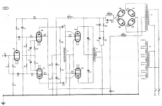
I started wondering how low I could go on the screen and how high I could go on the grid, and that led me to this circuit from the GEC KT-88 datasheet. It's a Class B circuit rated at 150 W with RL(a-a) at 6k Ohm "for speech only". 7.5k Ohm is recommended for "other purposes", and I estimate the circuit would produce maybe 120 W with that load.
Now, this is a Class B amp, but I'm more interested in what's going on inside the KT-88s. Under "Operating Conditions", it lists Vin(g-g)(rms) = 360 V. Just to verify this isn't a misprint, the text reads, "Both grids are driven into the positive region from a driver stage capable of providing 180+180V r.m.s., the current drawn by the control grids being limited by R18 and R19." R18 and R19 are listed as "22-100k Ohm 1W".
Maybe I'm just new at this, but if I understand this right, that means each grid is getting hit with a positive 255 V at peak. I struggle to comprehend KT-88 operation under those conditions.
So, let me summarize what I hope to learn:
Is there any other topology or arrangement which would allow me to extract more power from these tubes without blowing them up? Meaning, other than a more or less conventional Class AB2 grid-driven stage with fixed bias, or other than some variant of the attached schematic?
Is there any other way to lower screen dissipation at these power levels?
Can I modify the circuit in the attached schematic to run in Class AB2 instead of Class B? Or is there something that works even better?
Thanks for your advice and suggestions.
My goal is to design the output stage of a music instrument amp using a pair of KT-88s. Subject to the limitations listed, I wish to extract every Watt possible from these tubes. Every. Stinking. Watt.
I wish to eliminate or at least minimize crossover distortion, so Class B is out.
Although I'm a fan of Neil Young, blocking distortion is also a no-no.
I wish a pair of tubes to have a lifetime measured in months (years if possible) and not hours, so super hot-rodded lab curiosities are out.
I do not wish to have any solid-state devices beyond diodes in the signal path. Sorry, source-follower lovers. I do not object to them elsewhere in the design, for example, in a rectifier.
Edited to add: I don't want to use any tubes that can't be found at your local music store. So, things like 12AX7, 6L6GC, El84 are fine. 300B, KT120, 6SN7GT, probably not.
Aside from that, anything goes. I do expect to be hitting this output stage with some severely clipped signals from time to time, and to sometimes drive it into clipping regardless of what comes in the front door. So, any topology that fits the above is on the table, such as screen drive if that fits. I may be interested in winding my own transformers, so consider impedences as "free" and concepts like coupling transformers in play.
Here's a summary of what I've considered so far:
I consider everything to the right of the left-hand side of the Ra curve to be available, as if the tube was some sort of big diode. Given that, maximizing power with an acceptable tube life seems to be an exercise in drawing a class-B loadline that does not exceed an arbitrary plate-dissipation number. For that number, I have chosen 96 Watts, based on the fact that a couple of successful commercial designs have loadlines that are in the 94-97 Watt territory, namely the 200W Marshal Major and the Hiwatt DR201 and DR405 (about 200 W and between 300-400 W respectively). The Marshall and the DR201 use 2 pairs of KT-88s in push-pull, the DR405 3 pairs. I'm only using one pair, but I want to see if I can get more power than that from my pair by using clever design.
If I want to refer to previous work, I should also mention the Fender PS 300 and PS 400, which used 2 and 3 pairs of 6550As, rated at 42 Watts plate dissipation, in Class AB2. Va(o) was 700 V, Vg2 was 350 V, and I don't know what the load line was because I don't know the impedance of the output transformer. So, they may have been able to run at lower maximum instantaneous plate dissipation by getting more voltage swing and current swing via Class AB2 (or more power per pair at similar dissipation levels).
I figure worst case is a clipped input resembling a square wave at just the wrong signal level, which would give me a continuous plate dissipation of 48 W. The commercial amps survived that, the Marshall with about 60 V of sag at the center tap. I suspect the sag for the Hiwatts was minimal as both the output transformer and power transformer were huge.
Playing with loadlines, I find I maximize power up near maximum allowable B+ of 800 V, and output impedance at 6.7k Ohm. At the opposite end of the loadline, current swings up to about 430-440 mA at about 70 V. To get current up that high, I need Vg2 at least 350 V or so. Pout is a rather fabulous 158W, if my calculations are correct.
That led me to my first real obstacle. At that plate voltage and screen voltage, screen dissipation is unacceptably high, some 20 Watts or so with a clipped waveform. I began to look at Class AB2 operation for relief. I don't know much about AB2, but looking over the 6L6GC datasheets, I was led to believe that available plate current can be raised by either going to a higher screen voltage or by taking grid voltage positive, and that for a given available plate current, screen current will be about the same no matter which scheme is chosen. If that is true, I can lower screen dissipation by keeping screen (and plate) current about the same, and trading off screen voltage for grid voltage (not at 1:1, of course).
I started wondering how low I could go on the screen and how high I could go on the grid, and that led me to this circuit from the GEC KT-88 datasheet. It's a Class B circuit rated at 150 W with RL(a-a) at 6k Ohm "for speech only". 7.5k Ohm is recommended for "other purposes", and I estimate the circuit would produce maybe 120 W with that load.
Now, this is a Class B amp, but I'm more interested in what's going on inside the KT-88s. Under "Operating Conditions", it lists Vin(g-g)(rms) = 360 V. Just to verify this isn't a misprint, the text reads, "Both grids are driven into the positive region from a driver stage capable of providing 180+180V r.m.s., the current drawn by the control grids being limited by R18 and R19." R18 and R19 are listed as "22-100k Ohm 1W".
Maybe I'm just new at this, but if I understand this right, that means each grid is getting hit with a positive 255 V at peak. I struggle to comprehend KT-88 operation under those conditions.
So, let me summarize what I hope to learn:
Is there any other topology or arrangement which would allow me to extract more power from these tubes without blowing them up? Meaning, other than a more or less conventional Class AB2 grid-driven stage with fixed bias, or other than some variant of the attached schematic?
Is there any other way to lower screen dissipation at these power levels?
Can I modify the circuit in the attached schematic to run in Class AB2 instead of Class B? Or is there something that works even better?
Thanks for your advice and suggestions.
Attachments
Last edited:
in your actual build you may find that arcing between pins 3 and 4 can happen this is an obstacle you have to work on...
that is why top caps for b+ of 800 volts or more are common practice...
your other obstacle is plate dissipation ratings, never exceed them if you want your amps to live a longer life...
that is why top caps for b+ of 800 volts or more are common practice...
your other obstacle is plate dissipation ratings, never exceed them if you want your amps to live a longer life...
Tubelab has a black belt in extracting power far beyond the traditional datasheet examples. He got 90 W from cheap Chinese 6L6GCs, so more can be expected from KT88s. Of course he uses source followers, but you can replace those by cathode followers. Just use a type with ample current capability. A pair of EL84 comes to mind. Screen drive really only works well with tubes with sensitive screengrids. The traditional audio valves have insensitive screens, hence the high voltage rating. Low screen voltage ratings are an indication that the screens might be sensitive enough to be used as a control grid (TV sweep tubes). As Tony pointed out: the risk of arcing at the base get very real when you use very high supply voltages. That's why the anode voltage ratings of the TT21/22 are in the kV range and for the KT88 you're taking risks with 800V. Topcap for the anode instead of right next to a heater pin. Inside they are the same.
...I wish to extract every Watt possible from these tubes. Every. Stinking. Watt.
....I wish a pair of tubes to have a lifetime measured in months (years if possible) and not hours...
Make up your mind. All machines wear faster when worked harder. The Hemi car engine can make 250HP for 100K miles, or 2,500HP for 1/4 mile.
The early Ampex quad recorder used KT-88-type tubes for FULL 50 Watts (driving motors) and the tubes lasted from Ike to JFK for NBC, and into Nixon days in non-network service.
Do you really need WATTS!! ? Or DISTORTION? Pick a reasonable power supply and load, beat the heck out of the grids, it will distort to the max.
If you need Watts! to compete with a drummer (like racing a Hemi on the 1/4 mile), USE MORE TUBES! That is how real designers get POWER. Aircraft engines grew from 4 to 8 and 12 and even 28 cylinders. When mid-war a tank needed an engine of that power, they put 42 cylinders (seven Plymouth Six car engines) together, and it did the job fine.
However it is post-20th-century. We have transistors now! After many failures they are now more reliable and bigger and cheaper than tubes. Even Neil Young does it! The 16W DeLuxe is micced-up and feds the 16,000W main and monitor systems. His drummer doesn't stand a chance.
So noted. Clearly, existing commercial designs have dealt with this; the PS 300 and PS 400 have B+ of 700 V, and that's before we count induced voltage from the transformer. Do you have any recommendations for sockets and/or construction details that would minimize this possibility?in your actual build you may find that arcing between pins 3 and 4 can happen this is an obstacle you have to work on...
I will probably wind my own output transformer, and will be quite conservative with regard to transformer insulation. Of existing commercial designs, the Marshall Major has a measured B+ of 666 V in ultralinear, and did have problems with arcing from one transformer vendor (but not with Partridge). Arcing could happen anywhere, but was predominantly found in the output transfomer compared to the sockets.
The 96 W was based on loadlines of amps that working musicians gigged with, including some of the biggest names in the buisiness. Some had roadies that changed tubes for every show, others had amps that seemed indestructable (Hiwatts, especially). It may be that I'm underestimating the protective effect of sag and the way sag shifts the loadline to the left If so, I can adjust the design...just so long as the adjustment is made before the output transfomer is wound.your other obstacle is plate dissipation ratings, never exceed them if you want your amps to live a longer life...

It would be very nice if I had quiescent and full-load measurements on some of these amps. If anyone here works on them and has one pass through your shop...
I'm hoping he chimes in here, I'd be interested in what he has to say.Tubelab has a black belt in extracting power far beyond the traditional datasheet examples.
Do I understand correctly that the GEC circuit that I attached to my first post is some kind of combination screen drive and grid drive?Screen drive really only works well with tubes with sensitive screengrids. The traditional audio valves have insensitive screens, hence the high voltage rating.
Refer to my reply to Tony, I'm collecting best practices for pushing the sockets as high as they can safely go, and am willing to back off from 800 V if there is no other way.As Tony pointed out: the risk of arcing at the base get very real when you use very high supply voltages.
Refer to my previous two posts regarding how hard to push. My thoughts are that if reliability is good enough for mass produced commercial amps, it's probably good enough for me.Make up your mind. All machines wear faster when worked harder. The Hemi car engine can make 250HP for 100K miles, or 2,500HP for 1/4 mile.
Yes. Both.Do you really need WATTS!! ? Or DISTORTION? Pick a reasonable power supply and load, beat the heck out of the grids, it will distort to the max.
Every amp breaks up in a slightly different way, and which is preferable musically is a matter of taste. I'm interested in finding out what happens when you build an amp to maximize watts, and then drive it to break up. What does it sound like? One way is to build it and find out. But there might be people here who can take an educated guess at it if I have a design. But first, I have to come up with a design. So...here I am. Let's maximize watts given a level of reliability, and assume we'll drive it into clipping.
I can copy existing designs and get to 500 watts without too much difficulty (would probably weigh over 100 lbs, but that's another story). That's not the goal here. I want to see what I can do with two tubes. In the extremely unlikely event that isn't enough, I can add more.If you need Watts! to compete with a drummer (like racing a Hemi on the 1/4 mile), USE MORE TUBES!
I originally posted this in the Tubes subforum because I thought it would get more into topologies and tube operating theory; the mods moved it. I'm not complaining, just pointing out that this is not another, "What mods can I make to my Twin Reverb to make it louder?" thread.
Is there any other way to lower screen dissipation at these power levels?
- Yes, there are development in technology since 1957 allowing to monitor the grid current and automatically readjust the biasing. This is very handy when driving expensive triodes like 845, 300B to their maximum dissipation.
In your case, install a current meter to the cathode. Excessive temporary grid current should not damage quality KT88. However remember that quality of 1950s kt88 is not the same than new KT88, I expect less robust new tubes.
The good news : there is the KT120, more distortion at 50 Watt than KT88 , however to reach 100 Watt they can do it better.
For the price, KT120 are really a no brainer to KT88 nowaday.
Can I modify the circuit in the attached schematic to run in Class AB2 instead of Class B
the circuit above is overkill, normal 6sn7gt followers can driver your KT tubes (they are super easy to drive, not like 300B, driver killers). No need for interstages.
No need for quad tube rectiver per amp. Just use power diodes on heatsinks.
Most important, don't be shy to get an oversize output transformer, a rating of 150, 200 watt is good too. If you limit it to 100 Watt THD from the transformer will be quite high and it adds up quickly to the tube saturation.
Last edited:
Can you point me to a reference?- Yes, there are development in technology since 1957 allowing to monitor the grid current and automatically readjust the biasing.
Where can I find out what is excessive grid current? It's not in the tube data sheets.In your case, install a current meter to the cathode. Excessive temporary grid current should not damage quality KT88.
In my first post, I should have also said that I wish any tube in the design to be available at a generic music store. So, things like 12AX7, 6L6GC, EL84, no problem. KT120, 6SN7GT, not so much. Part of the reason I chose KT88s was because they are the highest speed, lowest drag output tube commonly found in such places.The good news : there is the KT120, more distortion at 50 Watt than KT88 , however to reach 100 Watt they can do it better.
I'll edit my first post to include this constraint.
At this stage of the game, I'm just trying to figure out what I want each component of the power tubes to do: fix to a certain voltage, follow the input, follow the output, etc. Once I understand what needs to happen at each pin, I can go about figuring out how to do it with the tubes available to me. But thanks for the advice about cathode followers.the circuit above is overkill, normal 6sn7gt followers can driver your KT tubes (they are super easy to drive, not like 300B, driver killers). No need for interstages.
Yeah, I wasn't going to slavishly copy every portion of that circuit, including technology that had been abandoned by the mid-1960s. Mostly, I was just trying to figure how how it worked, since I'd never seen an output stage that looked like that before.No need for quad tube rectiver per amp. Just use power diodes on heatsinks.
Most important, don't be shy to get an oversize output transformer, a rating of 150, 200 watt is good too. If you limit it to 100 Watt THD from the transformer will be quite high and it adds up quickly to the tube saturation.
I'm thinking more and more about winding my own, designing from a reference like Wolpert or something like that. I think that if I design for adeqate bass response under load, I should be ok.
So noted. Clearly, existing commercial designs have dealt with this; the PS 300 and PS 400 have B+ of 700 V, and that's before we count induced voltage from the transformer. Do you have any recommendations for sockets and/or construction details that would minimize this possibility?
I will probably wind my own output transformer, and will be quite conservative with regard to transformer insulation. Of existing commercial designs, the Marshall Major has a measured B+ of 666 V in ultralinear, and did have problems with arcing from one transformer vendor (but not with Partridge). Arcing could happen anywhere, but was predominantly found in the output transfomer compared to the sockets.
The 96 W was based on loadlines of amps that working musicians gigged with, including some of the biggest names in the buisiness. Some had roadies that changed tubes for every show, others had amps that seemed indestructable (Hiwatts, especially). It may be that I'm underestimating the protective effect of sag and the way sag shifts the loadline to the left If so, I can adjust the design...just so long as the adjustment is made before the output transfomer is wound.
It would be very nice if I had quiescent and full-load measurements on some of these amps. If anyone here works on them and has one pass through your shop...
i have had arc over on sockets at B+ of 440 volts dc....i was using a Cinch octal socket...the better alternative would be to use tubes with top caps like the TT21/22 a kt88 equivalent..
Why? A 50W amp clipped hard is stupidly loud.So, let me summarize what I hope to learn:
Is there any other topology or arrangement which would allow me to extract more power from these tubes without blowing them up? Meaning, other than a more or less conventional Class AB2 grid-driven stage with fixed bias, or other than some variant of the attached schematic?
What do you actually intend to "learn"? You've told us what you want to do. I'm struggling to understand what you think you'll learn that's not already been documented to death in the last half century.
If you want to get more power out of a pair of tubes, the instructions are out there. Regulate the hell out of it, pile on the iron, add the belts and braces that are available to stop it blowing up. And pick a tube with a topcap (e.g. 807 instead of 6L6) Find a good datasheet like the STC one for the 807 (all 43 pages) and it'll tell you everything you need to do to get 75W from a pair of them. Including how to wind all the iron. Add some modern tips from the Immortal Amp series; plus some modern bias setting/monitoring, adjust all the circuit values for KT-88 and that's it.
I suggest you get some more efficient speakers.Thanks for your advice and suggestions.
Last edited:
i have had arc over on sockets at B+ of 440 volts dc....i was using a Cinch octal socket...the better alternative would be to use tubes with top caps like the TT21/22 a kt88 equivalent..
Were those ceramic, or bakelite, or what? If your goal is to sensitize me to the hazards of high voltage, you've succeeded. I've learned a fair bit about sockets and arcing in the last couple of days.
My apology for missing it in my original post (since corrected), but I want to limit myself to tubes that might be found at a local music store. I've never heard of a commercial musical instrument amp that used tubes with top caps (and if one ever existed, I'm sure someone here will mention it!) On the other hand, I can go down today and buy an amp with 600 V on the B+, with no top cap, and consumer amps have been produced in the past with even higher voltages.
If I can't do 800 V with a KT-88, I won't. But the manual says 800 V, and the old version of the manual even says you can go to 850 under certain circumstances. If I can't get sockets like they made back then, I'll back off.
For starters, I hope to learn how I'm going to do it. At this point, I don't know if there is any nonstandard (from the point of consumer MI amps) topology that will outperform what you see in most Fenders and Marshalls. I don't know exactly how the circuit I attached works...I think it drives through both the screens and the grids, but I've never heard of anything like that. I don't know what I can do in Class AB2 that I can't do in Class AB1...not the difference in the two classes of operation, but what that can translate to at the speaker jack. I don't know what my B+ is going to be or what my RL(a-a) is going to be (I have a current best-guess, but I'm willing to change if I get a new load of brains).What do you actually intend to "learn"? You've told us what you want to do.
I've plowed through several hundred pages of references, from the practical to the theoretical in the last few days. I don't even know if there's something I should be reading that I'm not. Basically, I want to acquire enough knowledge to make choices here, and then be able to defend them.
Find a good datasheet like the STC one for the 807 (all 43 pages) and it'll tell you everything you need to do to get 75W from a pair of them.
Alas, I am unable to find such a comprehensive reference on the KT-88. But since I've managed to learn a few things from the 6L6GC datasheets, I'll take a peek at the 807 stuff.
Thanks for the Immortal Amp tip, there's some good stuff in there.Add some modern tips from the Immortal Amp series; plus some modern bias setting/monitoring, adjust all the circuit values for KT-88 and that's it.
That'll make my Twin Reverb louder? Kewl!!I suggest you get some more efficient speakers.
guitar amps are made not for its robustness but by the way it distorts the sound when driven hard, if you are a guitarist you will know what i am talking about...
i once made a cone of the 18 watter spitfire amp, one with the usual el84/6bq5 tubes, and the other with the 6w6 tv vertical scaning tubes....guest what a guitarist chose?
do not confuse guitar amps with amps for high fidelity, they are two different animals altogether....and this probably is the first thing you should come to understand...
Since we're in the "instruments and amps" section of diyaudio, I'm assuming you want loud over super fidelity. So... Do what Hiwatt did in the DR201 and run the KT88s like in that amp. That means 720-750 volts on the plates and 400-420 volts on the screens. Operating a pair of KT88s this way will probably get you the most watts and still have the KT88s run stable. You will get 100 watts per pair this way, working into a 4500 ohm plate to plate load. What is important is that you will need to use VERY GOOD quality ceramic octal sockets, like old stock Amphenol or the like... Don't use el cheapo Chinese ceramic sockets, they wont last. The Hammond 1650N output transformer works well for this setup. I've used KT88s this way for a few years now and have had very good results this way. As for more power, you will have to up the plate voltage but 750 volts is already really pushing it for octal tubes/sockets. I wouldn't push it any harder as the benefits will be minimal and the chances of failure go up rapidly. And DON'T even think about running the screens at more than 400-420 volts because they WILL fail with any more voltage on them. Good luck...
P.S. 807s are a good idea as they have plate caps but they are prone to oscillation so good practice has to be done in the design of the output stage. As stated above, 75 watts is about the max from a pair of 807s; maybe a bit more if class AB2.
P.S. 807s are a good idea as they have plate caps but they are prone to oscillation so good practice has to be done in the design of the output stage. As stated above, 75 watts is about the max from a pair of 807s; maybe a bit more if class AB2.
Last edited:
I presume you've got a copy of the RDH?I don't even know if there's something I should be reading that I'm not.
And read everything that the Valvewizard wrote? As well as Rob Robinette, who I mentioned earlier, there's a bunch of other people who've gone through and analysed various guitar circuits (e.g. AmpBooks)
Then there's probably a dozen or so threads worth reading here and in Tube Audio, like the 6L6 AB2 thread
For bonus points, work your way through tubelab_com's postings. There's several books worth of material there, if only we can find him an editor
On "weird ways to drive a valve", get every copy of Sound Practices you can find (e.g. here and the associated Joelist postings) as the lunatic fringe of tube HiFi (and I mean that in a most positive way) spent the last quarter century trying and forensically analysing every historical circuit they could find (e.g. this) and making weird stuff up (like the "monkey" and the "free lunch").I don't know exactly how the circuit I attached works...I think it drives through both the screens and the grids, but I've never heard of anything like that.
Do take your sense of humour and perspective with you, as some of that crowd were channeling Hunter S. Thompson!
Last edited:
> On "weird ways to drive a valve"
I don't think he should be smoking the weird weeds. This is NOT a new path. Fender, Marshall, Hi-Watt, Ampeg have beaten these bushes before us, specifically seeking "guitar tone" (not "hi-fi", not telephony or talking-pictures).
That few commercial guitar amps use the costly 6550/KT88 is no real matter. They are just big 6L6. Same floor-plan, with higher voltage and current.
Tubelab has a black belt in extracting power far beyond the traditional datasheet examples........I'm hoping he chimes in here, I'd be interested in what he has to say.
I thought about it earlier, but you shot down what I was going to say in the first few sentences of your first post.
Extracting 100 watts per pair from KT88's is not hard, but I used mosfet drivers, you have vetoed that idea. Getting 250 watts from a pair of $15 tubes isn't too hard either, but they were TV sweep tubes with top caps, also driven with mosfets, breaks three of your criteria.
I've never heard of a commercial musical instrument amp that used tubes with top caps (and if one ever existed, I'm sure someone here will mention it!)
Without Googling I can immediately name two, and I have seen guitar amp schematics with 807's but they were old, the 807's were super common and cheap right after WWII......
The first generation Ampeg SVT bass amp made 300 to 400 watts from 6 X 6146 transmitting tubes. The amps unfortunately had a nasty habit of spontaneously self destructing, often spectacularly with fire and smoke! Ampeg had ignored the screen grid ratings on the output tubes leading to disaster. The SVT would be redesigned to use 6550's and live on in tube amp form for a long time. There is also a solid state bass amp with the same name.
McIntosh (of HiFi amp fame) made the MI-350 amp used in the Grateful Dead's wall of sound, and at large outdoor festivals like Woodstock. It used 8 X 6LQ6 TV sweep tubes for 350 to 500 watts. As with most McIntosh stuff, super reliable and under rated.
in your actual build you may find that arcing between pins 3 and 4 can happen.....I've managed to learn a few things from the 6L6GC datasheets, I'll take a peek at the 807 stuff.
My experience with arcing in guitar amps has been from pin 3 (plate) to pin 2 (heater). If the heater circuit is grounded the arc may just blow the tube and maybe the socket, if the amp is properly fused. If not the OPT and possibly the power transformer can be fried. If the heater circuit is elevated with the usual two resistors and cap, these parts, a 12AX7 or two, and maybe the power transformer can be killed. Why?
In a normal HiFi amp the plate voltage on the output tubes will approach TWICE the B+ voltage. This assumes the amp is not driven to clipping AND a load impedance is attached to the speaker terminals that is close to the amps rated load, and not totally reactive..... NONE of these apply to a cranked guitar amp.
Ever play with an OPT and a 9 volt battery (or an ohmmeter) and zap yourself stupid, then wonder how you got shocked from 9 volts? I have measured over 2500 volts on the plates of a functioning guitar amp running from a 450 volt supply. How is this possible?
Do we ever dial the overdrive pedal up to 11, then dime all the controls? When you do this the output tubes are actually operating like on - off switches alternately putting B+ across either half of the OPT.
All speakers have a mechanical resonance where the electrical impedance rises to a value well above its rated impedance. 30 to 40 ohms is not uncommon on an 8 ohm speaker. The resonant frequency of most guitar speakers is IN the guitar's normal frequency range, so somewhere on the neck in the 5th or 6th string that amp will be almost unloaded, and its plate voltages will be stupid high.
The 807 IS a 6L6GA in a 5 pin base with a top cap. The 6GB6 IS the same tube in an octal base with a top cap. These tubes were introduced for applications where high plate voltages were needed. This was because of the arcing in 6L6GA designs (long before the 6L6GC was introduced). All of the common audio tubes found at a guitar shop will have the same pin 3 to pins 2 or 4 issue because they are all pinned the same, except for pin 1 in the EL34.
Even if you have tube sockets made of pure Kryptonite, the arc can occur INSIDE the base of the tube, or across the bottom of the base or the socket. Do amps ever get dirty? Do they ever see use in dusty, smokey, damp, or humid environments? The dust and dirt will accumulate in the tube base between the glass and the phenolic (or metal) and create the path for an arc to start.....then its over....poof! Those old amps that ran the KT88's on 600 volts or more are mostly dead now, for this reason. So I wouldn't venture much beyond 500 to 550 volts on these tubes, but if you must, use good quality old stock ceramic sockets and thoroughly clean them before use.
Want a place to start, look at the GE data sheet for the 6550A. The 'typical operation' characteristics show 100 watts from a pair of 6550A's from 600 plate volts into a 5,000 ohm load in AB1. G2 is run from a 300 volt supply. That design will work, but expect to see somewhere over 4,000 volts on the tube sockets and OPT when you "set the controls for the heart of the sun." Peak power will be over 150 watts at about 40% distortion.
I can do the same thing on a bit over 450 volts with a 3300 ohm load and AB2.
As you surmised squeezing max power out of any pentode stresses the screen grid. You can relieve some of this stress by driving G1 positive and lowering the voltage on G2. The impedance of G1 transitions from near infinite, to less than 1K ohm when the grid goes positive, and drops rapidly as G1 is driven further positive. In order to avoid some ugly distortion a low impedance driver is required, and it must be capable of sourcing some current without distortion. The optimum component for that job is a mosfet.
Although I'm a fan of Neil Young, blocking distortion is also a no-no.
Blocking, AKA "farting out" is caused by grid current sucking the charge out of the coupling cap, thus disturbing the bias on the output tube......don't want blocking, ditch the coupling cap. There are two ways to do this, a driver transformer or a follower.
Don't want a mosfet, then find a suitable tube from your "approved list" with sufficient Gm to make a decent follower. I have successfully used the 5687 tube, but I suppose you could try the EL84.
each grid is getting hit with a positive 255 V at peak......the text reads, "Both grids are driven into the positive region from a driver stage capable of providing 180+180V r.m.s., the current drawn by the control grids being limited by R18 and R19
This method of driving both grids at the same time has been done since WWII. It was often used for high power PA amps for speech where distortion was not a problem. Stupid high amounts of drive voltage are needed. Most of this drive voltage is fed directly to the screen grid, and some is fed through a resistor to G1. The resistor limits the flow of current through G1 so it doesn't melt, but both grids together control the electron flow through the tube. Linearity isn't so good and distortion runs in the 10% range.
Some of us have improved this technique greatly since these "class B" amps were made. They now run in AB2 and make HiFi quality sound. You can search through the "Tubes" forum for terms like "Dual Drive" "Twin Drive" and "Crazy Drive." I am currently working on a new implementation of this. The usual tube for this job is however a TV sweep tube, and most of the typical guitar store tubes will not work well due to their insensitive screen grid.
So, I looked into that, and set off designing an output transformer just to see what I was getting into. This is all preliminary, but I have everything in a spreadsheet so that I can change all the numbers and crank out something different in seconds.Most important, don't be shy to get an oversize output transformer, a rating of 150, 200 watt is good too. If you limit it to 100 Watt THD from the transformer will be quite high and it adds up quickly to the tube saturation.
6700 Ohms Primary, 16/8/4 Ohms Secondary
Turns ratio is 20.46:1 (for the 16 Ohm tap)
Spec for 160 Watts
Primary Vrms is 1035
Primary Irms is 155 mA
Secondary Irms is 6.3 A at the 4 Ohm tap
2642 turns of 29 gauge on the primary
128 turns of 13 gauge on the secondary
Lamination is standard 1 3/4 inch
(External dimensions are 5 1/4 high X 4 3/8 wide)
Stack laminations 2 1/2 inches thick
Need at least 2 winding interleaves to keep high cutoff over 20k Hz...not a problem for a center-tapped primary.
DC resistance of primary is 207 Ohms
DC resistance of secondary at 16 Ohm tap is 0.248 Ohms
Normalized DC resistance of entire transformer is 311 Ohms
Insertion loss is 4.64%
THD at max output is 2.1%
Weight of laminations is 12.3 lbs
Weight of copper is 2.98 lbs
Weight of laminations + copper is 15.3 lbs
I hope that satisfies you that I'm not going to put some cheesy 50W OPT on it. For comparison purposes, the magnetic design is very similar to the 200 W OPT that Hiwatt put on the DR201, except that I'm using 2.5" of laminations, and Partridge only put 2" on that.
And to put it mildly, I learned a lot about OPTs from this little exercise.
Design calculations came from the Audio Transformer Design Manual by Robert G. Wolpert.
I think we're on the same page. By robust, I mean "built like a tank".do not confuse guitar amps with amps for high fidelity, they are two different animals altogether....and this probably is the first thing you should come to understand...
And I'm starting to understand this might sound somewhat Hiwatt-ish, where it starts out clean...turn it up, still clean...more, still clean...then it starts to clip and Ragnarok happens. I don't know if it'll have that "Live at Leeds" sound, but that's a possibility.
I've been wondering about this. The schematics show 650 V on the high rail and 410 V on the low rail, but I question that. Both are powered from full-wave bridge rectifiers, and the low rail is off a 280 V tap and the high rail from a 170 V tap. 1.41 X 280 = 396 VDC and 1.41 X 170 = 240 V. So, more like 396 screens (close) and 636 plates (not so close, certainly not to 720-750).So... Do what Hiwatt did in the DR201 and run the KT88s like in that amp. That means 720-750 volts on the plates and 400-420 volts on the screens.
(Schematic is from hiwatt.org. listing the Partridge TH1183 as the reference power transformer...this is the 3 pair version, but the voltages are the same on the 2 pair schematic.)
I hear that the modern Hiwatt clone makers run a higher B+ than that, but unless I see a little proof, I'm skeptical.
Enough different people in this thread have mentioned this to properly sensitize me to the danger. I note that since tubes are much more expensive than sockets, cheap sockets do not seem like a good place to economize.What is important is that you will need to use VERY GOOD quality ceramic octal sockets, like old stock Amphenol or the like... Don't use el cheapo Chinese ceramic sockets, they wont last
Thanks for the advice.As for more power, you will have to up the plate voltage but 750 volts is already really pushing it for octal tubes/sockets. I wouldn't push it any harder as the benefits will be minimal and the chances of failure go up rapidly. And DON'T even think about running the screens at more than 400-420 volts because they WILL fail with any more voltage on them.
- Status
- This old topic is closed. If you want to reopen this topic, contact a moderator using the "Report Post" button.
- Home
- Live Sound
- Instruments and Amps
- KT-88s: To the Pain