But I'm wondering what happens if the MOV starts conducting at the same time the corresponding output valve is also conducting hard. B+ is now clamped to ground directly via the MOV and valve in series.
Let's assume B+ is 500V and the MOV breakdown (for a single or for a string) is 1500V, just to make the numbers easy.
I think there are two cases.
The first is that the tube is in full conduction, plate voltage is very low, high current flows from B+ through half of the OPT to the plate and then through the cathode to ground. Now the signal changes, and because we're in heavy clipping, the tube current cuts off like a switch. Because current in the transformer windings cannot instantaneously go to zero, voltage piles up on the plate. When it reaches +2000V, the MOV "closes" and acts like a shunt from the plate to B+. Plate voltage is clamped to +2000V until enough current flows through the MOV to B+ to collapse the magnetic field in that half of the primary winding.
The second case is that the tube is in cutoff, at or very close to B+ and flowing little or no current. Since we're in Class AB instead of Class B, we'll say that a little current is flowing. Even through there is little current flowing through the corresponding primary half winding, the substantial current in the other half of the winding (that has just been cut off) has created a magnetic field that induces a voltage in the half of the primary winding that has "just been switched on". This induced voltage is negative with respect to B+ and can take the plate below 0V. Since "all tubes are diodes", plate current doesn't flow until the tranformer magnetic field collapses enough for the induced voltage on the plate to reach zero...or higher, if the tube actually obeys the diode line.
In this second case, the MOV doesn't shunt unless the plate drops below -1000V. And the tube dosn't really start conducting until the field collapses enough for the induced voltage in its half of the primary rises up near 0V, by which time the MOV should have stopped conducting and we've established a proper 500V drop from B+ to plate in that half of the primary winding.
So, unless my understanding of how all this works is faulty, I don't think the MOV causes any problem. It always maintains some rated voltage across its terminals, but once you exceed that voltage, it flows current "as needed" until either the transient passes or the magic smoke gets let out. Hence, in designing the protection, it is important to keep the MOV breakdown voltage greater than B+ and smaller than the insulation breakdown of the OPT.
I think I'm now ready to start designing a test rig to do the "knob twisting" that Tubelab_com mentioned in post #92.
I think I need to acquire, at a minimum, a chassis, some quality sockets, at least one and possibly several pairs of KT-88s, an output transformer, some big load resistors, some means of providing B+ adjustable from X00 to Y00 volts, some means of providing adjustable screen voltage and grid bias, and an adjustable square wave signal for the grid. I also need some way to measure and/or display various voltages and currents (1 ohm resistors work well for current), protection for various bits (fuses and MOVs), maybe even a little fire extinguisher Just In Case. I'll probably come back and add the capability to put a signal on the screens before I'm done.
What did I forget? Feel free to point me to a thread here or a reference elsewhere. I'm willing to wind my own transformers and similar things if that will save a buck here or there. So long as it doesn't compromise safety or the accuracy of the results, I'm probably open to it.
Hi Gnobuddy,But I'm wondering what happens if the MOV starts conducting at the same time the corresponding output valve is also conducting hard. B+ is now clamped to ground directly via the MOV and valve in series. Will a fuse in the B+ line be enough to protect the output valve under these conditions?
at least for PP amps this issue can easily be avoided by placing the MOV, or a spark gap, across the primary, from plate to plate. I've seen this in many commercials amplifiers from the 1950ies and earlier that work at higher plate voltages of about 800 V (two EL34's or EL156's!) and more.
Best regards!
If transformers had no leakage inductance, and loudspeakers behaved like pure resistors, then I agree with you 100%.<snip>
I think there are two cases.
<snip>
But George mentioned having seen anode voltages well below zero, and also much higher than 2 B+. Neither of these conditions is possible if transformers had no leakage inductance, and speakers were purely resistive. So we have demonstrated evidence that in reality, the output stage can end up operating in regions that simply don't show up when we draw nice resistive load lines on a set of anode curves.
Part of the answer probably lies in the fact that a loudspeaker is a voltage generator once the cone is set in motion. Thump the speaker coil with a short hefty pulse, that gets the cone moving, and now the speaker will continue to generate a voltage long after the drive pulse ended, until the voice coil eventually stops moving. The cone probably executes damped oscillations before it stops moving, so probably it will be pumping an erratic AC voltage back into the output transformer.
Can this back-emf cause anode voltage to fly well above B+ while the associated output valve is still conducting? I don't know. But I wonder.
It's a bit like the fabled warnings on ancient maps: "Hic sunt dracones" - "Here be dragons." Should we worry, or is our dragon-proof ship's armour simply a waste of time, effort, money, and cargo capacity?
Perhaps your test-bench will yield some answers - but only if you end up testing with an actual loudspeaker instead of a resistive dummy load. And what sane person tests a horrendously loud guitar amp at full blast with an actual loudspeaker?

-Gnobuddy
This effectively shorts the two anodes (plates) together while the MOV is in conduction. I'm trying to imagine what happens to transformer and valve currents during that instant, and I realize I have no proper mental picture to explain what the heck is going on.... placing the MOV, or a spark gap, across the primary, from plate to plate.
Perhaps part of the answer is that valves are very robust to extremely brief bursts of overcurrent, unlike semiconductors?
-Gnobuddy

So nominally 123 dB SPL @ 1 metre.200 watts into a pair of 100dB speakers........
Possibly 126 dB, as a pair of close-coupled 100 dB speakers will have twice the cone area of a single speaker, and therefore a 3 dB increase in efficiency (at least at frequencies where speaker diameter is much less than the wavelength.)
At 123 dB SPL, using the approximation that every 3 dB increase in SPL halves the tolerable exposure time before onset of hearing damage, we can expect hearing damage after approximately 4 seconds. Or 2 seconds at 126 dB.
Some relevant info here: Permissible Exposure Time for Noise SPL sound pressure level and duration Guidelines How long can a person endure a certain noise level before hearing damage occurs health sound level noise hearing ears impairment tinnitus damage - sengpielaudio Seng
Since SPL levels are inexact, and so is the assumption that our ears time-to-damage is logarithmic (halving for each additional 3 dB increase), we are essentially talking about virtually instantaneous hearing damage.
A second source ( Common Misconceptions about Hearing ) agrees with that opinion, stating "Recommended maximum allowable exposure times (by Nova Scotia Department of Labour) are.....0 min for above 115 dBA sound (there should be no exposure at this level!)"
If I had my life to live over, one change I would make would be to take better care of my hearing. I drove a noisy '73 Plymouth Road Runner for years, and that left me with some tinnitus in my left ear. Hearing damage is cumulative, and I found to my shock a few months ago that a short sit-in with a live band was enough to worsen my existing tinnitus. This wasn't a particularly loud band, either.
-Gnobuddy
But George mentioned having seen anode voltages well below zero, and also much higher than 2 B+. Neither of these conditions is possible if transformers had no leakage inductance, and speakers were purely resistive. So we have demonstrated evidence that in reality, the output stage can end up operating in regions that simply don't show up when we draw nice resistive load lines on a set of anode curves.
But for my analysis to be correct, that doesn't matter. I totally expect the OPT to do all these horrible, nasty things. Note that in my example, the plate voltage got to 4 x B+ at the high end, and -2 x B+ at the low end.
It's not my assumptions about the OPT that I'm worried about, it's my assumptions about how MOVs work. Which is why I spent some quality time with MOV characteristics curves and reading papers about MOVs before I wrote that up. I could still be wrong, though.
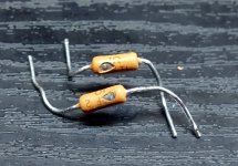
My big worry is that even mil-spec NOS ceramic sockets are only rated for 1250V pin-to-pin, which is less than 2 x B+ for many commercial guitar amps. Just how exactly do I size my MOVs? If they are greater than the OPT winding breakdown voltage, my OPT does a great job of being a sacrificial fuse to save my MOVs. And if they are less than 2 x B+, the MOVs won't last past the first jam session, even if there is no arcing.
If B+ is at 600 V, the space between 2 x B+ at 1200 V and the point where my sockets could (theoretically) arc at 1250 V is a little small...which would mean my output tubes become sacrificial fuses to save my OPT.
So it's been about a year and a half, some of that time was spent reinventing the wheel with regard to test equipment (and chasing up a few blind alleys), some with health issues (all resolved satisfactorily), and some with other projects.
It has really helped to take some time off and to look at this after a hiatus. Things have become at least a little clearer.
First, Ik, cathode current. Somehow, I overlooked that, or perhaps I just wasn't thinking clearly. DC Ik for a KT-88 is given as 230 mA. I understand that you can exceed that by a factor of 3 "briefly", but for push-pull operation with worst-case square waves, it seems clear to me that the limit is a factor of 2.
But Ik = Ip + Is + Ig, right? (If I am in class AB2, there will be some Ig.) So, I went back to the 6L6GC datasheets (which have curves for positive grid operation), and had an epiphany. There may not be much power on the grid because there's never much voltage on it, but there sure is a fair amount of current. So, based on my earlier observation (refined by PRR, much thanks) that if you divide screen voltage by internal Mu (8 in the case of a KT-88), the effect on the plate curves from positive grid voltage and screen voltage is about the same. I hadn't realized that grid current was in the same ballpark as well.
For example, on the 6L6GC curves,
Va = 30 V
Vs = 250 V
Vg = 0 V
Is = 42.5 mA
Va = 60 V
Vs = 250 V
Vg = +16 V
Ig = 50 mA!
Now, those 50 mA have to come out of that 460 (2 x 230) mA Ik budget that I have, so, it seems that I have an optimization problem. How close to that 460 mA can I get plate amps up to, and at what voltage? It's clear that I can back off on either screen or grid voltage or both, but that bends the plate curve to the right, costing me some volts on the low end. But there's some combination of screen and grid voltage that gives me the longest load line possible, the one that puts the knee of the curve as far up and over as I can get it. I just have to find what those values are.
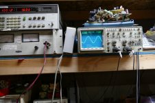
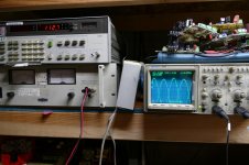
I realized that I can do it if I can just trace the curves in that area for different screen and grid voltages. I found that no existing cheap and easy curve tracing solution for that exists (etracer, for example, falls just barely short on capability). And in investigating curve tracing solutions, I found that I'd been doing "labquest" all wrong.
My current thinking is a used computer power supply (which I've picked up for a song) fed into a computer controlled DC-DC converter that I have to build. Power for the heaters, and 3 channels, one for the plate, screen, and grid, with current and voltage information for all. Set the voltages with DACs, send a synchronized pulse to all three channels at the same time, and collect the data with ADCs. Slow, but I can plot the points on a spreadsheet, and get everything I need.
Did I miss anything?
It has really helped to take some time off and to look at this after a hiatus. Things have become at least a little clearer.
First, Ik, cathode current. Somehow, I overlooked that, or perhaps I just wasn't thinking clearly. DC Ik for a KT-88 is given as 230 mA. I understand that you can exceed that by a factor of 3 "briefly", but for push-pull operation with worst-case square waves, it seems clear to me that the limit is a factor of 2.
But Ik = Ip + Is + Ig, right? (If I am in class AB2, there will be some Ig.) So, I went back to the 6L6GC datasheets (which have curves for positive grid operation), and had an epiphany. There may not be much power on the grid because there's never much voltage on it, but there sure is a fair amount of current. So, based on my earlier observation (refined by PRR, much thanks) that if you divide screen voltage by internal Mu (8 in the case of a KT-88), the effect on the plate curves from positive grid voltage and screen voltage is about the same. I hadn't realized that grid current was in the same ballpark as well.
For example, on the 6L6GC curves,
Va = 30 V
Vs = 250 V
Vg = 0 V
Is = 42.5 mA
Va = 60 V
Vs = 250 V
Vg = +16 V
Ig = 50 mA!
Now, those 50 mA have to come out of that 460 (2 x 230) mA Ik budget that I have, so, it seems that I have an optimization problem. How close to that 460 mA can I get plate amps up to, and at what voltage? It's clear that I can back off on either screen or grid voltage or both, but that bends the plate curve to the right, costing me some volts on the low end. But there's some combination of screen and grid voltage that gives me the longest load line possible, the one that puts the knee of the curve as far up and over as I can get it. I just have to find what those values are.
I realized that I can do it if I can just trace the curves in that area for different screen and grid voltages. I found that no existing cheap and easy curve tracing solution for that exists (etracer, for example, falls just barely short on capability). And in investigating curve tracing solutions, I found that I'd been doing "labquest" all wrong.
My current thinking is a used computer power supply (which I've picked up for a song) fed into a computer controlled DC-DC converter that I have to build. Power for the heaters, and 3 channels, one for the plate, screen, and grid, with current and voltage information for all. Set the voltages with DACs, send a synchronized pulse to all three channels at the same time, and collect the data with ADCs. Slow, but I can plot the points on a spreadsheet, and get everything I need.
Did I miss anything?
There simply are no ratings for grid dissipation, either for KT-88 or for 6L6GC. We tried to guess at them earlier in this thread. KT-88 screen is rated at 8.0 watts and 6L6GC screen at 5.0 watts, but we figure perhaps 1.0 watts for the grid. Maybe.
No way to tell for sure save to fire it up and see if something glows. But there are curves in the GE manual for 6L6GC for both screen and grid current as a function of plate voltage for screens up to 400 V and grid up to +20 V.
At Vs = 400 and Vg = +20, the knee of the plate curve is at about 140 V, 610 mA. Is that approved for a 6L6GC? I suspect probably not for very long, as Is under those conditions is about 60 mA.
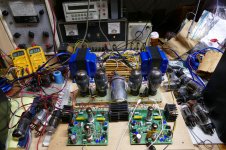
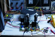
It's been over a year since I posted into this thread. During that time I have been exploring the upper limits of tube amp power working toward building that 1 KW vacuum tube HiFi amp before I get too old to move it. In this effort I have found new ways to blow stuff up.....yes I made vacuum tube EXPLODE, not once but twice.
To squeeze maximum power from a pair of tubes the plate efficiency must be improved so more of your power supply energy goes into the speaker instead of making the plate glow red. The simplest way is to use a high purveyance TV sweep (line output) tube that has a HUGE cathode with far more electron emission that could ever be needed. These can indeed pull their plates down into the 10's of volts range while passing nearly an Amp of current.
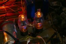
If one is convinced that common audio tubes must be used, the next best alternative is to use AB2 operating conditions. How much can AB2 help? How much power can a pair of 6L6GC's put out? Conventional wisdom says about 50 watts per pair. I was running a bunch of tubes through my test amp one day when I put a set of vintage grey glass 6L6G's from the early 1940's into the amp for a listen. These sounded good, and loud, so I measured the output power. I was surprised to read 70 watts at 1.6% THD (pictures) .
Not wanting to risk these rare tubes I stuck in some clear glass 6L6GA's from the late 40's, and leaned on them. These crusty looking tubes were probably 75 years old. I just kept turning up the knobs and the wattmeter kept climbing. I was above 100 watts from a pair when I took this picture. The next picture shows 112.7 watts at 5% THD. I decided to push things a bit farther when there was a loud bang and the fun stopped. I was at about 120 watts on 525 volts into 3300 ohms when this happened.......not bad for 75 year old 6L6GA's.
Autopsy revealed that the 1 ohm 1 watt cathode current sense resistor had exploded. That was the only failure. I replaced the resistor and turned it on to reveal the the tubes were still alive, so I cranked it up again. The results were the same, Somewhere around 120 watts the cathode resistor exploded again.
I decided to set the power supply back to 500 volts, hook up the speakers and listen to this amp for a few days. No ill effects were found in the sound, or reliability….. So what happened.
Further experiments with different tubes led me to believe that this failure mechanism is a tube arc. If you try to extract more electrons from the cathode "space charge" cloud that are available a localized arc can occur. This is not unlike secondary breakdown in a semiconductor device. If the current is limited to a low enough value (obviously over an amp in this case) the tube may lose a chunk of it's cathode coating, but otherwise survive. If enough current flows the tube WILL explode, more on this later.
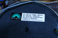
If a pair of old 6L6G's can deliver 70 watts, or even 100 watts, what can bigger tubes do? My biggest pair of TV sweep tubes can do over 250 watts and sustain that for several minutes continuously. The screen supply failed on a push to 300 watts. I will probably use 3 pair in the 500 WPC amp for safety margin.
I must go now, but I'll post more later.
To squeeze maximum power from a pair of tubes the plate efficiency must be improved so more of your power supply energy goes into the speaker instead of making the plate glow red. The simplest way is to use a high purveyance TV sweep (line output) tube that has a HUGE cathode with far more electron emission that could ever be needed. These can indeed pull their plates down into the 10's of volts range while passing nearly an Amp of current.
If one is convinced that common audio tubes must be used, the next best alternative is to use AB2 operating conditions. How much can AB2 help? How much power can a pair of 6L6GC's put out? Conventional wisdom says about 50 watts per pair. I was running a bunch of tubes through my test amp one day when I put a set of vintage grey glass 6L6G's from the early 1940's into the amp for a listen. These sounded good, and loud, so I measured the output power. I was surprised to read 70 watts at 1.6% THD (pictures) .
Not wanting to risk these rare tubes I stuck in some clear glass 6L6GA's from the late 40's, and leaned on them. These crusty looking tubes were probably 75 years old. I just kept turning up the knobs and the wattmeter kept climbing. I was above 100 watts from a pair when I took this picture. The next picture shows 112.7 watts at 5% THD. I decided to push things a bit farther when there was a loud bang and the fun stopped. I was at about 120 watts on 525 volts into 3300 ohms when this happened.......not bad for 75 year old 6L6GA's.
Autopsy revealed that the 1 ohm 1 watt cathode current sense resistor had exploded. That was the only failure. I replaced the resistor and turned it on to reveal the the tubes were still alive, so I cranked it up again. The results were the same, Somewhere around 120 watts the cathode resistor exploded again.
I decided to set the power supply back to 500 volts, hook up the speakers and listen to this amp for a few days. No ill effects were found in the sound, or reliability….. So what happened.
Further experiments with different tubes led me to believe that this failure mechanism is a tube arc. If you try to extract more electrons from the cathode "space charge" cloud that are available a localized arc can occur. This is not unlike secondary breakdown in a semiconductor device. If the current is limited to a low enough value (obviously over an amp in this case) the tube may lose a chunk of it's cathode coating, but otherwise survive. If enough current flows the tube WILL explode, more on this later.
If a pair of old 6L6G's can deliver 70 watts, or even 100 watts, what can bigger tubes do? My biggest pair of TV sweep tubes can do over 250 watts and sustain that for several minutes continuously. The screen supply failed on a push to 300 watts. I will probably use 3 pair in the 500 WPC amp for safety margin.
I must go now, but I'll post more later.
Attachments
Quit teasing us, I want to see some broken glass!
So, I am in the middle of developing a new topology I call the Compound Electron Device which is used in a new amp I call the UNSET (SET with no true triodes), and will be used in the 500 WPC monster. It allows TV sweep tube to make pretty triode curves without violating the screen grid ratings.
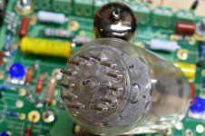
I might have two engineering degrees, but math and I don't get along too well....ditto basic arithmetic. I wire up a 6HJ5 which is a 24 watt sweep tube to a mosfet and set up the test to plot the triode curves. I set up the pulsed test to run the tubes up into the 40 to 50 watt range. I tend to do the high power tests first, but I was surprised to see scattered mosfet, cathode resistor, and a cracked tube on the initial test.
Not quite understanding what happened, I simply replaced all the dead parts and tried again. This time the tube scattered itself all over the bench and floor........OK, the dumm blonde one stops to think and realizes that 400 volts at 1 amp is not 40 watts! The big azz power supply I use for these experiments is an old style 60 Hz switcher with 1000 uF of capacitance right across it's output. The stored energy in this monster can make stuff explode and turn an OPT into a magnet.
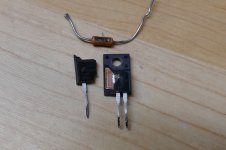
The peak current pulse that went through the plate and cathode pins cracked the glass on the first tube and scattered the mosfet in the cathode circuit. When I rebuilt, I used a bigger mosfet. The pulse blasted the glass on the second tube and made the current sense resistor disappear. Note the absence of a plate pin. It was still in the socket.
The plate of the shattered tube was peeled back to reveal a spot about 4 mm in diameter on the cathode where the coating was gone. This is where the tube arc occurred. All the tube current was concentrated in this small spot. I believe that the shattering was caused by the plate lead being blasted in half right where it passes through the glass.
The details of the CED are in post #9 here:
https://www.diyaudio.com/forums/tub...sing-mosfet-ultralinear-feed.html#post6267790
And the UNSET is here:
UNSET is coming?
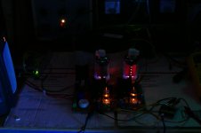
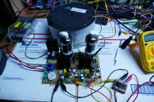
I recently took a prototype UNSET board and fed the two channels out of phase using a small Edcor transformer as a phase inverter. The balance was not perfect as can be seen in the tube color. I wired a BIG OPT across the two channels and dialed back the idle current out of class A. I then explored the upper limits of power. The picture was taken in a dark room after the board had been cranking out 250 watts for several minutes. The right tube is fed directly from the audio oscillator while the left one goes through the transformer and gets a little less drive. Attempts to get 300 watts blew the screen regulator on the UNSET board. More testing soon!
or perhaps a molten glass taking the shape of the plates....
I did that once by accident when I worked in a TV repair shop in 1969. Unfortunately the 6KD6 got real hot real quick, so I yanked the power cord. Then the tube cooled and soldered itself into the socket. I broke it trying to get it out before the boss came back.
All attempts to recreate this effect have failed. Either I get blown tubes or the tube goes gassy and glows blue, then the heat dissipation drops. I did manage to apply enough power to a blue monster to make the glass bulge outward! The technique used is the same one that I used in high school to win a bet with the teacher. I made the outer envelope on a metal 6L6 glow red....and stunk up a whole wing of the school in the process.
Attachments
- Status
- This old topic is closed. If you want to reopen this topic, contact a moderator using the "Report Post" button.
- Home
- Live Sound
- Instruments and Amps
- KT-88s: To the Pain