Hello, what would be the best combination of tubes for a guitar amp?
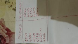
PRE
6EM7 DOUBLE TRIODE MU.68
6GK5 SINGLE TRIODE MU.78
6CG8 TRIODE PENTODE MU.40
6EA8 TRIODE PENTODE MU.40
6CG7 DOUBLE TRIODE MU.20
6AU6 PENTODE
AMP
6DQ6
6AQ5
6EM5
12BY7
6CH6
ALL TUBES ARE FROM A OLD TV
PRE
6EM7 DOUBLE TRIODE MU.68
6GK5 SINGLE TRIODE MU.78
6CG8 TRIODE PENTODE MU.40
6EA8 TRIODE PENTODE MU.40
6CG7 DOUBLE TRIODE MU.20
6AU6 PENTODE
AMP
6DQ6
6AQ5
6EM5
12BY7
6CH6
ALL TUBES ARE FROM A OLD TV
Attachments
Last edited:
What output transformer do you have? What power transformer? Tubes are the inexpensive part.
Hello! I wil use 220/6 ---> 6/220 v for the power supply and for de audio i want to use comertial voltage transformer, so the max B + for the pentode must be 200vdc
Ah, not so.Hello! I wil use 220/6 ---> 6/220 v for the power supply and for de audio i want to use comertial voltage transformer, so the max B + for the pentode must be 200vdc
Have a look at the work done by GCWills using voltage multipliers on the Lamington range of amps (over at AGGH or on the Valveheaven site)
As to "the best tube" you've not yet told us what sort of sound you want. And even then, tube choice is below circuit design & voicing and speaker choice. Read your Rob Robinette.
Thanks to everyone for the answers, in fact, what drives me to design an amplifier with these valves is that I got them from a TV that I found in the trash. I'm not a musician, I do not play any instruments, I just like electronics and I can build amplifiers for guitar and then sell them. Very simple circuits that sound relatively good. 220 / 6v faced transformers for the power source. commercial transformers for audio output. Treble cut as tone control. Master volume. maybe a gain control if double triodes are used
I would choose the two Pentode/Triode Combo tube for preamp. It should provide enough gain for Guitar amp propose. For Output tube, the 6DQ6 should give you the most power. If you use silicon rectifier, you should be able to get close to 300V DC out. Also as said in post #5, you can use voltage doubler circuit should you want to to get higher B+ still. May be too much for your purpose however.
You didn't say how many of each tube you had, so I'm assuming one of each. You don't say how much tube amp design and build experience you have either, so I'm assuming average.....
Yes, the 6DQ6 will make the most power. This is the tube that confused me so much as a rookie amp builder in the 60's......why does the little tube (6BQ6) rock and get loud, when the big one (6DQ6) just glows red and won't crank (get loud). I now know a bit more about impedance, load lines and biasing, and understand that the 6DQ6 is best used in push pull where a pair will crank out 100 watts.......
So what do you build with what you have......where did I start in 1964? With a Fender Champ 5C1. I used the 6SJ7 and sometimes a 6V6, but more often the 6BQ6, just because I got them from old TV sets (real common in the 60's).
The 6AU6 is a shrunken 6SJ7, and the 6AQ5 is a shrunken 6V6, so you should be able to start with a 5C1 schematic, use silicon diodes instead of the 5Y3, then make it work. Once working get rid of the grid leak bias on the input stage by making the grid resistor about 100K and adding a cathode resistor of about 1.5K with a cap across it. Try 10uF or 22 uF then tweak for tone. This is an easy build and works reasonably well. Then you can add a tone stack and make up for the lost gain with the 6GK5.
With due respect, what you say amounts to: "I found 3 non matching car wheels at a junkyard, what car can I build with them?"
You have, as has been told above,the cheapest set of parts , and to boot , very poorly suited for a Guitar amplifier.
Short answer: no, you can not build a Guitar amplifier with those.
You have, as has been told above,the cheapest set of parts , and to boot , very poorly suited for a Guitar amplifier.
Short answer: no, you can not build a Guitar amplifier with those.
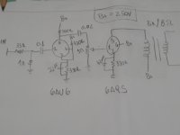
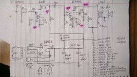
That should at least make sound with one exception. Remove the capacitor on the grid of the 6AU6 and replace it with a short. Use the same resistor - capacitor filter / decoupling scheme on the B+ line that Fender did with the 5C1. Exact values are not critical, but simply tying all the "B+" connections to the same point will lead to hum, instability and possible oscillation.
Fender Champ 5C1 Wiring Diagram | My Fender Champ | Vintage Amps
Fender Champ 5C1 Wiring Diagram | My Fender Champ | Vintage Amps
Last edited:
no, you can not build a Guitar amplifier with those.
Gibson did. I don't remember the model number but I had an old Gibson amp that used a 6AU6, a 6AQ5 and a 6X4 rectifier. Schematic was similar to the 5C1.
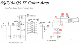
Once it's working, then add the 6GK5 and make s SE version of this....it's the only working guitar amp I have right now, and it works well enough that I haven't had the urge to build anything else....yet.
The power supply is overly complicated to allow the use of series heater string tubes. This amp was designed for absolute minimum parts cost several years ago. The tubes used are still available for $1 each, so as stated they are cheap. The power transformer is the most expensive part at $16 and the OPT is the runner up at $5.
The mosfet load on the input stage allows for a near infinite load impedance for way tooooo much gain. It can be dialed back with the pot. All this can be left out for simplification. The second mosfet is the PI, and is not needed for SE.
I'm assuming that the OP is not in the USA since he talks about 220 volt transformers, so parts availability is not always so simple, and 3 non matching wheels can be a possibility. My first car had non matching junk yard wheels.....it got me around just fine until I collected enough matching 15 inch rims and tires.
Some of what I used to make free guitar amps out of makes these tubes look like they were hand picked. I would pull a radio out of a junk car just to get those big TO-36 germanium power transistors off the back. Grabbed the OPT too.
If the TV set is still around follow the wires from the deflection yoke on the CRT. 2,3 or 4 of those wires should lead to a small transformer. IF that transformer has 4 wires, red, blue, black and green, grab it......it makes a good OPT for a small guitar amp like this.
Attachments
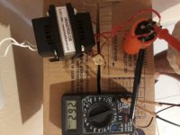
First I will mount the power source with two 22 / 6v trafos and measure the voltage, I hope to reach about 250vc.
Afterwards, I assemble the circuit and correct the necessary components.
What voltages should i have on the plate and cothode of the two valves?
for the 6aq5, according to the data sheet, it would be 200v on the plate and -12 on the cathode, is it correct?
Thank you.
Afterwards, I assemble the circuit and correct the necessary components.
What voltages should i have on the plate and cothode of the two valves?
for the 6aq5, according to the data sheet, it would be 200v on the plate and -12 on the cathode, is it correct?
Thank you.
...amounts to: "I found 3 non matching car wheels at a junkyard, what car can I build with them?" ...the cheapest set of parts , and to boot , very poorly suited for a Guitar amplifier. Short answer: no, you can not build a Guitar amplifier with those.
A TV (if working!!) has a Loudspeaker Amp.
He could have extracted the *whole* audio system (driver, 6AQ5, OT) and got audio from line level. Almost any other tube in front (or a hi-gain 6AU6 driver) will boost Guitar to line level.
I do agree that he may be missing KEY parts he could have took from the TV. Also most TV tubes were crap, and very-tired by the time they are "found in trash". The TV PT or loudspeaker would not be real suitable, and what about a cabinet or chassis? By the time he sources ALL the parts, he will have more money/time invested than he could ever sell it for, at least in a market open to low-price Asian tube amps. Could be different if Cardio had a strong reputation as an Amp Genius, but apparently he doesn't. Unless his local economy is very unique (100% tariff on imports, mountain trucking), I don't see a sale here.
First I will mount the power source with two 22 / 6v trafos and measure the voltage, I hope to reach about 250vc.
Afterwards, I assemble the circuit and correct the necessary components.
What voltages should i have on the plate and cothode of the two valves?
for the 6aq5, according to the data sheet, it would be 200v on the plate and -12 on the cathode, is it correct?
Thank you.
Try googling 6aq5 and 6v6 amps and learn something from the schematics.
Thank you! I do not have much theoretical experience but I do have some practice.
I've already done dozens of pedals and several valvular amplifiers and solid state, but always with help or following other people's projects step by step. in the end one can build an amplifier without knowing concretely how it works. What I find most difficult to understand are the curves of the valves to calculate their peripheral components.
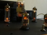
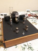
the televisions were in good condition, I was able to collect all of their valves and sockets addition to the transformers and some components.
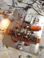
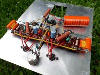
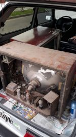
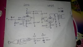
I leave you some photos of the teles and what I have done with them. a stereo amplifier with 6u8 in the pre and 6bq5 for the power.
I've already done dozens of pedals and several valvular amplifiers and solid state, but always with help or following other people's projects step by step. in the end one can build an amplifier without knowing concretely how it works. What I find most difficult to understand are the curves of the valves to calculate their peripheral components.
the televisions were in good condition, I was able to collect all of their valves and sockets addition to the transformers and some components.
I leave you some photos of the teles and what I have done with them. a stereo amplifier with 6u8 in the pre and 6bq5 for the power.
Attachments
Last edited:
https://www.ax84.com/p1/P1_Theory_Document.zip
http://mirror.thelifeofkenneth.com/...Audio_Norman_Crowhurst_1959_Volume_2_text.pdf
http://mirror.thelifeofkenneth.com/...Audio_Norman_Crowhurst_1959_Volume_3_text.pdf
http://www.tubebooks.org/Books/Atwood/Crowhurst Cooper 1956 High Fidelity Circuit Design.pdf
http://www.tubebooks.org/Books/Pullen_Conductance.pdf
- Status
- This old topic is closed. If you want to reopen this topic, contact a moderator using the "Report Post" button.
- Home
- Live Sound
- Instruments and Amps
- Best combination for a guitar tube amp!