For a long time I've been planning on building my own tube guitar amplifier resembling the classical Marshall 1974X but adding some features to adapt it to my needs.
The following features I had in mind were:
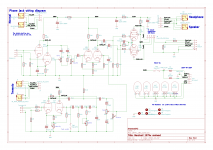
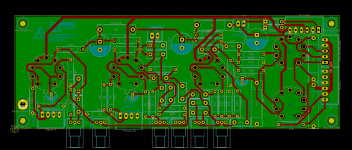
My main question right now is how to do the proper grounding of this amp. Considering that the guitar signal is unbalanced and that most of the 6.35 plugs are non-isolated from the chassis I am considering using the chassis itself as the star ground as I've seen in other post in this forum. The plugs will be connected directly to the chassis and the PCB will have a single point connection to the chassis as well. My plans is to locate the terminal close to the connectors J7 and J8 to reduce the current path of the input signal. The PCB is designed to have the most sensitive signal away from the power supply side, With the heater traces laid-out as far as possible from the signal path and with 90° angle between them and the signals when possible.
What do you think about this grounding strategy?
Do do you have any recommendations for this design?
The following features I had in mind were:
- It has to include a Headphone output
- It will use a PCB instead of point-to-point construction
- It will be a head only.
My main question right now is how to do the proper grounding of this amp. Considering that the guitar signal is unbalanced and that most of the 6.35 plugs are non-isolated from the chassis I am considering using the chassis itself as the star ground as I've seen in other post in this forum. The plugs will be connected directly to the chassis and the PCB will have a single point connection to the chassis as well. My plans is to locate the terminal close to the connectors J7 and J8 to reduce the current path of the input signal. The PCB is designed to have the most sensitive signal away from the power supply side, With the heater traces laid-out as far as possible from the signal path and with 90° angle between them and the signals when possible.
What do you think about this grounding strategy?
Do do you have any recommendations for this design?
Attachments
Your schematic has some kind of file error, please reupload it.
That said, forget earphones, there are two very important reasons for that:
1) you will burn your amp.
2) they sound HORRIBLE, specially in this amp.
Earphones belong in Hi Fi stuff and at most in SS practice amplifiers ... where they still sound BAD but at least burn nothing.
Do you know what a star ground is?
What you are doing is the exact opposite.
In any case, please build this amplifier on turrets or eyelet boards, the way God (or Jim) intended.
Maybe there is a reissue built on PCB ... be certain that if so Marshall hired very experienced PCB designers and even so, design must have gone through a few iterations until they were happy with results.
That said, forget earphones, there are two very important reasons for that:
1) you will burn your amp.
2) they sound HORRIBLE, specially in this amp.
Earphones belong in Hi Fi stuff and at most in SS practice amplifiers ... where they still sound BAD but at least burn nothing.
Are you going to cut it into long narrow strips with a Dremel wheel so each is a conductor separated from all others, joining only at supply 0?I am considering using the chassis itself as the star ground
Do you know what a star ground is?
What you are doing is the exact opposite.
In any case, please build this amplifier on turrets or eyelet boards, the way God (or Jim) intended.
Maybe there is a reissue built on PCB ... be certain that if so Marshall hired very experienced PCB designers and even so, design must have gone through a few iterations until they were happy with results.
This can be done, but it is a more complex job than it appears at first sight....It has to include a headphone output...
The problem is that a heavily overdriven guitar amp generates a lot or very harsh, very unpleasant distortion at high frequencies. A normal guitar speaker has very little response above 3 - 4 kHz, so the speaker filters out all this horrible distortion before the sound reaches your ears.
I'm attaching a couple of guitar speaker frequency responses taken from manufacturer data sheets, so you can see how drastically treble is cut off above 4 or 5 kHz.
Even cheap headphones will have a much wider, flatter frequency response - they will not filter out the harsh treble distortion, and so your amp will sound horrible through the headphones. There is also a very real risk of damaging your hearing - our ears cannot tolerate loud, high-frequency distortion.
There is a solution: you have to put some sort of guitar speaker emulation circuit (basically a specialized filter) between the output of the amplifier and the headphone socket, to remove all the harsh treble before it reaches the headphones. You can find some designs for speaker emulation filters online.
When using the headphones, you also have to provide the output valves (EL84) with a proper 8 ohm load capable of handling the full output power of the amplifier continuously. If you don't provide this load, there is a good chance of damaging your amplifier. The output transformer, output valves, and other components are at risk of being destroyed.
The load must be automatically switched into place as soon as the speaker is unplugged, so one possibility is to use a switching jack for the amp's speaker output, and wire an 8 ohm, 50 watt resistor to it to act as the dummy load when the speaker is unplugged. (The resistor will get hot, so mount it in such a way it doesn't damage anything.)
Finally, you also have to drastically reduce the amount of signal before it reaches the headphones. Your amp might be capable of spitting out ten or twelve volts RMS to the speaker at full output - you will have to reduce this to something like a few hundred millivolts before feeding it to headphones, otherwise you will immediately destroy both your hearing and your headphones. Most headphones can spit out 100 dB loudness at your ears with an input power of only one thousandth of a watt (i.e. 1 mW.)
Regarding your other question/decision, using the entire case as a ground is a very peculiar grounding strategy. However, I know of at least one guitar amp builder who does this successfully. He is an Australian gentleman named Darryl Hoy, and his hobby business is building guitar amps under the brand "Valvetone".
Valvetone amps are built into die-cast metal boxes, and photos show all interior tag strips grounded to the metal case. The circuit is then built point-to-point on the tag strips. So all grounds end up going to the metal box itself.
Mr. Hoy has many decades of experience at building valve guitar amps, and his "entire case is ground" designs seem to work well and be well-loved by his customers. Clearly, he knows how to pull off this very odd engineering approach and make it work well.
Whether a lesser mortal can pull off the same trick, I do not know. It would be an experiment, and you could certainly try it, if you don't mind the possibility that it might not work properly.
-Gnobuddy
- Status
- This old topic is closed. If you want to reopen this topic, contact a moderator using the "Report Post" button.