Hi all,
When using a bridge rectifier ( 4 diodes), do I ground the secondary HV center tap or leave it floating?
What would happen if I would ground the center tap?
Second question is about the C value in CRC psu filters.
I know it is good to keep the first C small, so I do not tax the transformers too much.
Does a big second C also tax the transformer? Or is is "isolated" by the R in between?
Don't ground it. Draw a schematic and you'll see, why.
Btw, if there's a HT secondary with CT, it is usually dedicated for two way rectifying, usually by a tube. If you connect the ends of this HT winding to a bridge retifier, your DC voltage will be twice the value that you'll most probably expect.
Best regards!
Btw, if there's a HT secondary with CT, it is usually dedicated for two way rectifying, usually by a tube. If you connect the ends of this HT winding to a bridge retifier, your DC voltage will be twice the value that you'll most probably expect.
Best regards!
Depends on whether you want a bipolar supply or not.
For a bipolar supply connect the secondary CT to the junction of the reservoir caps. Connect this junction to the junction of the smoothing caps (if you have them). Take the ground for the circuit from here.
For a single rail supply ignore the CT, unless you want a lower rail voltage to for some purpose.
It is the first C (reservoir) which sets the charging current; the second C (smoother) is usually isolated by the series element - resistance or choke. The first C should not be "small" (unless you want ripple) but neither should it be huge. My usual advice is to calculate the right value, then double it.
Thank you all very much.
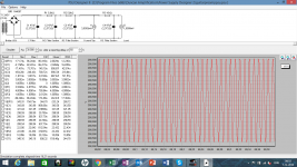
This is what I am working on below. It is for a high gain guitar preamp with two 12ax7's.
Does this looks like an ok design? Are there things I could improve?
The voltage drop of R3 is something I want to keep, the rest may be changed. The transformer is a custom ordered one, so I adjusted the voltage to account for R1 and R2.
Is the 20uV ripple at I1 low enough?
Attachments
Trobbins these are the values given by the datasheet of the F&T capacitors I will use. I did not measure the resistance of the transformer, 31 ohm is the default value. This resistance is for simulating how effective the resevoir capacitor will attack the ripple right? I have UF4007's that I will use.
DF96, is star grounding a good method for attacking psu ripple?
DF96, is star grounding a good method for attacking psu ripple?
Also be aware:
If the transformer was intended for Full Wave (CT grounded and a single diode fom each end of the secondary to a common B+ point) rather than Full Wave Bridge, then it's current rating is determined by the fact that you are drawing current from each secondary half winding on alternate half cycles of the mains ONLY.
IF you put a Bridge across the full secondary you will need to adjust the current rating to 1/2 its original rating.
As Tim says check the Cap Datasheet, I think you may have interpreted a dot as a comma. That DCR is MUCH more likely to be 2.372 Ohms than it is to be 2,372 Ohms.
Cheers,
Ian
Trobbins these are the values given by the datasheet of the F&T capacitors...
F&T makes several lines of caps, with slightly different specs. Dunno which you have.
Here is a snip from F&T Type A. Note that ESR is cited in milliOhms. 1,950 mOhm is basically 2 Ohms. The 1,300mOhm typical is in-sight of trobbin's 1 Ohm dart.
Attachments
")
No, star grounding is about the worst possible way to wire a PSU. You must use a bus ground for the PSU, even if you use a star for the rest of the audio circuit. The aim is to keep the charging pulses well away from everything else. This is repeated over and over again here and on other forums, so a little searching may help.Max999 said:DF96, is star grounding a good method for attacking psu ripple?
No, 0.7 of the original current rating.gingertube said:If the transformer was intended for Full Wave (CT grounded and a single diode fom each end of the secondary to a common B+ point) rather than Full Wave Bridge, then it's current rating is determined by the fact that you are drawing current from each secondary half winding on alternate half cycles of the mains ONLY.
IF you put a Bridge across the full secondary you will need to adjust the current rating to 1/2 its original rating.
Ok here is the funny thing about the cap esr values in psud. I have one version of psud that only lets me use comma's, and another that only lets me use dots.
Otherwise it does not even lets me enter it and states that it is "not a valid floating point value".
Possibly there is a "Euro"version ( with comma's), and a "US" version.
Otherwise it does not even lets me enter it and states that it is "not a valid floating point value".
Possibly there is a "Euro"version ( with comma's), and a "US" version.
Ok here is the funny thing about the cap esr values in psud. I have one version of psud that only lets me use comma's, and another that only lets me use dots....
Ah. I just looked at my copy (Ver: 2.1.0 build 60). I do not see any ./, option (even hidden under 50/60Hz). However as DF96 says, all likely operating systems have a Number Format preference which may be queried by applications.
That you have a copy which works "different" suggests PSUD "may" have added this ./, detection at some time in its history. (Or there could be a hangup between specific builds of PSUD and operating system quirks.)
And looking back, I don't think you would get those plots if the ESR values were off by a thousand. Sorry for suggesting it.
No issue PRR. If I would say sorry everytime I suggested something wrong to you it would be handier for me to just tattoo " sorry PRR" on my forehead.
Are there more basic steps then these for good crc psu design?:
- Set reservoir cap for a few % ripple
- Set CR for a cut-off frequency below 1 Hz
- Set transformer voltage for wanted V at goal
- Implement bus grounding
Are there more basic steps then these for good crc psu design?:
- Set reservoir cap for a few % ripple
- Set CR for a cut-off frequency below 1 Hz
- Set transformer voltage for wanted V at goal
- Implement bus grounding
- Status
- This old topic is closed. If you want to reopen this topic, contact a moderator using the "Report Post" button.
- Home
- Live Sound
- Instruments and Amps
- CT use in bridge rectifier and CRC questions