I had the same experience. I had to get the grid stoppers well above 100k in my little 6AK6 amp to get blocking distortion under control. I think I ended up with 120k.
For what it's worth, these small power pentodes and beam tetrodes only have a few picofarads of input capacitance, and 120k (or 200k in your case) should be perfectly fine with this. With 200k and, say, 10 pF of input capacitance, treble roll off only starts at 80 kHz - easily ten times more bandwidth than we need for guitar.
It's a different story with triodes, which can easily have have ten times the input capacitance. One has to watch the value of the grid stopper with those.
-Gnobuddy
Thanks for the good advice Gno, I'm going to check for some other 50L6 schematics very soon and one of them is having a 12AU6 as the preamp tube.
Still trying to find the perfect 50L6 amp for me, I'm having lots of fun with my new breadboard. For now I'm working on a design that was started from a Magnatone model 107 and with this amp I really fell in love.
As soon it's done I will post the schematic.
When the series resistor is 1/2 the to-ground resistor, grid blocking is minimized. So 100K-250K is quite reasonable for typical grid-ground resistances.
As Gno says, this rolls-off treble, and often not enough to hurt guitar, and will take the edge off of distortion from earlier stages.
hex69 suggests a resistor box, right concept, but high-gain wires run out and back tend to pick up radio and squeals. A pot on short wires may be better. I have not done this in decades.... a bag of misc resistors and a hot iron can try many values in short time.
Thanks a lot for the precision.
Well, to be honest I'm just like you, but I thought it would be a nice concept to do 'live' comparison, for example with different coupling caps.. However a good toggle switch will do.
Since I like the concept maybe I'm gonna built a smaller one with screw posts and a toggle switch, so I can swap the resistor/capacitor values on the fly, maybe that will be built directly on the breadboard with short wires, I love to experiment.
Hi people,
I'm still having fun breadboarding (all kind of) 50L6 amplifiers that I can't fix myself on which one sounds better.
The one I'm working on right now has been started from a Magnatone model 107 and I wonder what's the exact purpose of that capacitor from plate to ground?

Thank you")
I'm still having fun breadboarding (all kind of) 50L6 amplifiers that I can't fix myself on which one sounds better.
The one I'm working on right now has been started from a Magnatone model 107 and I wonder what's the exact purpose of that capacitor from plate to ground?
Thank you
The capacitor from plate to ground was pretty common in old tube radios from the 40's and 50's. It was used to roll off treble, and hence remove some of the static from the AM radio.
Many of these old guitar amps started out as a hacked radio and the cap was either inherited from the radio, or used on purpose to calm the "honk" often found when playing guitar through a cheap radio speaker from the 50's.
I have found several "dead" radios in my youth where this cap was shorted making life very short and uncomfortable for the rectifier tube and OPT. Often all the wax had melted out of the OPT and the rectifier tube was rather crispy looking, but the radio played as soon and I cut out the cap......then played better with a new 35Z5.
Feel free to experiment with a cap here, any value from nothing at all (bright) to .1 uF (pretty dark and muddy) will work, but use a 450 volt cap MINIMUM. If you plan on hitting the amp with some pedals and driving it into hard clipping, use a 600 volt cap. The plate of the 50L6 will see twice the B+ voltage in NORMAL operation, and often over 3 X B+ when overdriven into a speaker near its resonant frequency. Remember that your class A amp leaves class A as soon as you plug in the pedal board and "set the controls for the heart of the sun."
I made only one amplifier, but had several pots in it to adjust the parameters on a couple tubes. I kept messing with it over a period of several weeks and had trouble deciding on what I liked. Finally I decided to remove one pot every day or two and eventually decided on what I wanted. I put together an amp which has remained untouched for over two years......
I bought a couple of cheap Chinese guitars on Ebay that played better than my Squier Strat, so I sold the Strat to cover the cost of the new guitars, and also picked up a cheap Chinese bass.......now I feel the urge to tinker with the amp again.
I think I'm going to leave it alone and make a new one. This time I'm going to pick something I like, document it, then repeat. Once I get tired of that, I'll try to simplify it all to a minimum schematic where different parts, circuits, and even entire stages can be switched in or out with relays, fets or LDR's. Then I will get and Arduino to deal with all the switching.
I actually did something like this in the 90's with a solid state guitar amp. It used some SPI controlled chips which were managed with a PIC processor. It was a good "jack of all trades" amp, but it still had the sound of several different 90's solid state amps......I took it all apart a few years later and used the 2 X 12 combo cabinet for another one of my stupid ideas......a small tube amp that drove a 4 inch speaker inside a sealed box, which fed the same pair of LM3886 chips that were used in the multi switched amp. It sounded better, but neither design played well loud.
Many of these old guitar amps started out as a hacked radio and the cap was either inherited from the radio, or used on purpose to calm the "honk" often found when playing guitar through a cheap radio speaker from the 50's.
I have found several "dead" radios in my youth where this cap was shorted making life very short and uncomfortable for the rectifier tube and OPT. Often all the wax had melted out of the OPT and the rectifier tube was rather crispy looking, but the radio played as soon and I cut out the cap......then played better with a new 35Z5.
Feel free to experiment with a cap here, any value from nothing at all (bright) to .1 uF (pretty dark and muddy) will work, but use a 450 volt cap MINIMUM. If you plan on hitting the amp with some pedals and driving it into hard clipping, use a 600 volt cap. The plate of the 50L6 will see twice the B+ voltage in NORMAL operation, and often over 3 X B+ when overdriven into a speaker near its resonant frequency. Remember that your class A amp leaves class A as soon as you plug in the pedal board and "set the controls for the heart of the sun."
I can't fix myself on which one sounds better.
I made only one amplifier, but had several pots in it to adjust the parameters on a couple tubes. I kept messing with it over a period of several weeks and had trouble deciding on what I liked. Finally I decided to remove one pot every day or two and eventually decided on what I wanted. I put together an amp which has remained untouched for over two years......
I bought a couple of cheap Chinese guitars on Ebay that played better than my Squier Strat, so I sold the Strat to cover the cost of the new guitars, and also picked up a cheap Chinese bass.......now I feel the urge to tinker with the amp again.
I think I'm going to leave it alone and make a new one. This time I'm going to pick something I like, document it, then repeat. Once I get tired of that, I'll try to simplify it all to a minimum schematic where different parts, circuits, and even entire stages can be switched in or out with relays, fets or LDR's. Then I will get and Arduino to deal with all the switching.
I actually did something like this in the 90's with a solid state guitar amp. It used some SPI controlled chips which were managed with a PIC processor. It was a good "jack of all trades" amp, but it still had the sound of several different 90's solid state amps......I took it all apart a few years later and used the 2 X 12 combo cabinet for another one of my stupid ideas......a small tube amp that drove a 4 inch speaker inside a sealed box, which fed the same pair of LM3886 chips that were used in the multi switched amp. It sounded better, but neither design played well loud.
Hi people,
I'm still having fun breadboarding (all kind of) 50L6 amplifiers that I can't fix myself on which one sounds better.
The one I'm working on right now has been started from a Magnatone model 107 and I wonder what's the exact purpose of that capacitor from plate to ground?
Thank you

Please confirm you are using an isolation transformer with all line operated 50L6 variants or we have a problem with particular forum safety rules.
confirm you are using an isolation transformer
He posted a picture of the transformer in post #4 and it is visible in the breadboard picture in post #74.
It appears to be an industrial control transformer with a 120, 208, 230 and 460 volt primary and a 120 volt secondary. He is underfeeding the primary to get about 60 volts on the secondary to light the tubes and feed a doubler for B+.
Confirmed I am using an isolation transformer.. I posted to show that capacitor from plate to ground in the original schematic, never thought about this matter, you are correct that was my bad and I appreciate your intervention.Please confirm you are using an isolation transformer...
Here's the good schematic, not the final one but that's where I am right now, please anyone feel free to comment.
I have breadboarded lots of 50L6 amps and this one sounds different to me, I was also surprised to hear how much more power I can get by adding a bypass capacitor on the 50L6 cathode, but since I can't decide on which I like better, with or without, I thought about hooking the capacitor (C6) on a switch, is that correct?

The capacitor from plate to ground was pretty common in old tube radios from the 40's and 50's. It was used to roll off treble, and hence remove some of the static from the AM radio...
I'm used to see that capacitor hooked between the primaries of the OT, here's what I found on the web
The reason I was asking about the purpose is, when I put that capacitor in my design I'm getting some kind of a 'voltage' sound (blended with the normal guitar sound) while I hit the guitar strings, just like some electricity were blended in the sound, whatever the way I inverse the OT wires, I tried with different capacitors also, it's hard to describe maybe I should take some soundtracks of what I'm talking about.. I thought it was because of the 70V line transformer I'm using for the OT, just doesn't like that capacitor, but I tried with another (true) OT I have and got the same.The purpose of this capacitor is to absorb the energy that is stored in the core of the output transformer, in the event that the plate current driving this transformer is suddenly cut-off. The purpose of the capacitor is to "snub" excessive voltages. This plate current cut-off could happen due to static noises, or any other negative impulse at the pentode control grid. If this capacitor were absent, a sudden cutoff of current to the output plate, could easily develop over a thousand volts and this voltage could damage transformer primary insulation, or cause internal arcing in the output tube.
Feel free to experiment with a cap here, any value from nothing at all (bright) to .1 uF (pretty dark and muddy) will work, but use a 450 volt cap MINIMUM. If you plan on hitting the amp with some pedals and driving it into hard clipping, use a 600 volt cap.
That's really good to know! I was using 1000V caps there, thanks to my natural instinct!!
I made only one amplifier, but had several pots in it to adjust the parameters on a couple tubes. I kept messing with it over a period of several weeks and had trouble deciding on what I liked. Finally I decided to remove one pot every day or two and eventually decided on what I wanted. I put together an amp which has remained untouched for over two years......
I bought a couple of cheap Chinese guitars on Ebay that played better than my Squier Strat, so I sold the Strat to cover the cost of the new guitars, and also picked up a cheap Chinese bass.......now I feel the urge to tinker with the amp again.
I took it all apart a few years later and used the 2 X 12 combo cabinet for another one of my stupid ideas......a small tube amp that drove a 4 inch speaker inside a sealed box, which fed the same pair of LM3886 chips that were used in the multi switched amp. It sounded better, but neither design played well loud.
I feel like I'm reading myself! I have a couple of these chinese guitars/basses, okay they need little tweaking but I'm with you, some of them are very good and usable.I also love to experiment all kind of things, with tube amps however I'm much more careful because I have to learn a little more, most of the time I'm worried about safety concerns so those ideas are awaiting in my head for a better day!
Thank you so much again for all the good advice in my post and for sharing that long time experience you have!
He posted a picture of the transformer in post #4 and it is visible in the breadboard picture in post #74.
It appears to be an industrial control transformer with a 120, 208, 230 and 460 volt primary and a 120 volt secondary. He is underfeeding the primary to get about 60 volts on the secondary to light the tubes and feed a doubler for B+.
You are correct, actually I have 2 of them hooked in parallel, then by using the variac and depending on how I hook the secondaries, I can get whatever voltage I want from 0 to more than 800 VAC, however I'm still not sure about how much current they could take from one configuration to another so I'm not playing with those HV right now, but from the last test I did they easily live on 130ma at 300V.
I screwed them on a little board for better use:

Lately I was from a project to another, here's a tube analyser that is still in construction, just by drawing the schematic I learned a lot, not sure about all the usage it will have but one thing I'm sure about is that I want to learn a little more about tube bias. I was inspired from these diy tube matchers found online, didn't reinvent the wheel but just adapted to my taste.

Thanks
I t
Yes, you can put a switch on the cathode bypass cap. There may be a thump when the switch is flipped as the cap gets charged. You can also experiment with different resistors in series with the cap.
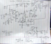
Nearly 20 years ago I made several small guitar amps loosely based on the Fender Champ. I called them Turbo Champs and no two were the same. Some used real guitar speakers and some used car stereo speakers that I got when a local K-mart store closed down. Some used the Allied power transformer shown on the schematic, some used transformers and chokes I ripped out of some old HP audio oscillators that were scrapped. Some used Hammond OPT's, and some used transformers from old TV's and radios. I did use the cap and switch arrangement on the output tube in some amps, but didn't put it in the schematic. All the switches show 3 positions, because I had a big box of 3 way switches.
I drew this schematic from memory after the fact, so it is "best guess" and probably doesn't match any one of the amps exactly. Feel free to steal any of the switch ideas I used.
I plan to recreate something like this on a bigger scale, except it will use relays and a microcontroller so it can be operated by footswitch, or even buttons on the guitar.
hought about hooking the capacitor (C6) on a switch, is that correct?
Yes, you can put a switch on the cathode bypass cap. There may be a thump when the switch is flipped as the cap gets charged. You can also experiment with different resistors in series with the cap.
Nearly 20 years ago I made several small guitar amps loosely based on the Fender Champ. I called them Turbo Champs and no two were the same. Some used real guitar speakers and some used car stereo speakers that I got when a local K-mart store closed down. Some used the Allied power transformer shown on the schematic, some used transformers and chokes I ripped out of some old HP audio oscillators that were scrapped. Some used Hammond OPT's, and some used transformers from old TV's and radios. I did use the cap and switch arrangement on the output tube in some amps, but didn't put it in the schematic. All the switches show 3 positions, because I had a big box of 3 way switches.
I drew this schematic from memory after the fact, so it is "best guess" and probably doesn't match any one of the amps exactly. Feel free to steal any of the switch ideas I used.
I plan to recreate something like this on a bigger scale, except it will use relays and a microcontroller so it can be operated by footswitch, or even buttons on the guitar.
Attachments
An attractive $100 electric guitar demonstrated by a very good guitarist: YouTube
A $200 tube (valve) guitar amp, demonstrated by the same guy: YouTube
$100 worth of upgrade parts for your $100 guitar, if you decide to go that route: YouTube
How to make your guitar play better (learn to do a set-up): YouTube
The inescapable conclusion from the first two videos is that a good guitarist, who knows what he's doing, can sound fantastic with a $100 guitar and $200 tube amp.
-Gnobuddy
I went for the $46 (with shipping) Chinacaster and I used a 15% off coupon, so I paid $39 for it. I have this one...same color, and other than a few hours to set it up have done nothing to it and it beats the Squier that I sold, which was never quite right. I will probably put some lighter gauge strings on someday.
YouTube
I got a set of the $12 pickups too, but haven't tried them yet. They are for another Squier that I have in a box somewhere in pieces. I stole it's neck for a DIY guitar experiment several years ago. No hurry to put it all back together.
YouTube
Got one of these too.....
YouTube
And a bass.....
YouTube
I sold the Carlo Robelli hollow body bass and Squire Strat for enough to cover all three new guitars and I like the new ones better. I again used an Ebay coupon for a discount. Both of those purchases were kinda spur of the moment things when the coupon was about to expire.....
The Behringer Model D was actually planned, but I held out until one of those instant coupons popped up, and bought a "B" stock unit. A MiniMoog clone for $230, couldn't say no and it ROCKS!
YouTube
I got a set of the $12 pickups too, but haven't tried them yet. They are for another Squier that I have in a box somewhere in pieces. I stole it's neck for a DIY guitar experiment several years ago. No hurry to put it all back together.
YouTube
Got one of these too.....
YouTube
And a bass.....
YouTube
I sold the Carlo Robelli hollow body bass and Squire Strat for enough to cover all three new guitars and I like the new ones better. I again used an Ebay coupon for a discount. Both of those purchases were kinda spur of the moment things when the coupon was about to expire.....
The Behringer Model D was actually planned, but I held out until one of those instant coupons popped up, and bought a "B" stock unit. A MiniMoog clone for $230, couldn't say no and it ROCKS!
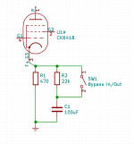
George didn't mention it, but simply putting a large resistor in parallel with the switch will get you thump-free switching. The resistor lets the cap charge up to the right DC voltage in advance, but the big resistor doesn't let it bypass the cathode until the switch is flipped.Yes, you can put a switch on the cathode bypass cap. There may be a thump when the switch is flipped as the cap gets charged.
The exact value of the resistor is not important. It needs to be much bigger than the actual cathode bias resistor (470 ohms in your schematic.) And it needs to be small enough to supply whatever small leakage current the 100uF cap needs, so don't use an enormous value such as 1 meg. I picked 22k for the schematic, but anything from 10k to 100k should work just fine.
The picture shows what I mean. (Please ignore the weird pentode model name and pin numbering - I just grabbed the first pentode symbol I found in Kicad, to stand in for your 50L6.)
-Gnobuddy
Attachments
That's what I'm gonna do.. I wonder why any commercial amplifier is having that switching option?Yes, you can put a switch on the cathode bypass cap. There may be a thump when the switch is flipped as the cap gets charged. You can also experiment with different resistors in series with the cap.
Had a look at your schematic.. will try some of them next time I jump on the breadboard!Feel free to steal any of the switch ideas I used.
Indeed, the habit doesn't make the monk! A friend of mine was playing on a little 'home stereo', we were young and poor but he was (and still is) a very good guitarist, nowaday he's working to make musical tracks for 'Cirque du Soleil'.The inescapable conclusion from the first two videos is that a good guitarist, who knows what he's doing, can sound fantastic with a $100 guitar and $200 tube amp.
I see.. I didn't experienced any thump while I tested on the breadboard but it's very good to know, I will use it anyway to stay on the safe side.but simply putting a large resistor in parallel with the switch will get you thump-free switching. The resistor lets the cap charge up to the right DC voltage in advance, but the big resistor doesn't let it bypass the cathode until the switch is flipped.
Many thanks gentlemen for the switching ideas and little drawing, picture is worth a thousand words!
I wonder why any commercial amplifier is having that switching option
Because switches are expensive.
A friend of mine was playing on a little 'home stereo'
My first "guitar amp" was a hacked Magnavox mono HiFi from the 50's. It actually sounded pretty good for the surf music that I played in the 60's, except for the lack of reverb.
Long life to the DIYers!! We save money (just like they do) without any comprimise!Because switches are expensive.
My first "guitar amp" was a hacked Magnavox mono HiFi from the 50's. It actually sounded pretty good for the surf music that I played in the 60's, except for the lack of reverb.
As my memory goes my first ever guitar amp was a Lloyd home stereo with the big 8 track on it, I can't remember the hack I did to plug the guitar into it but for the music I was (trying) to play at this time, it was in the 80s and I was looking for a distorted sound to play rock and all that I have was a broken Boss DS-1 which I had to hook in reverse in order to make it work
Good old time!About one year later I came across such a deal, it was Fender Super Reverb that a guy was using to listen the music, no cabinet only the chassis sat on the table.. I asked how much he wants for it.. He said, give me 20$ so I can get some beer and it's yours. A couple of month later I came across a Marshall JTM50 1969 (blonde face) and the girl was asking 200$, it was like new.
I don't have these amplifiers anymore today, wish I knew about their values at this time
I like that saying! I've never come across it before. It says a lot in a few words....the habit doesn't make the monk!
Now the big question is, does the monk build guitar amps?

-Gnobuddy
I like that saying! I've never come across it before. It says a lot in a few words.
Now the big question is, does the monk build guitar amps?
-Gnobuddy
I think it's a french proverb, hope I didn't say something bad by translating word for word, it was meant to say that you can't judge a book by its cover, or clothes don't make the man.
Can you picture this -> Made (deep) in the Himalayan Mountains using ancient methods to infuse all amplifiers with spiritual energies! Warning: Do not play for more than an hour, danger of levitation!
No, not at all, I understood exactly what it meant. Somehow the message seems clearer to me than other proverbs with the same message. Particularly now, when peoples lives are filled with so much shallow nonsense coming from every direction, that hardly anyone can even tell what is shallow, and what is deep, any longer.hope I didn't say something bad by translating word for word
Yes, I can totally see that...it's no worse than mpingo discs: The Magic of MpingoWarning: Do not play for more than an hour, danger of levitation!
-Gnobuddy
Yes, I can totally see that...it's no worse than mpingo discs: The Magic of Mpingo-Gnobuddy
Makes me think of walnut bracelet.. since the beginning of human society some would do (and say) anything to make money, all is relative they say but personnaly I don't believe in such concepts. If it's good for someone I'm okay however. For sure, some high quality (and expensive) gear are nice too, I think it's a matter of 'priorities'.. If I would do something professionnaly or in a serious way and I have the money.. why not! On the other hand, by comparing oranges with oranges, seems that all low quality gears holding a big brand name will be some kind of over-priced.
It's an old thread but back in the 70s, I built a guitar amp using a 12ax7 and 50L6. This was before 3 prong plugs so you had to be super careful. I over drived the hell out of the 50L6 and I cleared a room of people with it. We hear distortion as loudness - that little amp had so much distortion that its whomping 4 watts sounded like a 100 watts.
Meanwhile, downunder
Never underestimate the power of placebo
Makes me think of walnut bracelet.. If it's good for someone I'm okay however.
Never underestimate the power of placebo
- Status
- This old topic is closed. If you want to reopen this topic, contact a moderator using the "Report Post" button.
- Home
- Live Sound
- Instruments and Amps
- 50L6 guitar amp